X4Y604U1Wireless-N Dual Band Gigabit Router
NEXXT SOLUTIONS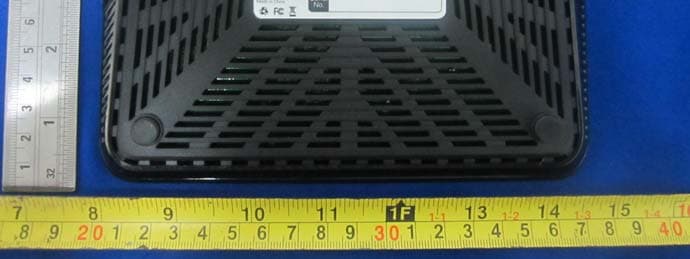
Click to zoom
Application Details
- Equipment Class
- DTS - Digital Transmission System
- Date of Grant
- Jun 03, 2013
- Application Purpose
- Original Equipment
- Date of Application
- Jun 03, 2013
- Equipment Note
- Wireless-N Dual Band Gigabit Router
- Frequency Range
- 5755.00000000 - 5795.00000000
- Company
- NEXXT SOLUTIONS
- Country
- United States
Documents & Files
Document Text
Text extracted from the exhibit documents filed with the FCC. Open a document above to read the original.
Users Manual
5GHz 5GHz 2.4GHz WAN LED indicator POWER WPS 2.4GHz On Blinking Off On Blinking Off Blinking On Off Blinking The device is powered on The system is working properly The device is powered off The 5GHz wireless connection is enabled The 2.4GHz wireless connection is enabled The 2.4 GHz connection is not in use or disabled The 5GHz connection is not in use or disabled The device is actively sending or transmitting data wirelessly over the 2.4GHz band The device is actively sending or transmitting data wirelessly over the 5GHz band The router is performing WPS authentication on a client device StatusDescription Quick Installation Guide Step 1Step 2Step 2 1 Preliminary stepsProduct layout Back Panel Side Panel Router configuration Hardware installation This advanced network device works as a router, wireless AP, switch and firewall. Before setting up the router, you must verify that you have high-speed internet access available. The most widely used connection nowadays is broadband DSL or Cable. The description used in this guide is based on that type of connection. Product layout LED indicators on the front panel provide informa- tion about network activity, the connection and link status of the ports in real time. They also facilitate activity monitoring and troubleshooting the performance of the device. The rear panel provides the physical connectors for power and the client network devices. USB 2.0 port: Multifunctional USB port supports printer sharing, file sharing and mass storage devices. Antennas: Two dual band omnidirectional antennas WAN port: This RJ45 port is where you will connect the DSL/cable modem, or Ethernet line. IPTV:This IPTV port can be used for connecting an Internet Protocol TV receiver, and as a LAN port, when the IPTV feature is not enabled. LAN ports (1-4): Connect your laptop or desktop computers in your network to any of these RJ45 Ethernet ports. WPS/Reset: Press this button for about one second to enable WPS encryption. Press this button for about seven seconds to restore the device to its factory default values. Power: Connect the supplied power adapter to this jack. 1. 2. 3. 4. 5. 6. 7. Power off your PC, cable/DSL modem and the router Find the optimum location for the router. The best place is usually at the center or your wireless network with the antennas in the upright position. Connect one end of the supplied power adapter to the AC input jack located on the rear panel of the router, before plugging the other end to a standard electrical wall outlet. Connect your network devices to the LAN ports of the router. Then using an Ethernet cable, connect your modem to the WAN port in order to gain internet access. Finally, power on the router, your PC and modem. 1. 2. 3. 4. 5. Thank you for purchasing the new Acrux 600 Dual Band Gigabit Router from Nexxt Solutions™. If any of the following items are mismatched, missing or damaged, please contact the merchant from whom you purchased the unit for immediate replacement. • ARN02604U1 Dual Band Gigabit Router • Power adapter 100-240V • Network cable • Quick installation guide Step 2Step 2Step 2 Step 2 Step 2 Step 3Step 4Step 4 Step 3 Log into the router by accessing the web base utility. To do so, in the browser’s address field enter the default address http://192.168.0.1 In this stage, the wireless router web interface will come up. The system will then prompt you to enter the default user name and password. Type admin in both cases. Click Login to continue. 1. 2. Next, the Basic Settings page will be displayed. In this window, you will be prompted to select the Access method, which will depend on the type of connection offered by your existing Internet Service Provider (ISP): ADSL, for dial-up or DHCP for other broadband connections. By default, the device is set to DHCP. Click OK to finalize the initial set up of the router. 3. 1- Two 5 dBi antennas 2 - WAN port 3 - IPTV/Gigabit LAN 4 - Three Gigabit LAN Ports 5 - WPS/Reset 6 - Power 12345786 LED indicator LAN 1-3 IPTV/LAN USB On On Blinking On Off On Off The USB port connection is enabled The USB port is not in use Off Blinking Blinking The link between the router and a device is established through that port The IPTV port connection is enabled No active connection is detected in the WAN port No active connection is detected in that LAN port The device is actively sending or transmitting Internet Protocol television signals over this port The device is actively sending or transmitting data over that port The WAN LED lights up when the wireless feature is enabled The device is actively sending or transmitting packets over that port StatusDescription 23 4 1 56 USB Storage Power Power Adapter USB Line RJ-11 TV A/V TV receiver RJ-45RJ-45 RJ-45 Phone Jack Cable/xDSL Modem 1 - Power 2 - WPS 3 - 5GHz band 4 - 2.4GHz band 5 - LAN ports 1-3 6 - IPTV/LAN port 7 - WAN port 8 - USB Quick Installation Guide Step 4Step 4 2 Step 4 To do so, right click Network > Properties > Change adapter settings, followed by Local area connections > Properties. Next, double click on Internet protocol version (4 or 6 based on your connection) and finish by selecting Obtain DNS server and IP address automatically. Please note that the path indicated above relates to Windows 7. Other operating systems may differ, so make sure to follow the instructions of the operating system you are using. If you later wish to customize your wireless router configuration, click on the Advanced Settings menu. If the computer you used to set up the router can access the internet, it means that you have success- fully configured the device, and that other computers in the LAN should also be able to do the same. If they don’t, verify that the Internet Protocol is set to obtain the IP and DNS settings automatically. 4. W Warning FCC Statement Operations in the 5.15-5.25GHz band are restricted to indoor usage only. This device complies with Part 15 of the FCC Rules. Operation is subject to the following two conditi…
Text truncated - open the document above for the full version.
Block Diagram
55 44 33 22 11 D D C C B B A A Block Diagram LAN3 PQWER/SYS 2.4G 5G RJ451X1WAN蓝色 WAN LAN2 IPTV Reset&WPSButton DC12V/2APower IN LANRJ451X3黄色 LAN1 USB IPTVRJ45 PWR 3 Inner 2 Traces 4 Bottom GND 2 Traces Top Inner 1 1 3. PCB Interface Definition 2. PCB Layer Definition 1 Block Diagram USB2.0 FR9886 Step-DownRegulator DC 5V/1ADC 3.3V/4A DC1.25V/3.5A GSS5509A Inter Regulator+ MOS +Inductance DC 2.5V Inter Regulator+ PNPB772 DC 3.3V DC 3.3V Inter POROptionReset Reset DDR232Mx16bit SPI SPIFLASH8MB20MHzXTAL 20MHzXTAL HSIC SPDT Switch Inter PA0 TX Out Inter PA0 TX Out DC 1.25V 5GHz TX0 DC 3.3V 5GHz RX1 SPDT Switch 5GHz RX0 Antenna 1Connector Diplexer Diplexer Antenna 0Connector Inter PA0 TX Out SPDT Switch 2.4GHz TX12.4GHz TX02.4GHz RX1 Inter PA1 TX Out 2.4GHz RX0 SPDT Switch 5GHz TX1 USB Interface MIC2025 USB2.0 BCM53125S DC 5V/1A DC 3.3V DC1.20V Inter Regulator+ MOS +Inductance DC 3.3V 2 1X2 Transformer WAN LAN1~4 BCM47186 RGMII DC 12V/2A FR9808 Step-DownRegulator W9751G6JBMX25L6406E BCM43236 GW2168 GW2168 AS179 AS179 DP2012 DP2012 G3601DG G1801DG 1 Transforner GSS5509A 25MHzXTAL 待定 DC 1.8V DC 3.3VDC 1.8V FS1117 LDO DC 3.3V DC 1.8V WPS DC 3.3V TitleSize Document Number Rev Date: Sheet of Block Diagram 1.0 C 418 Wednesday, April 25, 2012 TitleSize Document Number Rev Date: Sheet of Block Diagram 1.0 C 418 Wednesday, April 25, 2012 TitleSize Document Number Rev Date: Sheet of Block Diagram 1.0 C 418 Wednesday, April 25, 2012
External Photos
EXHIBIT B - EUT EXTERNAL PHOTOGRAPHS EUT –All View EUT – Top View EUT – Bottom View EUT –Left Side View EUT –Right Side View EUT – USB Port View EUT – Rear Port View EUT – Adapter View EUT – Adapter Label View
Test Report
Note: This test report is prepared for the customer shown above and for the device described herein. It may not be duplicated or used in part without prior written consent from Bay Area Compliance Laboratories Corp. This report must not be used by the customer to claim product certification, approval, or endorsement by NVLAP*, or any agency of the Federal Government. * This report may contain data that are not covered by the NVLAP accreditation and shall be marked with an asterisk “★” (Rev.2) This report is valid only with a valid digital signature. The digital signature may be available only under the Adobe software above version 7.0. FCC PART 15.247 TEST REPORT For NEXXT SOLUTIONS 3505 N.W 107TH AVE, MIAMI, FL,33178, United States Report Type: Original Report Product Type: Wireless-N Dual Band Gigabit Router Test En gineer: Ares Liu Re port Number: R2DG130515001-00A Re port Date: 2013-06-03 Reviewed By: Ivan Cao RF Leader Test Laboratory: Bay Area Compliance Laboratories Corp. (Dongguan) No.69 Pulongcun, Puxinhu Industrial Zone, Tangxia, Dongguan, Guangdong, China Tel: +86-769-86858888 Fax: +86-769-86858891 www.baclcorp.com.cn FCC ID: X4Y604U1 Bay Area Compliance Laboratories Corp. (Dongguan) Report No.: R2DG130515001-00A FCC Part 15.247 Page 2 of 132 TABLE OF CONTENTS GENERAL INFORMATION ....................................................................................................................................... 4 PRODUCT DESCRIPTION FOR EQUIPMENT UNDER TEST (EUT) ..................................................................................... 4 OBJECTIVE ................................................................................................................................................................... 4 RELATED SUBMITTAL(S)/GRANT(S) ............................................................................................................................. 4 TEST METHODOLOGY .................................................................................................................................................. 4 TEST FACILITY ............................................................................................................................................................. 5 SYSTEM TEST CONFIGURATION .......................................................................................................................... 6 DESCRIPTION OF TEST CONFIGURATION ...................................................................................................................... 6 EUT EXERCISE SOFTWARE .......................................................................................................................................... 6 EQUIPMENT MODIFICATIONS ....................................................................................................................................... 6 SUPPORT EQUIPMENT LIST AND DETAILS .................................................................................................................... 7 EXTERNAL CABLE ........................................................................................................................................................ 7 BLOCK DIAGRAM OF TEST SETUP ................................................................................................................................ 7 SUMMARY OF TEST RESULTS ............................................................................................................................... 8 FCC §15.247 (i) & §1.1310 & §2.1091- MAXIMUM PERMISSIBLE EXPOSURE (MPE) ......................................... 9 APPLICABLE STANDARD .............................................................................................................................................. 9 FCC §15.203 - ANTENNA REQUIREMENT ........................................................................................................... 10 APPLICABLE STANDARD ............................................................................................................................................ 10 ANTENNA CONNECTOR CONSTRUCTION .................................................................................................................... 10 FCC §15.207 (a) – AC LINE CONDUCTED EMISSIONS ..................................................................................... 11 APPLICABLE STANDARD ............................................................................................................................................ 11 MEASUREMENT UNCERTAINTY .................................................................................................................................. 11 EUT SETUP ................................................................................................................................................................ 11 EMI TEST RECEIVER SETUP ....................................................................................................................................... 12 TEST PROCEDURE ...................................................................................................................................................... 12 CORRECTED AMPLITUDE & MARGIN CALCULATION ................................................................................................. 12 TEST EQUIPMENT LIST AND DETAILS ......................................................................................................................... 13 TEST RESULTS SUMMARY .......................................................................................................................................... 13 TEST DATA ................................................................................................................................................................ 13 FCC §15.209, §15.205 & §15.247(d) - SPURIOUS EMISSIONS ..........................................................................…
Text truncated - open the document above for the full version.
Test Setup Photos
EXHIBIT D - TEST SETUP PHOTOGRAPHS Conducted Emission - Front View Conducted Emission - Side View Radiated Emission – Front View (Below 1 GHz ) Radiated Emission – Rear View (Below 1 GHz ) Radiated Emission – Front View (Above 1 GHz) Radiated Emission – Rear View (Above 1 GHz )
Contact Information
Applicant
Albert Mizrachi(Vice president of product development)
Test Firm
Bay Area Compliance Laboratories Corp. (Dongguan)John Chan
[email protected]86-769-86858888
Technical Specifications
| # | Rule Parts | Frequency Range | Power Output |
|---|---|---|---|
| 4 | 15C | 5.75 GHz - 5.79 GHz | 16.40 mW |
Other Applications from NEXXT SOLUTIONS
X4YHACIF25W
Aug 06, 2026Smart Camera
Equipment Class
DTS - Digital Transmission System
X4YHACOP40SL
Jul 07, 2026Smart Camera
Equipment Class
PCB - PCS Licensed Transmitter
X4YHABXL20
Jan 14, 2026Xmas string lights
Equipment Class
DTS - Digital Transmission System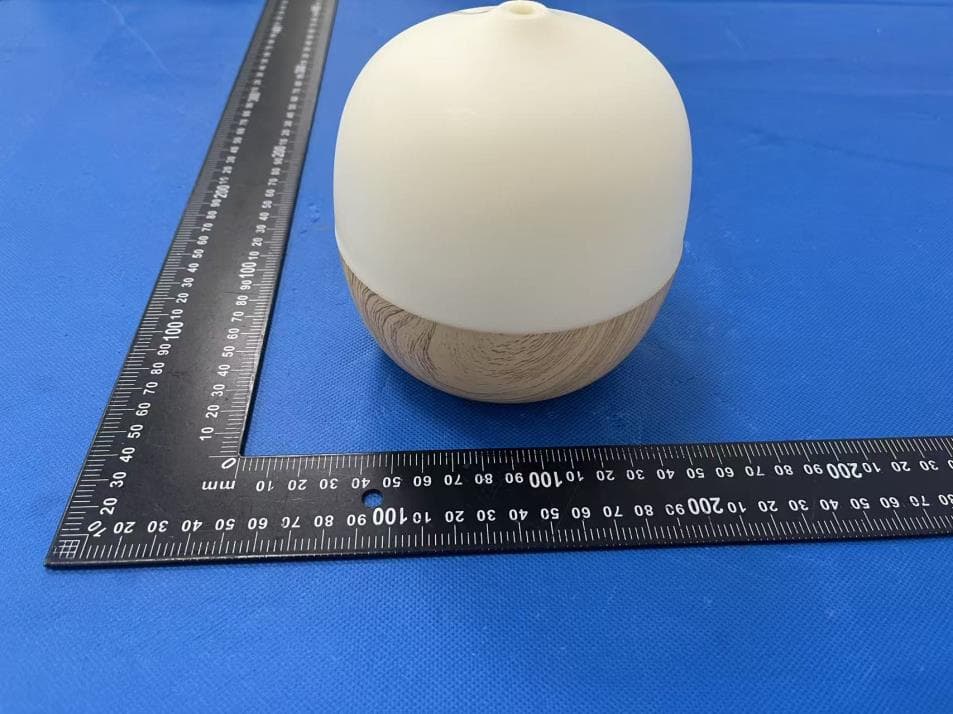
X4YHAAD300
Jan 06, 2026AROMA DIFFUSER
Equipment Class
DTS - Digital Transmission System
X4YHACIP15
Sep 28, 2025Camera
Equipment Class
DTS - Digital Transmission System