X4YLNX13ACWireless Dual-band USB Adapter
NEXXT SOLUTIONS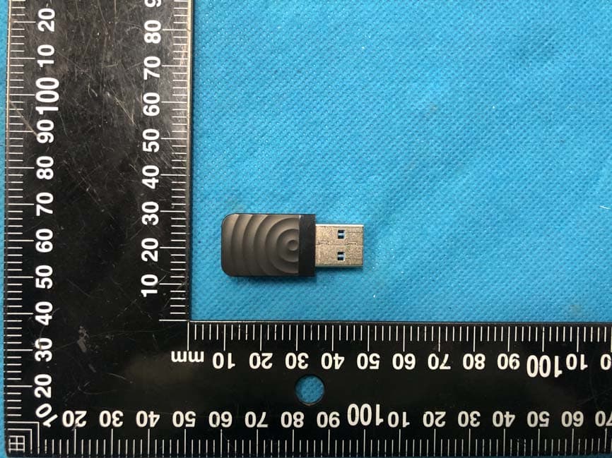
Click to zoom
Application Details
- Equipment Class
- NII - Unlicensed National Information Infrastructure TX
- Date of Grant
- May 31, 2021
- Application Purpose
- Original Equipment
- Date of Application
- May 31, 2021
- Equipment Note
- Wireless Dual-band USB Adapter
- Frequency Range
- 5745.00000000 - 5825.00000000
- Company
- NEXXT SOLUTIONS
- Country
- United States
Documents & Files
Document Text
Text extracted from the exhibit documents filed with the FCC. Open a document above to read the original.
Users Manual
5m 5m
Cover Letter(s)
FCC Software Configuration Control Declaration Rev1.0.docx NEXXT SOLUTIONS FCC Software Configuration Control Declaration Date: May. 27, 2021 Federal Communications Commission Authorization and Evaluation Division 7435 Oakland Mills Road Columbia, MD 21046 Attn: OET Dept. Product: Wireless Dual-band USB Adapter Regarding FCC Country Code Selection guidelines identified in KDB 594280 D01 v02r01 “All applications for equipment authorization for transmitters that can have radio parameters, or other technical parameters, reported to the Commission set by software must have an attestation indicating that no third party will have software, or configuration control, to program the device out of compliance of the technical rules under which it has been certified.” We declare that no third party will have software, or configuration control, to program the device out of compliance of the technical rules under which it has been certified. Date: May. 27, 2021 Name: Albert Mizrachi Title: Vice president of product development Signature of applicant Model No.: NCU-L1300
Cover Letter(s)
NEXXT SOLUTIONS Agent Authorization Company: NEXXT SOLUTIONS Address: 3505 N.W 107TH AVE. MIAMI Florida 33178, United States Product Name: Wireless Dual-band USB Adapter Model Number(s): NCU-L1300 Product Description: Wireless Dual-band USB Adapter We authorize MiCOM Labs Inc., 575 Boulder Court, Pleasanton, California 94566, USA, to act on our behalf on all matters concerning the certification of above named equipment. We declare that MiCOM Labs Inc. is allowed to forward all information related to the approval and certification of equipment to the regulatory agencies as required and to discuss any issues concerning the approval application. Any and all acts carried out by MiCOM Labs on our behalf shall have the same effect as acts of our own. Signature: Date: May. 27, 2021 Name: Albert Mizrachi Title: Vice president of product development Company: NEXXT SOLUTIONS
Cover Letter(s)
NEXXT SOLUTIONS Office of Engineering Technology Federal Communications Commission 7435 Oakland Mills Road Columbia, MD 21046 USA Date: May. 27, 2021 Subject; Request for Confidentiality FCC ID: X4YLNX13AC To Whom It May Concern, Pursuant to the provisions of the Commission’s rules Title 47 Sections §0.457 and §0.459, we are requesting the Commission to withhold the following attachment(s) as confidential documents from public disclosure indefinitely. These documents contain detailed system and equipment descriptions and are considered as proprietary information in operation of the equipment. The public disclosure of these documents might be harmful to our company and would give competitors an unfair advantage in the market. Schematic Diagram Block Diagram Parts List Operational Description Tune-up Procedure Software Security Requirement It is our understanding that all measurement test reports, FCC ID label format and correspondence during the certification review process cannot be granted as confidential documents and this information will be available for public review once the grant of equipment authorization is issued. Sincerely, Signature: Name: Albert Mizrachi Title: Vice president of product development
External Photos
Annex A External Photos Report No.:HK2105141499-1E/2E/3E Page 1 of 3 Report No.:HK2105141499-1E/2E/3E Page 2 of 3 Report No.:HK2105141499-1E/2E/3E Page 3 of 3
ID Label/Location Info
FCC ID LABEL: Ca. 5mm x 10mm Label Location FCC ID: X4YLNX13AC
Internal Photos
Annex B Internal Photo Report No.:HK2105141499-1E/2E/3E Page 1 of 2 Antenna Report No.HK2105141499-1E/2E/3E Page 2 of 2
RF Exposure Info
FCC RF Exposure EUT Description: Wireless Dual-band USB Adapter Model No.: NCU‐L1300 FCC ID : X4YLNX13AC 1. Limits According to KDB 447498 D01 General RF Exposure Guidance v06 The 1‐g and 10‐g SAR test exclusion thresholds for 100 MHz to 6 GHz at test separation distances ≤50 mm are determined by: [(max power of channel, including tune‐up tolerance, mW)/(min. test separation distance, mm)]· [√ f(GHz)]≤3.0 for 1‐g SAR and ≤ 7.5 for 10‐g extremity SAR, Where: Result=P/D*√F F= the RF channel transmit frequency in GHz P=Maximum turn‐up power in mw D=Min. test separation distance in mm 2. Test Result of RF Exposure Evaluation Output power (dBm) Tune Up Power (dBm) Max Tune Up power dBm/mW Min test separatio n distance mm Result Limit SAR Test Exclusion 2.4GWIFI 7.32 7±1 8/ 6.31 5 1.96 3.0 Pass 5.2GWIFI 6.76 6±1 7/ 5.01 5 2.28 3.0 Pass 5.8GWIFI 7.26 6.5±1 7.5/5.62 5 2.69 3.0 Pass Note: PK Output power= conducted power. Conducted power see the test report HK2105141499‐1E/2E/3E. 2.4G WIFI Gantenna gain=2dBi, 5G WIFI Gantenna gain=2dBi Per KDB 447498 D01, when the minimum test separation distance is < 5 mm, a distance of 5 mm is applied to determine RF Exposure test exclusion. The test exclusion threshold is 2.69 which is<= 3, RF Exposure testing is not required. Note: Exclusion Thresholds Results=[(max. power of channel, including tune-up tolerance, mW)/(min. test separation distance, mm)] ·[√f(GHz)] f(GHz) is the RF channel transmit frequency in GHz Distance=5mm Note: the device could not transmit simultaneously in 2.4G and 5G.
Test Report
Report No.: HK2105141499-2E FCC TEST REPORT Test report On Behalf of NEXXT SOLUTIONS For W ireless Dual-band USB Adapter Model No.: NCU-L1300 FCC ID: X4YLNX13AC Prepared for : NEXXT SOLUTIONS 3505 N.W 107TH AVE. MIAMI Florida 33178, United States Prepared By : Shenzhen HUAK Testing Technology Co., Ltd. 1-2/F., Building B2, Junfeng Zhongcheng Zhizao Innovation Park, Heping, Fuhai Street, Bao'an District, Shenzhen, Guangdong, China Date of Test: May. 17, 2021 ~ May. 24, 2021 Date of Report: May. 24, 2021 Report Number: HK2105141499-2E Page 2 of 62 Report No.: HK2105141499-2E TEST RESULT CERTIFICATION Applicant’s name .................. : NEXXT SOLUTIONS Address .................................. : 3505 N.W 107TH AVE. MIAMI Florida 33178, United States Manufacture's Name ............. : NEXXT SOLUTIONS Address .................................. : 3505 N.W 107TH AVE. MIAMI Florida 33178, United States Product description Trade Mark: NEXXT SOLUTIONS Product name ............................ : Wireless Dual-band USB Adapter Model and/or type reference . : NCU-L1300 Standards .............................. : FCC Rules and Regulations Part 15 Subpart E Section 15.407 ANSI C63.10: 2013 This publication may be reproduced in whole or in part for non-commercial purposes as long as the Shenzhen HUAK Testing Technology Co., Ltd. is acknowledged as copyright owner and source of the material. Shenzhen HUAK Testing Technology Co., Ltd. takes no responsibility for and will not assume liability for damages resulting from the reader's interpretation of the reproduced material due to its placement and context. Date of Test ............................................ : Date (s) of performance of tests ............. : May. 17, 2021 ~ May. 24, 2021 Date of Issue ........................................... : May. 24, 2021 Test Result ............................................... : Pass Prepared by: Project Engineer Reviewed by: Project Supervisor Approved by: Technical Director Page 3 of 62 Report No.: HK2105141499-2E TABLE OF CONTENTS 1. Test Result Summary ............................................................................... 5 1.1. TEST PROCEDURES AND RESULTS ............................................................................................... 5 1.2. TEST FACILITY .................................................................................................................................. 5 1.3. MEASUREMENT UNCERTAINTY ............................................................................................................... 6 2. EUT Description ........................................................................................ 7 2.1. GENERAL DESCRIPTION OF EUT ................................................................................................... 7 2.2. OPERATION FREQUENCY EACH OF CHANNEL ........................................................................................... 8 2.3. OPERATION OF EUT DURING TESTING .................................................................................................... 8 2.4. DESCRIPTION OF TEST SETUP ....................................................................................................... 9 3. Genera Information ................................................................................. 10 3.1. TEST ENVIRONMENT AND MODE ............................................................................................................ 10 3.2. DESCRIPTION OF SUPPORT UNITS ........................................................................................................ 11 4. Test Results and Measurement Data .................................................... 12 4.1. CONDUCTED EMISSION ........................................................................................................................ 12 4.2. MAXIMUM CONDUCTED OUTPUT POWER .............................................................................................. 16 4.3. 6DB EMISSION BANDWIDTH ................................................................................................................. 19 4.4. 26DB BANDWIDTH AND 99% OCCUPIED BANDWIDTH ............................................................................ 20 4.5. POWER SPECTRAL DENSITY ................................................................................................................ 27 4.6. BAND EDGE ......................................................................................................................................... 34 4.7. SPURIOUS EMISSION ........................................................................................................................... 49 4.8. FREQUENCY STABILITY MEASUREMENT ................................................................................................ 56 4.9. ANTENNA REQUIREMENT ............................................................................................................. 59 4.10. PHOTOGRAPHS OF TEST SETUP ........................................................................................................... 60 5. PHOTOS OF THE EUT ............................................................................ 62 Page 4 of 62 Report No.: HK2105141499-2E ** Modifited History ** Revision Description Issued Data Remark Revision 1.0 Initial Test Report Release May. 24, 2021 Jason Zhou Page 5 of 62 Report No.: HK2105141499-2E 1. Test Result Summary 1.1. TEST PROCEDURES AND RESULTS Requirement CFR 47 Section Result Antenna requirement §15.203 PASS AC Power Line Conducted Emission §15.207 PASS Maximum Conducted Output Power §15.407(a) PASS 6dB Emission Bandwidth §15.407(e) N/A 26dB Emission Bandwidth& 99% Occupied Bandwidth §15.407(a) PASS Power Spectral Density §15.407(a) PASS Band edge §15.407(b)/15.209/15.205 PASS Radiated Emission §15.407(b)/15.209/15.205 PASS Frequency Stability §15.407(g) PASS Note: 1. PASS: Test item meets the requirement. 2. Fail: Test …
Text truncated - open the document above for the full version.
Test Report
Report No.: HK2105141499-3E FCC TEST REPORT Test report On Behalf of NEXXT SOLUTIONS For Wireless Dual-band USB Adapter Model No.: NCU-L1300 FCC ID: X4YLNX13AC Prepared for : NEXXT SOLUTIONS 3505 N.W 107TH AVE. MIAMI Florida 33178, United States Prepared By : Shenzhen HUAK Testing Technology Co., Ltd. 1-2/F., Building B2, Junfeng Zhongcheng Zhizao Innovation Park, Heping, Fuhai Street, Bao'an District, Shenzhen, Guangdong, China Date of Test: May. 17, 2021 ~ May. 31, 2021 Date of Report: May. 31, 2021 Report Number: HK2105141499-3E Page 2 of 60 Report No.: HK2105141499-3E TEST RESULT CERTIFICATION Applicant’s name .................. : NEXXT SOLUTIONS Address .................................. : 3505 N.W 107TH AVE. MIAMI Florida 33178, United States Manufacture's Name ............. : NEXXT SOLUTIONS Address .................................. : 3505 N.W 107TH AVE. MIAMI Florida 33178, United States Product description Trade Mark: NEXXT SOLUTIONS Product name ............................ : Wireless Dual-band USB Adapter Model and/or type reference . : NCU-L1300 Standards .............................. : FCC Rules and Regulations Part 15 Subpart E Section 15.407 ANSI C63.10: 2013 This publication may be reproduced in whole or in part for non-commercial purposes as long as the Shenzhen HUAK Testing Technology Co., Ltd. is acknowledged as copyright owner and source of the material. Shenzhen HUAK Testing Technology Co., Ltd. takes no responsibility for and will not assume liability for damages resulting from the reader's interpretation of the reproduced material due to its placement and context. Date of Test ............................................ : Date (s) of performance of tests ............. : May. 17, 2021 ~ May. 31, 2021 Date of Issue ........................................... : May. 31, 2021 Test Result ............................................... : Pass Testing Engineer : (Gary Qian) Technical Manager : (Eden Hu) Authorized Signatory : (Jason Zhou) Page 3 of 60 Report No.: HK2105141499-3E TABLE OF CONTENTS 1. Test Result Summary ............................................................................... 5 1.1. TEST PROCEDURES AND RESULTS ............................................................................................... 5 1.2. TEST FACILITY .................................................................................................................................. 5 1.3. MEASUREMENT UNCERTAINTY ............................................................................................................... 6 2. EUT Description ........................................................................................ 7 2.1. GENERAL DESCRIPTION OF EUT ................................................................................................... 7 2.2. OPERATION FREQUENCY EACH OF CHANNEL ........................................................................................... 8 2.3. OPERATION OF EUT DURING TESTING .................................................................................................... 8 2.4. DESCRIPTION OF TEST SETUP ....................................................................................................... 9 3. Genera Information ................................................................................. 10 3.1. TEST ENVIRONMENT AND MODE ............................................................................................................ 10 3.2. DESCRIPTION OF SUPPORT UNITS ........................................................................................................ 11 4. Test Results and Measurement Data .................................................... 12 4.1. CONDUCTED EMISSION ........................................................................................................................ 12 4.2. MAXIMUM CONDUCTED OUTPUT POWER .............................................................................................. 16 4.3. 6DB EMISSION BANDWIDTH ................................................................................................................. 18 4.4. 26DB BANDWIDTH AND 99% OCCUPIED BANDWIDTH ............................................................................ 25 4.5. POWER SPECTRAL DENSITY ................................................................................................................ 26 4.6. BAND EDGE ......................................................................................................................................... 33 4.7. SPURIOUS EMISSION ........................................................................................................................... 48 4.8. FREQUENCY STABILITY MEASUREMENT ................................................................................................ 55 4.9. ANTENNA REQUIREMENT ............................................................................................................. 57 4.10. PHOTOGRAPHS OF TEST SETUP ........................................................................................................... 58 5. PHOTOS OF THE EUT ............................................................................ 60 Page 4 of 60 Report No.: HK2105141499-3E ** Modified History ** Revision Description Issued Data Remark Revision 1.0 Initial Test Report Release May. 31, 2021 Jason Zhou Page 5 of 60 Report No.: HK2105141499-3E 1. Test Result Summary 1.1. TEST PROCEDURES AND RESULTS Requirement CFR 47 Section Result Antenna requirement §15.203 PASS AC Power Line Conducted Emission §15.207 PASS Maximum Conducted Output Power §15.407(a) PASS 6dB Emission Bandwidth §15.407(e) PASS 26dB Emission Bandwidth& 99% Occupied Bandwidth §15.407(a) N/A Power Spectral Density §15.407(a) PASS Band edge §15.407(b)/15.209/15.205 PASS Radiated Emission §15.407(b)/15.209/15.205 PASS Frequency Stability §15.407(g) PASS Note: 1. PASS: Test item meets the requirement. 2. Fail: Test…
Text truncated - open the document above for the full version.
Test Setup Photos
Test Model:NCU-L1300 Radiated Emission Conducted Emission
Contact Information
Applicant
Albert Mizrachi(Vice president of product development)
Technical Contact
Test Firm
Shenzhen HUAK Testing Technology Co., Ltd.Jason Zhou
[email protected]+86-755-23029901
Technical Specifications
| # | Rule Parts | Frequency Range | Power Output |
|---|---|---|---|
| 2 | 15E | 5.75 GHz - 5.83 GHz | 5.32 mW |
Other Applications from NEXXT SOLUTIONS
X4YHACIF25W
Aug 06, 2026Smart Camera
Equipment Class
DTS - Digital Transmission System
X4YHACOP40SL
Jul 07, 2026Smart Camera
Equipment Class
PCB - PCS Licensed Transmitter
X4YHABXL20
Jan 14, 2026Xmas string lights
Equipment Class
DTS - Digital Transmission System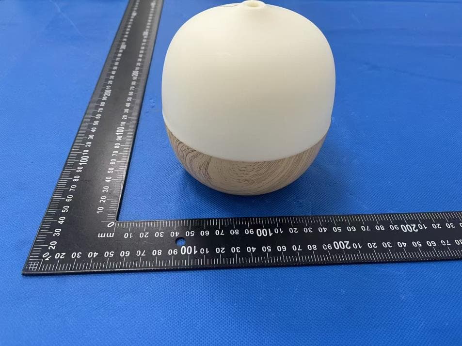
X4YHAAD300
Jan 06, 2026AROMA DIFFUSER
Equipment Class
DTS - Digital Transmission System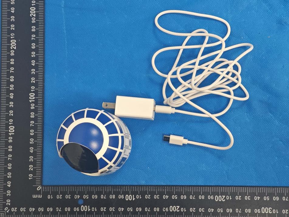
X4YHACIP15
Sep 28, 2025Camera
Equipment Class
DTS - Digital Transmission System