X4YNBL12PACDual-Band AC1200 Wireless Router
NEXXT SOLUTIONS
Click to zoom
Application Details
- Equipment Class
- DTS - Digital Transmission System
- Date of Grant
- Apr 29, 2021
- Application Purpose
- Original Equipment
- Date of Application
- Apr 29, 2021
- Equipment Note
- Dual-Band AC1200 Wireless Router
- Frequency Range
- 2412.00000000 - 2462.00000000
- Company
- NEXXT SOLUTIONS
- Country
- United States
Documents & Files
Document Text
Text extracted from the exhibit documents filed with the FCC. Open a document above to read the original.
Users Manual
WARRANTY Must register at: nexxtsolutions.com/warranty YEAR * * SPEEDS 1200 Mbps WIRELESS COMBINED ULTIMATE RANGE Model: NCR-N1200/NCR-N1200-A Nebula1200 DUAL-BAND AC WIRELESS ROUTER plus Rear panel Front panel 1. Preliminary steps 2. Product layout Thank you for purchasing the new Nebula 1200 + dual band router from Nexxt Solutions ® . If any of the following items are mismatched, missing or damaged, please contact the store from whom you purchased the unit for immediate replacement. This advanced network device works as wireless router, universal repeater and WISP client. Before setting up the router, you must verify that you have high-speed internet access available. The most widely used connection nowadays is broadband DSL, cable and AP modes. The description used in this guide is based on that type of connection. LED indicators on the front panel provide information about network activity, the connection and link status of the ports in real time. They also facilitate activity monitoring and troubleshooting the performance of the device. • Dual band gigabit wireless router • Power adapter 110/220V • Network cable • User guide LED indicator 1. SYS 3. LAN 2. WAN 4. Wi-Fi DescriptionStatus English USER GUIDE SYSWANLANWi-Fi The router is starting up or it fails to function correctly after being initialized The system is working properly The system is not working properly or it has not been powered on correctly The WAN port is connected properly but no data is being transmitted The device is actively sending or transmitting packets over that port The WAN port is either disconnected or improperly connected Port 1, 2 or 3 is connected properly A new client device has been added to port 1, 2 or 3 No wired device is connected to any LAN port of the router or the wired device is not connected properly At least the 2.4GHz or 5GHz WiFi network is enabled The device is actively sending or transmitting data wirelessly The router is performing WPS negotiation on a client device The wireless function is disabled Solid Blinking Off Solid Blinking fast Off Solid Blinking twice Off Solid Blinking fast Blinking slowly Off WPS/RSTWANPOWERLAN (IPTV/3)LAN (2,1) 54321 6 1234 Power DC-IN: Connect the supplied power adapter to this jack.. WAN port: This RJ45 port is where you will connect the DSL/ca- ble modem or ethernet line from your ISP. LAN port 1/2: Connect your local laptop or desktop computers in your network to any of these RJ45 ethernet ports. IPTV/LAN port 3: This is a LAN port by default. When the IPTV feature on the router is enabled, this port can be used for connec- ting an Internet Protocol receiver to stream videos on your TV set via a set-top box. WPS/RST button: Press and hold this button for about 8 seconds until all LEDs light up once, and then release it to restore the device to its factory default values. Press and hold for a second to use the WPS feature (if enabled). To successfully establish a WPS link, within the first 2 minutes the wireless client’s WPS feature must be enabled. Antennas: It is equipped with four dual-band omnidirectional antennas. First determine the optimum location for the router. The best place is usually at the center of your wireless network with the antennas in the upright position. Then, connect the modem to the internet port of the router using the supplied ethernet cable. Connect your PC to the router if using a wired connection. Insert one end of the supplied power adapter to the AC input jack located on the rear panel of the router, before plugging the other end to a standard electrical wall outlet. 3. Hardware installation Open a web browser to access the main web interface. Type http://www.nexxtwifi.local or 192.168.0.1 in the address bar and press Enter on the keyboard. The Quick setup wizard will come up to assist you in completing the internet settings. Click on Start to initiate the process. 4. Router configuration 1. 2. 3. 4. 5. 6. 1. 2. 3. 4. 1. 2. Select your connection type and click on Next. For the purposes of this guide, the DHCP option was selected. 3. In this screen, you can set up the Transmit power, SSID and Password. Once you finished configuring these settings, click on Next to continue. 4. 1 4 2 3 To connect to the router wirelessly, click on the wireless icon on your taskbar. 5. Connecting to Wi-Fi using Windows 10 1. Proceed to select the Wireless network followed by Connect. By default, the wireless SSID is Nexxt_XXXXXX (whereby “x“ represents the last digits of the MAC address). 2. Once done, the message stating that the setup is complete will be displayed. To configure additional settings, the user can click on the Advanced option, as illustrated below. 5. The next time you access the web interface through http://www.nexxtwifi.local or 192.168.0.1, the default Login screen will be displayed. The default user name and password is admin. 6. Enter the user defined or preassigned password, if any, and click on Next to continue. 3. If connection is successfully established, the Connected message will come up on the screen. 4. Search and install the Nexxt Wi-Fi app from the Apple or Google app store. 6. How to setup and use the Nexxt Wi-Fi app for the AC wireless router 1. For this guide, we will be using a phone based on an Android platform. Open the Nexxt Wi-Fi app. 2. 3. In order to access your router from a remote location you will have to register an account. Click on the option on the right hand corner (person icon). 4. Click on Login.5. Then click on Register.6. Enter the email address you wish to register, and assign a password. Type in the verification code displayed, and click on Register. 7.You will now need to log into the Nebula 1200 + web user interface from a PC. Once logged in, go to Advanced Settings and look for the Nexxt App. 10. Click on the Nexxt App option to enable the feature. Now type in the email address you used on the app in the Account field. Click on Save when done. 11. 12. A verification email from cloud@…
Text truncated - open the document above for the full version.
External Photos
Report No.: 2103C091 Page 1 of 10 ATTACHMENT PHOTOGRAPHS OF EUT Report No.: 2103C091 Page 2 of 10 2.4G Ant. 1 2.4G Ant. 2 5G Ant. 2 5G Ant. 1 Report No.: 2103C091 Page 3 of 10 Report No.: 2103C091 Page 4 of 10 Report No.: 2103C091 Page 5 of 10
Internal Photos
Report No.: 2103C091 Page 6 of 10 Report No.: 2103C091 Page 7 of 10 Report No.: 2103C091 Page 8 of 10 Report No.: 2103C091 Page 9 of 10 Report No.: 2103C091 Page 10 of 10
RF Exposure Info
Report No.: BTL-FCCP-3-2103C091 Page 1 of 5 FCC RF EXPOSURE REPORT FCC ID: X4YNBL12PAC Project No. : 2103C091 Equipment : Dual-Band AC1200 Wireless Router Brand Name : NEXXT Test Model : NCR-N1200 Series Model : N/A Applicant : NEXXT SOLUTIONS Address : 3505 N.W 107TH AVE. MIAMI, FL 33178 Manufacturer : NEXXT SOLUTIONS Address : 3505 N.W 107TH AVE. MIAMI, FL 33178 Date of Receipt : Mar. 09, 2021 Date of Test : Mar. 10, 2021 ~ Apr. 16, 2021 Issued Date : Apr. 27, 2021 Report Version : R00 Test Sample : Engineering Sample No.: DG2021030896 Standard(s) : FCC Guidelines for Human Exposure IEEE C95.1 & FCC Part 2.1091 FCC Title 47 Part 2.1091, OET Bulletin 65 Supplement C The above equipment has been tested and found compliance with the requirement of the relative standards by BTL Inc. Prepared by : Chella Zheng Approved by : Ethan Ma Add: No.3, Jinshagang 1st Road, Shixia, Dalang Town,Dongguan, Guangdong, China. Te l : +86-769-8318-3000 Web: www.newbtl.com Report No.: BTL-FCCP-3-2103C091 Page 2 of 5 REPORT ISSUED HISTORY Report Version Description Issued Date R00 Original Issue Apr. 27, 2021 Report No.: BTL-FCCP-3-2103C091 Page 3 of 5 1. TEST FACILITY The test facilities used to collect the test data in this report is at the location of No.3,Jinshagang 1st Road, Shixia, Dalang Town, Dongguan, Guangdong, China. BTL's Test Firm Registration Number for FCC: 357015 BTL's Designation Number for FCC: CN1240 2. MPE CALCULATION METHOD Calculation Method of RF Safety Distance: where: S = power density P = power input to the antenna G = power gain of the antenna in the direction of interest relative to an isotropic radiator R = distance to the center of radiation of the antenna Table for Filed Antenna: For 2.4GHz: Ant. Brand Model Name Antenna Type Connector Gain (dBi) 1 Tenda N/A Dipole N/A 5.09 2 Tenda N/A Dipole N/A 5.09 Note: 1) This EUT supports CDD, and all antennas have the same gain, Directional gain = G ANT +Array Gain. For power measurements, Array Gain=0dB (N ANT ≤4), so the Directional gain=5.09. For power spectral density measurements, N ANT =2, N SS = 1. So the Directional gain=G ANT +Array Gain=G ANT +10log(N ANT / N SS )dBi=5.09+10log(2/1)dBi=8.10. 2) The antenna gain is provided by the manufacturer. Table for Antenna Configuration: Operating Mode TX Mode 1TX 2TX IEEE 802.11b V (Ant. 1) - IEEE 802.11g V (Ant. 1) - IEEE 802.11n(HT20) - V(Ant. 1 + Ant. 2) IEEE 802.11n(HT40) - V(Ant. 1 + Ant. 2) Report No.: BTL-FCCP-3-2103C091 Page 4 of 5 For 5GHz: Ant. Brand Model Name Antenna Type Connector Gain (dBi) 1 Tenda N/A Dipole N/A 5.90 2 Tenda N/A Dipole N/A 5.90 Note: 1) This EUT supports CDD, and all antennas have the same gain, Directional gain = G ANT +Array Gain. For power measurements, Array Gain=0dB (N ANT ≤4), so the Directional gain=5.90. For power spectral density measurements, N ANT =2, N SS = 1. So the Directional gain=G ANT +Array Gain=G ANT +10log(N ANT / N SS )dBi=5.90+10log(2/1)dBi=8.91. 2) The antenna gain is provided by the manufacturer. Table for Antenna Configuration: Operating Mode TX Mode 1TX 2TX IEEE 802.11a V (Ant. 1) - IEEE 802.11n(HT20) - V(Ant. 1 + Ant. 2) IEEE 802.11n(HT40) - V(Ant. 1 + Ant. 2) IEEE 802.11ac(VHT20) - V(Ant. 1 + Ant. 2) IEEE 802.11ac(VHT40) - V(Ant. 1 + Ant. 2) IEEE 802.11ac(VHT80) - V(Ant. 1 + Ant. 2) Report No.: BTL-FCCP-3-2103C091 Page 5 of 5 3. TEST RESULTS For 2.4GHz: Directional Gain (dBi) Directional Gain (numeric) Max. Average Output Power (dBm) Max. Average Output Power (mW) Power Density (S) (mW/cm 2 ) Limit of Power Density (S) (mW/cm 2 ) Test Result 8.10 6.4565 24.86 306.1963 0.39351 1 Complies For 5GHz: Antenna Gain (dBi) Antenna Gain (numeric) Max. Output Power (dBm) Max. Output Power (mW) Power Density (S) (mW/cm 2 ) Limit of Power Density (S) (mW/cm 2 ) Test Result 8.91 7.7804 20.50 112.2018 0.17376 1 Complies For the max simultaneous transmission MPE: Power Density (S) (mW/cm 2 ) Power Density (S) (mW/cm 2 ) Total Limit of Power Density (S) (mW/cm 2 ) Test Result 2.4GHz 5GHz 0.39351 0.17376 0.56727 1 Complies Note: The calculated distance is 20 cm. End of Test Report
Test Report
Report No.: BTL-FCCP-1-2103C091 Page 1 of 120 FCC Radio Test Report FCC ID: X4YNBL12PAC This report concerns: Original Grant Project No. : 2103C091 Equipment : Dual-Band AC1200 Wireless Router Brand Name : NEXXT Test Model : NCR-N1200 Series Model : N/A Applicant : NEXXT SOLUTIONS Address : 3505 N.W 107TH AVE. MIAMI, FL 33178 Manufacturer : NEXXT SOLUTIONS Address : 3505 N.W 107TH AVE. MIAMI, FL 33178 Date of Receipt : Mar. 09, 2021 Date of Test : Mar. 10, 2021 ~ Apr. 16, 2021 Issued Date : Apr. 27, 2021 Report Version : R00 Test Sample : Engineering Sample No.: DG2021030896 Standard(s) : FCC CFR Title 47, Part 15, Subpart C FCC KDB 558074 D01 15.247 Meas Guidance v05r02 FCC KDB 662911 D01 Multiple Transmitter Output v02r01 ANSI C63.10-2013 The above equipment has been tested and found compliance with the requirement of the relative standards by BTL Inc. Prepared by : Chella Zheng Approved by : Ethan Ma Add: No.3, Jinshagang 1st Road, Shixia, Dalang Town,Dongguan, Guangdong, China. Te l : +86-769-8318-3000 Web: www.newbtl.com Report No.: BTL-FCCP-1-2103C091 Page 2 of 120 Declaration BTL represents to the client that testing is done in accordance with standard procedures as applicable and that test instruments used has been calibrated with standards traceable to international standard(s) and/or national standard(s). BTL's reports apply only to the specific samples tested under conditions. It is manufacture’s responsibility to ensure that additional production units of this model are manufactured with the identical electrical and mechanical components. BTL shall have no liability for any declarations, inferences or generalizations drawn by the client or others from BTL issued reports. The report must not be used by the client to claim product certification, approval, or endorsement by NVLAP, NIST, A2LA, or any agency of the U.S. Government. This report is the confidential property of the client. As a mutual protection to the clients, the public and ourselves, the test report shall not be reproduced, except in full, without our written approval. BTL’s laboratory quality assurance procedures are in compliance with the ISO/IEC 17025 requirements, and accredited by the conformity assessment authorities listed in this test report. BTL is not responsible for the sampling stage, so the results only apply to the sample as received. The information, data and test plan are provided by manufacturer which may affect the validity of results, so it is manufacturer’s responsibility to ensure that the apparatus meets the essential requirements of applied standards and in all the possible configurations as representative of its intended use. Limitation For the use of the authority's logo is limited unless the Test Standard(s)/Scope(s)/Item(s) mentioned in this test report is (are) included in the conformity assessment authorities acceptance respective. Please note that the measurement uncertainty is provided for informational purpose only and are not use in determining the Pass/Fail results. Report No.: BTL-FCCP-1-2103C091 Page 3 of 120 Table of Contents Page REPORT ISSUED HISTORY 6 1 . SUMMARY OF TEST RESULTS 7 1.1 TEST FACILITY 8 1.2 MEASUREMENT UNCERTAINTY 8 1.3 TEST ENVIRONMENT CONDITIONS 9 2 . GENERAL INFORMATION 10 2.1 GENERAL DESCRIPTION OF EUT 10 2.2 DESCRIPTION OF TEST MODES 12 2.3 PARAMETERS OF TEST SOFTWARE 13 2.4 DUTY CYCLE 14 2.5 BLOCK DIAGRAM SHOWING THE CONFIGURATION OF SYSTEM TESTED 16 2.6 SUPPORT UNITS 16 3 . AC POWER LINE CONDUCTED EMISSIONS 17 3.1 LIMIT 17 3.2 TEST PROCEDURE 17 3.3 DEVIATION FROM TEST STANDARD 17 3.4 TEST SETUP 18 3.5 EUT OPERATION CONDITIONS 18 3.6 TEST RESULTS 18 4 . RADIATED EMISSIONS 19 4.1 LIMIT 19 4.2 TEST PROCEDURE 20 4.3 DEVIATION FROM TEST STANDARD 21 4.4 TEST SETUP 21 4.5 EUT OPERATION CONDITIONS 22 4.6 TEST RESULTS - 9 KHZ TO 30 MHZ 22 4.7 TEST RESULTS - 30 MHZ TO 1000 MHZ 22 4.8 TEST RESULTS - ABOVE 1000 MHZ 22 5 . BANDWIDTH 23 5.1 LIMIT 23 5.2 TEST PROCEDURE 23 5.3 DEVIATION FROM STANDARD 23 5.4 TEST SETUP 23 Report No.: BTL-FCCP-1-2103C091 Page 4 of 120 Table of Contents Page 5.5 EUT OPERATION CONDITIONS 23 5.6 TEST RESULTS 23 6 . MAXIMUM OUTPUT POWER 24 6.1 LIMIT 24 6.2 TEST PROCEDURE 24 6.3 DEVIATION FROM STANDARD 24 6.4 TEST SETUP 24 6.5 EUT OPERATION CONDITIONS 24 6.6 TEST RESULTS 24 7 . CONDUCTED SPURIOUS EMISSIONS 25 7.1 LIMIT 25 7.2 TEST PROCEDURE 25 7.3 DEVIATION FROM STANDARD 25 7.4 TEST SETUP 25 7.5 EUT OPERATION CONDITIONS 25 7.6 TEST RESULTS 25 8 . POWER SPECTRAL DENSITY 26 8.1 LIMIT 26 8.2 TEST PROCEDURE 26 8.3 DEVIATION FROM STANDARD 26 8.4 TEST SETUP 26 8.5 EUT OPERATION CONDITIONS 26 8.6 TEST RESULTS 26 9 . MEASUREMENT INSTRUMENTS LIST 27 10 . EUT TEST PHOTO 29 APPENDIX A - AC POWER LINE CONDUCTED EMISSIONS 34 APPENDIX B - RADIATED EMISSION - 9 KHZ TO 30 MHZ 39 APPENDIX C - RADIATED EMISSION - 30 MHZ TO 1000 MHZ 44 APPENDIX D - RADIATED EMISSION- ABOVE 1000 MHZ 47 APPENDIX E - BANDWIDTH 98 APPENDIX F - MAXIMUM OUTPUT POWER 103 APPENDIX G - CONDUCTED SPURIOUS EMISSIONS 110 Report No.: BTL-FCCP-1-2103C091 Page 5 of 120 Table of Contents Page APPENDIX H - POWER SPECTRAL DENSITY 117 Report No.: BTL-FCCP-1-2103C091 Page 6 of 120 REPORT ISSUED HISTORY Report Version Description Issued Date R00 Original Issue. Apr. 27, 2021 Report No.: BTL-FCCP-1-2103C091 Page 7 of 120 1. SUMMARY OF TEST RESULTS Te s t procedures according to the technical standard(s): FCC CFR Title 47, Part 15, Subpart C Standard(s) Section Test Item Test Result Judgment Remark 15.207 AC Power Line Conducted Emissions APPENDIX A PASS ------ 15.247(d) 15.205(a) 15.209(a) Radiated Emissions APPENDIX B APPENDIX C APPENDIX D PASS ------ 15.247(a)(2) Bandwidth APPENDIX E PASS ------ 15.247(b)(3) Maximum Output Power APPENDIX F PASS ------ 15.247(d) Conducted Spurious Emissions APPENDIX G PASS ------ 15.247(e) Power Spectral Density APPENDIX H PASS ------ 15.203 Antenna Requirement ------ PASS Note(2) Note: (1) “N/A” denotes test is not applicable in this test report. (2) The device wha…
Text truncated - open the document above for the full version.
Test Report
Report No.: BTL-FCCP-1-2103C091 Page 113 of 120 Test Mode TX N(HT20) Mode_Ant. 1 Bandedge-CH01 Bandedge-CH11 CH01 – 10th Harmonic of the fundamental frequency CH06 – 10th Harmonic of the fundamental frequency CH11 – 10th Harmonic of the fundamental frequency Report No.: BTL-FCCP-1-2103C091 Page 114 of 120 Test Mode TX N(HT20) Mode_Ant. 2 Bandedge-CH01 Bandedge-CH11 CH01 – 10th Harmonic of the fundamental frequency CH06 – 10th Harmonic of the fundamental frequency CH11 – 10th Harmonic of the fundamental frequency Report No.: BTL-FCCP-1-2103C091 Page 115 of 120 Test Mode TX N(HT40) Mode_Ant. 1 Bandedge-CH03 Bandedge-CH09 CH03 – 10th Harmonic of the fundamental frequency CH06 – 10th Harmonic of the fundamental frequency CH09 – 10th Harmonic of the fundamental frequency Report No.: BTL-FCCP-1-2103C091 Page 116 of 120 Test Mode TX N(HT40) Mode_Ant. 2 Bandedge-CH03 Bandedge-CH09 CH03 – 10th Harmonic of the fundamental frequency CH06 – 10th Harmonic of the fundamental frequency CH09 – 10th Harmonic of the fundamental frequency Report No.: BTL-FCCP-1-2103C091 Page 117 of 120 APPENDIX H - POWER SPECTRAL DENSITY Report No.: BTL-FCCP-1-2103C091 Page 118 of 120 Test Mode TX B Mode_Ant. 1 Channel Frequency (MHz) Power Spectral Density (dBm/3kHz) Max. Limit (dBm/3kHz) Result 01 2412 0.70 8.00 Complies 06 2437 1.30 8.00 Complies 11 2462 1.44 8.00 Complies CH01 CH06 CH11 Test Mode TX G Mode_Ant. 1 Channel Frequency (MHz) Power Spectral Density (dBm/3kHz) Max. Limit (dBm/3kHz) Result 01 2412 -1.06 8.00 Complies 06 2437 -1.36 8.00 Complies 11 2462 -1.28 8.00 Complies CH01 CH06 CH11 Report No.: BTL-FCCP-1-2103C091 Page 119 of 120 Test Mode TX N(HT20) Mode_Ant. 1 Channel Frequency (MHz) Power Spectral Density (dBm/3kHz) Max. Limit (dBm/3kHz) Result 01 2412 -10.65 8.00 Complies 06 2437 -11.31 8.00 Complies 11 2462 -11.88 8.00 Complies CH01 CH06 CH11 Test Mode TX N(HT20) Mode_Ant. 2 Channel Frequency (MHz) Power Spectral Density (dBm/3kHz) Max. Limit (dBm/3kHz) Result 01 2412 -11.20 8.00 Complies 06 2437 -10.98 8.00 Complies 11 2462 -11.37 8.00 Complies CH01 CH06 CH11 Test Mode TX N(HT20) Mode_Total Channel Frequency (MHz) Power Spectral Density (dBm/3kHz) Max. Limit (dBm/3kHz) Result 01 2412 -7.91 5.90 Complies 06 2437 -8.13 5.90 Complies 11 2462 -8.61 5.90 Complies Report No.: BTL-FCCP-1-2103C091 Page 120 of 120 Test Mode TX N(HT40) Mode_Ant. 1 Channel Frequency (MHz) Power Spectral Density (dBm/3kHz) Max. Limit (dBm/3kHz) Result 03 2422 -13.39 8.00 Complies 06 2437 -13.21 8.00 Complies 09 2452 -14.30 8.00 Complies CH03 CH06 CH09 Test Mode TX N(HT40) Mode_Ant. 2 Channel Frequency (MHz) Power Spectral Density (dBm/3kHz) Max. Limit (dBm/3kHz) Result 03 2422 -14.29 8.00 Complies 06 2437 -13.46 8.00 Complies 09 2452 -13.71 8.00 Complies CH03 CH06 CH09 Test Mode TX N(HT40) Mode_Total Channel Frequency (MHz) Power Spectral Density (dBm/3kHz) Max. Limit (dBm/3kHz) Result 03 2422 -10.81 5.90 Complies 06 2437 -10.32 5.90 Complies 09 2452 -10.98 5.90 Complies End of Test Report
Test Setup Photos
Report No.: BTL-FCCP-1-2103C091 Page 29 of 120 10. EUT TEST PHOTO AC Power Line Conducted Emissions Test Photos Report No.: BTL-FCCP-1-2103C091 Page 30 of 120 Radiated Emissions Test Photos 9 kHz to 30 MHz Report No.: BTL-FCCP-1-2103C091 Page 31 of 120 Radiated Emissions Test Photos 30 MHz to 1 GHz Report No.: BTL-FCCP-1-2103C091 Page 32 of 120 Radiated Emissions Test Photos Above 1 GHz Report No.: BTL-FCCP-1-2103C091 Page 33 of 120 Conducted Test Photos
Contact Information
Applicant
Albert Mizrachi(Vice president of product development)
Test Firm
BTL Inc.Sophia Huang
[email protected]+86-769-83183000
Technical Specifications
| # | Rule Parts | Frequency Range | Power Output |
|---|---|---|---|
| 1 | 15C | 2.41 GHz - 2.46 GHz | 866.80 mW |
Other Applications from NEXXT SOLUTIONS
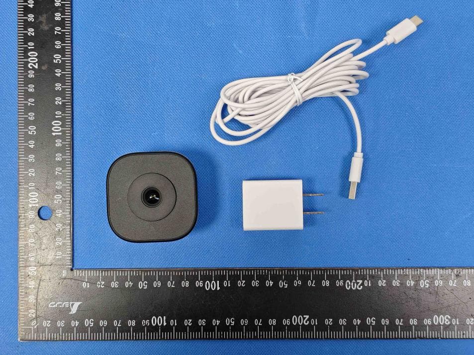
X4YHACIF25W
Aug 06, 2026Smart Camera
Equipment Class
DTS - Digital Transmission System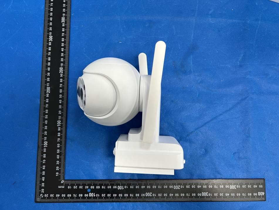
X4YHACOP40SL
Jul 07, 2026Smart Camera
Equipment Class
PCB - PCS Licensed Transmitter
X4YHABXL20
Jan 14, 2026Xmas string lights
Equipment Class
DTS - Digital Transmission System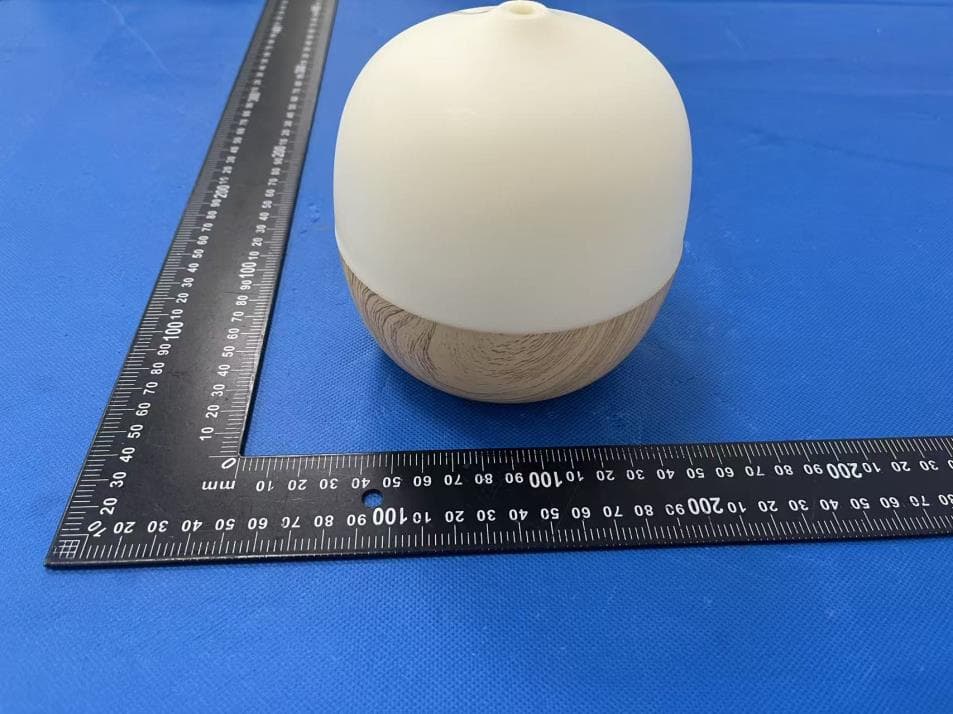
X4YHAAD300
Jan 06, 2026AROMA DIFFUSER
Equipment Class
DTS - Digital Transmission System
X4YHACIP15
Sep 28, 2025Camera
Equipment Class
DTS - Digital Transmission System