X4YNXG150NexxtGate 150 High Power Access Point
NEXXT SOLUTIONS
Click to zoom
Application Details
- Equipment Class
- DTS - Digital Transmission System
- Date of Grant
- Jan 27, 2015
- Application Purpose
- Original Equipment
- Date of Application
- Jan 27, 2015
- Equipment Note
- NexxtGate 150 High Power Access Point
- Frequency Range
- 2412.00000000 - 2462.00000000
- Company
- NEXXT SOLUTIONS
- Country
- United States
Documents & Files
Document Text
Text extracted from the exhibit documents filed with the FCC. Open a document above to read the original.
Users Manual
Nexxt Solutions - NexxtGate150 Access Point Quick Installation Guide 1. Introduction Thank you for purchasing the Nexxt Solutions 2 .4 GHz High-Power Wireless-N Access Point NexxtGate150. If any of the following items are mismatched, missing or damaged, please contact the merchant from whom you purchased the unit for immediate replacement. • 150Mbps wireless long-range access point 1 pc • Power adapter 1 pc ·~~~~~ 1~ • ne wraps 2 pcs • Passive PoE injector 1 pc • Screws and anchors 2 pcs each • Grounding screw 1 pc • Quick installation guide 2. Product overview 2.1 Front view layout and connectors Please refer to the figure below to familiarize yourself with the access point's layout, features and connectors. 2 Nexxt Solutions - NexxtGate150 Access Point 1. Ground: Attach a copper wire here to establish a good earth ground and to provide the proper surge and lightning protection. 2. SMAIQc This is a RP-SMA jack to connect an optional external antenna 3. LAN: This is a 10/100Mbps LAN port 4. LAN/WAN/POE: This port provides Power over an Ethernet connection through the injector module, and it works interchangeably as a WAN port in router mode end as a LAN port in AP mode. 5. Cable access hole cut-outs. 2.2 Injector overview •LAN/WAN: 1 OOMbps Ethernet port. • PDE: Power over Ethernet port. • Reset: Press it for 8-10 seconds to restore device to factory its default settings. •Power: DC input jack. 3 Nexxt Solutions - NexxtGate150 Access Point 2.3 Rear view LED status indicator panel LED Status PWR Solid orange light Solid orange light WAN/LAN Blinking orange light Solid orange light LAN Blinking orange light Orange WLAN Pink Red 4 Slip resistant pole/well mounting brackets Description The device is connected to the power source An Ethernet cable is connected Data is being transmitted through that port An Ethernet cable is connected Data is being transmitted through that port Maximum power is used to broadcast the wireless signal Medium power is used to broadcast the wireless signal Low power is used to broadcast the wireless signal Nexxt Solutions - NexxtGate150 Access Point 2.4 Checking the LEDs Upon powering on your access point. verify that the PWR and WlAN LEDs light up orange. 3. Location of the access point Before making any hardware connections, find a suitable location to place the access point. The best spot is usually at the center of the wireless network, with unobstructed line-of-sight to all wireless clients operating in the coverage area. Also consider that the higher the antenna is placed, the better the device can perform. Do not forget to make sure that the structure or pole you use to install the device is stable and properly secured. 1. If setting up the device in an indoor installation, use the keyholes on the brackets to mark the location on the wall where the access point is to be mounted. 2. Drill the holes and then drive the supplied anchors [if required] and screws into the wall. Leave the head of the screw slighgtly above the surface to hang the access point from the keyholes on the back. wall 5 Nexxt Solutions - NexxtGate150 Access Point 3. If setting up the device in an outdoor location, thread the tie wraps trough the grooves underneath the brackets. Then attach the device firmly to the pole. The connection will be similar to the figure below, once the above steps have been successfully completed. pole 4. Herdwere installation 1. Slide the bottom cover of the unit down to expose the ports. 2. In order to integrate your new wireless access point into your installation, start by plugging one end of an Ethernet cable to the PoE port of the supplied injector module, and the other end of the cable to the LAN/ WAN/POE port on the access point. 3. Use a second Ethernet cable to make the connection between the LAN port of the PoE module and your computer. 4. Replace the cover by sliding it up it until it clicks in place. 5. Power the device by plugging the included AC power adapter to DC jack on the PoE unit, and the other end into a standard wall outlet. 6 Nexxt Solutions - Ne:xxtGate150 Access Point 5. Initial configuration Note: only a wired network connection can be used for the initial configuration of the access point. Since this this device operates in AP mode by default, the user needs to manually configure a static IP address for the PC. 1. To do so, click on Start> Control Panel> Network and Internet> Network and Sharing Center, followed by Change adapter settings. 2.After right-clicking on the Local Area Connection, select Properties. Local Area Connection Di sable Status Diagnose B ridge Connections Create Shortcut Delete Rename Properti es 7 Nexxt Solutions - NexxtGate150 Access Point 3.Select Internet Protocol Version 4 [TCP/1Pv4) and then go to Properties. You may also enable this option directly by double-<:licking on Internet Protocol Version 4 [TCP/1Pv4). Local Area Connectio n 2 Properties Networking ~S_h_a•_;n~g~-------------~ Connect using: rfj Reattek RTL8139/810xfamily fast Ethernet NIC This connection uses the following items: ~ :.L Client for Microsoft Networks ~ maoS Packet Scheduler ~ ~File and Printer Sharing for Microsoft: Networks ~ ...... Internet Prot ocol Version 6 (TCP/1Pv6) ~ .... I Internet Protocol Version 4 (TCP/1Pv4) I Configure ... ~ ...._ link-layer T apology Discovery Mapper VO Driver ~ ..... Link-Layer Topology Discovery Responder ~--ln_st_al_L. __ ] LUnmstall Properties Description Transmission Control Protocol/lntemetProtocoL The default wide area network protocol that provides communication across d iverse interconnected networks. OK 11 Cancel 4.0nce the next dialog box comes up, select Use the following IP address option. The following items will become available: •IP address: Enter 192. 168.0. XXX (whereby X is any number between 2-253). •Subnet mask: Enter 255.255.255.0. 8 Nexxt Solutions - NexxtGate150 Access Point 5.Click OK twice to save your settings and complete the IP address configuration of the device. 5.1 Login 1…
Text truncated - open the document above for the full version.
External Photos
Project No.: 1411C285 Page 2 of 16 Project No.: 1411C285 Page 3 of 16 Project No.: 1411C285 Page 4 of 16 Project No.: 1411C285 Page 5 of 16 Project No.: 1411C285 Page 6 of 16 Project No.: 1411C285 Page 7 of 16 Project No.: 1411C285 Page 8 of 16 Project No.: 1411C285 Page 9 of 16
Internal Photos
Project No.: 1411C285 Page 10 of 16 Project No.: 1411C285 Page 11 of 16 Project No.: 1411C285 Page 12 of 16 Project No.: 1411C285 Page 13 of 16 Project No.: 1411C285 Page 14 of 16 Project No.: 1411C285 Page 15 of 16 Project No.: 1411C285 Page 16 of 16
RF Exposure Info
FCC RF EXPOSURE REPORT FCC ID: X4YNXG150 Project 1411C285 Equipment : NexxtGate 150 High Power Access Point Model : AEOPLDR4U2 Applicant : NEXXT SOLUTIONS Address : 3505 N.W MIAMI, FL, 33178 According: : FCC Guidelines for Human Exposure IEEE C95.1 BTL INC. No.3, Jinshagang 1st Road, Shixia, Dalang Town, Dongguan, China. TEL: +86-769-8318-3000 FAX: +86-769-8319-6000 MPE CALCULATION METHOD: Calculation Method of RF Safety Distance: where: S = power density P = power input to the a ntenna G = power gain of the antenna in the direction of interest relative to an isotropic radiato r R = distance to the center of radiation of the antenna Table for Filed Antenna Ant. Brand Model Name Antenna TypeConnectorGain(dBi) Note 1 N/A N/A Internal N/A 10.00 TX/RX 2 Tenda Q5091 Dipole N/A 5.07 TX/RX Note: Antenna 1 and antenna 2 is optional. Only one antenna is used at a time. These two antennas can not transmit simultaneously. TEST RESULTS EUT: ExxtGate 150 High Power Access Point Model Name : AEOPLDR4U2 Temperature: 25 °C Relative Humidity: 55 % Test Voltage : AC 120V/60Hz Test Mode : TX B MODE_Ant 1 /CH01, CH06, CH11 Antenna Gain (dBi) Antenna Gain (numeric) Peak Output Power (dBm) Peak Output Power (mW) Power Density (S) (mW/cm 2 ) Limit of Power Density (S) (mW/cm 2 ) Te s t Result 10.00 10.0000 18.75 74.9894 0.149262381 Complies 10.00 10.0000 18.56 71.7794 0.142873071 Complies 10.00 10.0000 15.70 37.1535 0.073952081 Complies EUT: ExxtGate 150 High Power Access Point Model Name : AEOPLDR4U2 Temperature: 25 °C Relative Humidity: 55 % Test Voltage : AC 120V/60Hz Test Mode : TX G MODE_Ant 1/CH01, CH06, CH11 Antenna Gain (dBi) Antenna Gain (numeric) Peak Output Power (dBm) Peak Output Power (mW) Power Density (S) (mW/cm 2 ) Limit of Power Density (S) (mW/cm 2 ) Te s t Result 10.00 10.0000 22.60 181.9701 0.362201601 Complies 10.00 10.0000 25.30 338.8442 0.674450951 Complies 10.00 10.0000 20.50 112.2018 0.223331701 Complies EUT: ExxtGate 150 High Power Access Point Model Name : AEOPLDR4U2 Temperature: 25 °C Relative Humidity: 55 % Test Voltage : AC 120V/60Hz Test Mode : TX N-20M MODE_Ant 1 /CH01, CH06, CH11 Antenna Gain (dBi) Antenna Gain (numeric) Peak Output Power (dBm) Peak Output Power (mW) Power Density (S) (mW/cm 2 ) Limit of Power Density (S) (mW/cm 2 ) Te s t Result 10.00 10.0000 19.10 81.2831 0.161789511 Complies 10.00 10.0000 23.00 199.5262 0.397146161 Complies 10.00 10.0000 19.60 91.2011 0.181530821 Complies EUT: ExxtGate 150 High Power Access Point Model Name : AEOPLDR4U2 Temperature: 25 °C Relative Humidity: 55 % Test Voltage : AC 120V/60Hz Test Mode : TX N-40M MODE_Ant 1/CH03, CH06, CH09 Antenna Gain (dBi) Antenna Gain (numeric) Peak Output Power (dBm) Peak Output Power (mW) Power Density (S) (mW/cm 2 ) Limit of Power Density (S) (mW/cm 2 ) Te s t Result 10.00 10.0000 19.80 95.4993 0.190086101 Complies 10.00 10.0000 21.10 128.8250 0.256419101 Complies 10.00 10.0000 16.90 48.9779 0.097487821 Complies Note: 1)Antenna 1 has the higher gain so it is recorded as the worst case. 2)The calculated distance is 20 cm.
Test Report
Report No.: BTL-FCCP-1-1411C285 Page 1 of 188 FCC Radio Test Report FCC ID: X4YNXG150 This report concerns (check one): Original Grant Class II Change Project No. : 1411C285 Equipment : NexxtGate 150 High Power Access Point Model Name : AEOPLDR4U2 Applicant : NEXXT SOLUTIONS Address : 3505 N.W 107TH AVE,MIAMI ,FL,33178 Date of Receipt : Dec. 01, 2014 Date of Test : Dec. 01, 2014 ~ Dec. 18, 2014 Issued Date : Dec. 19, 2014 Tested by : BTL Inc. Testing Engineer : (David Mao) Technical Manager : (Leo Hung) Authorized Signatory : (Steven Lu) BTL INC. No.3, Jinshagang 1st Road, Shixia, Dalang Town, Dongguan, Guangdong, China. TEL: +86-769-8318-3000 FAX: +86-769-8319-6000 Report No.: BTL-FCCP-1-1411C285 Page 2 of 188 Declaration BTL represents to the client that testing is done in accordance with standard proced ures as applicable and that test instruments used has been calibrated with the standards traceable to National Measurement Laboratory (NML) of R.O.C, or National Institute of Standards and Technology (NIST) of U.S.A. BTL's reports apply only to the specific samples tested under conditions. It is manufacture’s responsibility to ensure that additional production units of this model are manufactured with the identical electrical and mechanical components. BTL shall have no liability for any declarations, inferences or generalizations drawn by the client or others from BTL issued reports. BTL’s reports must not be used by the client to claim product endorsement by the authorities or any agency of the Government. This report is the confidential property of the client. As a mutual protection to the clients, the public and BTL-self, extracts from the test report shall not be reproduced except in full with BTL’s authorized written approval. BTL’s laboratory quality assurance procedures are in compliance with the ISO Guide 17025 requirements, and accredited by the conformity assessment authorities listed in this test report. Limitation For the use of the authority's logo is limited unless the Test Standard(s)/Scope(s)/Item(s) mentioned in this test report is (are) included in the conformity assessment authorities acceptance respective. Report No.: BTL-FCCP-1-1411C285 Page 3 of 188 Table of Contents Page 1 . CERTIFICATION 6 2 . SUMMARY OF TEST RESULTS 7 2.1 TEST FACILITY 8 2.2 MEASUREMENT UNCERTAINTY 8 3 . GENERAL INFORMATION 9 3.1 GENERAL DESCRIPTION OF EUT 9 3.2 DESCRIPTION OF TEST MODES 11 3.3 TABLE OF PARAMETERS OF TEXT SOFTWARE SETTING 12 3.4 BLOCK DIAGRAM SHOWING THE CONFIGURATION OF SYSTEM TESTED 13 3.5 DESCRIPTION OF SUPPORT UNITS 13 4 . EMC EMISSION TEST 14 4.1 CONDUCTED EMISSION MEASUREMENT 14 4.1.1 POWER LINE CONDUCTED EMISSION LIMITS 14 4.1.2 TEST PROCEDURE 14 4.1.3 DEVIATION FROM TEST STANDARD 14 4.1.4 TEST SETUP 15 4.1.5 EUT OPERATING CONDITIONS 15 4.1.6 EUT TEST CONDITIONS 15 4.1.7 TEST RESULTS 15 4.2 RADIATED EMISSION MEASUREMENT 16 4.2.1 RADIATED EMISSION LIMITS 16 4.2.2 TEST PROCEDURE 17 4.2.3 DEVIATION FROM TEST STANDARD 17 4.2.4 TEST SETUP 17 4.2.5 EUT OPERATING CONDITIONS 18 4.2.6 EUT TEST CONDITIONS 18 4.2.7 TEST RESULTS (9KHZ TO 30MHZ) 19 4.2.8 TEST RESULTS (BETWEEN 30MHZ TO 1000 MHZ) 19 4.2.9 TEST RESULTS (ABOVE 1000 MHZ) 19 5 . BANDWIDTH TEST 20 5.1 APPLIED PROCEDURES 20 5.1.1 TEST PROCEDURE 20 5.1.2 DEVIATION FROM STANDARD 20 5.1.3 TEST SETUP 20 5.1.4 EUT OPERATION CONDITIONS 20 5.1.5 EUT TEST CONDITIONS 20 5.1.6 TEST RESULTS 20 Report No.: BTL-FCCP-1-1411C285 Page 4 of 188 Table of Contents Page 6 . MAXIMUM PEAK CONDUCTED OUTPUT POWER TEST 21 6.1 APPLIED PROCEDURES / LIMIT 21 6.1.1 TEST PROCEDURE 21 6.1.2 DEVIATION FROM STANDARD 21 6.1.3 TEST SETUP 21 6.1.4 EUT OPERATION CONDITIONS 21 6.1.5 EUT TEST CONDITIONS 21 6.1.6 TEST RESULTS 21 7 . ANTENNA CONDUCTED SPURIOUS EMISSION 22 7.1 APPLIED PROCEDURES / LIMIT 22 7.1.1 TEST PROCEDURE 22 7.1.2 DEVIATION FROM STANDARD 22 7.1.3 TEST SETUP 22 7.1.4 EUT OPERATION CONDITIONS 22 7.1.5 EUT TEST CONDITIONS 22 7.1.6 TEST RESULTS 22 8 . POWER SPECTRAL DENSITY TEST 23 8.1 APPLIED PROCEDURES / LIMIT 23 8.1.1 TEST PROCEDURE 23 8.1.2 DEVIATION FROM STANDARD 23 8.1.3 TEST SETUP 23 8.1.4 EUT OPERATION CONDITIONS 23 8.1.5 EUT TEST CONDITIONS 23 8.1.6 TEST RESULTS 23 9 . MEASUREMENT INSTRUMENTS LIST 24 10 . EUT TEST PHOTO 26 ATTACHMENT A - CONDUCTED EMISSION 34 ATTACHMENT B - RADIATED EMISSION (9KHZ TO 30MHZ) 39 ATTACHMENT C - RADIATED EMISSION (30MHZ TO 1000MHZ) 42 ATTACHMENT D - RADIATED EMISSION (ABOVE 1000MHZ) 55 ATTACHMENT E - BANDWIDTH 152 ATTACHMENT F – MAXIMUM PEAK CONDUCTED OUTPUT POWER 161 ATTACHMENT G - ANTENNA CONDUCTED SPURIOUS EMISSION 163 ATTACHMENT H - POWER SPECTRAL DENSITY 180 Report No.: BTL-FCCP-1-1411C285 Page 5 of 188 REPORT ISSUED HISTORY Issued No. Description Issued Date BTL-FCCP-1-1411C285 Original Issue. Dec. 19, 2014 Report No.: BTL-FCCP-1-1411C285 Page 6 of 188 1. CERTIFICATION Equipment : NexxtGate 150 High Power Access Point Brand Name : NEXXT Model Name : AEOPLDR4U2 Applicant : NEXXT SOLUTIONS Date of Test : Dec. 01, 2014 ~ Dec. 18, 2014 Test Sample : ENGINEERING SAMPLE Standard(s) : FCC Part15, Subpart C: 2013 (15.247) / ANSI C63.4-2009 The above equipment has been tested and found compliance with the requirement of the relative standards by BTL Inc. The test data, data evaluation, and equipment configuration contained in our test report (Ref No. BTL-FCCP-1-1411C285) were obtained utilizing the test procedures, test instruments, test sites that has been accredited by the Authority of TAF according to the ISO-17025 quality assessment standard and technical standard(s). Report No.: BTL-FCCP-1-1411C285 Page 7 of 188 2. SUMMARY OF TEST RESULTS Test procedures according to the technical standard(s): Applied Standard(s): FCC Part15 (15.247) , Subpart C: 2013 Standard(s) Section Test Item Judgment Remark FCC 15.207 Conducted Emission PASS 15.247(d) Antenna conducted Spurious Emission PASS 15.247(a)(2) 6dB Bandwidth PASS 15.247(b)(3) Peak Output Power PASS 15.247(e) Power Spectral Density PASS 15.203 Antenna Require…
Text truncated - open the document above for the full version.
Test Report
Report No.: BTL-FCCP-1-1411C285 Page 101 of 188 Orthogonal Axis : X Test Mode : TX N-40M MODE 2452MHz-Internal Antenna Vertical Report No.: BTL-FCCP-1-1411C285 Page 102 of 188 Orthogonal Axis : X Test Mode : TX N-40M MODE 2452MHz-Internal Antenna Horizontal Report No.: BTL-FCCP-1-1411C285 Page 103 of 188 Orthogonal Axis : X Test Mode : TX N-40M MODE 2452MHz-Internal Antenna Horizontal Report No.: BTL-FCCP-1-1411C285 Page 104 of 188 Orthogonal Axis : X Test Mode : TX B MODE 2412MHz-External Antenna Vertical Report No.: BTL-FCCP-1-1411C285 Page 105 of 188 Orthogonal Axis : X Test Mode : TX B MODE 2412MHz-External Antenna Vertical Report No.: BTL-FCCP-1-1411C285 Page 106 of 188 Orthogonal Axis : X Test Mode : TX B MODE 2412MHz-External Antenna Horizontal Report No.: BTL-FCCP-1-1411C285 Page 107 of 188 Orthogonal Axis : X Test Mode : TX B MODE 2412MHz-External Antenna Horizontal Report No.: BTL-FCCP-1-1411C285 Page 108 of 188 Orthogonal Axis : X Test Mode : TX B MODE 2437MHz-External Antenna Vertical Report No.: BTL-FCCP-1-1411C285 Page 109 of 188 Orthogonal Axis : X Test Mode : TX B MODE 2437MHz-External Antenna Vertical Report No.: BTL-FCCP-1-1411C285 Page 110 of 188 Orthogonal Axis : X Test Mode : TX B MODE 2437MHz-External Antenna Horizontal Report No.: BTL-FCCP-1-1411C285 Page 111 of 188 Orthogonal Axis : X Test Mode : TX B MODE 2437MHz-External Antenna Horizontal Report No.: BTL-FCCP-1-1411C285 Page 112 of 188 Orthogonal Axis : X Test Mode : TX B MODE 2462MHz-External Antenna Vertical Report No.: BTL-FCCP-1-1411C285 Page 113 of 188 Orthogonal Axis : X Test Mode : TX B MODE 2462MHz-External Antenna Vertical Report No.: BTL-FCCP-1-1411C285 Page 114 of 188 Orthogonal Axis : X Test Mode : TX B MODE 2462MHz-External Antenna Horizontal Report No.: BTL-FCCP-1-1411C285 Page 115 of 188 Orthogonal Axis : X Test Mode : TX B MODE 2462MHz-External Antenna Horizontal Report No.: BTL-FCCP-1-1411C285 Page 116 of 188 Orthogonal Axis : X Test Mode : TX G MODE 2412MHz-External Antenna Vertical Report No.: BTL-FCCP-1-1411C285 Page 117 of 188 Orthogonal Axis : X Test Mode : TX G MODE 2412MHz-External Antenna Vertical Report No.: BTL-FCCP-1-1411C285 Page 118 of 188 Orthogonal Axis : X Test Mode : TX G MODE 2412MHz-External Antenna Horizontal Report No.: BTL-FCCP-1-1411C285 Page 119 of 188 Orthogonal Axis : X Test Mode : TX G MODE 2412MHz-External Antenna Horizontal Report No.: BTL-FCCP-1-1411C285 Page 120 of 188 Orthogonal Axis : X Test Mode : TX G MODE 2437MHz-External Antenna Vertical Report No.: BTL-FCCP-1-1411C285 Page 121 of 188 Orthogonal Axis : X Test Mode : TX G MODE 2437MHz-External Antenna Vertical Report No.: BTL-FCCP-1-1411C285 Page 122 of 188 Orthogonal Axis : X Test Mode : TX G MODE 2437MHz-External Antenna Horizontal Report No.: BTL-FCCP-1-1411C285 Page 123 of 188 Orthogonal Axis : X Test Mode : TX G MODE 2437MHz-External Antenna Horizontal Report No.: BTL-FCCP-1-1411C285 Page 124 of 188 Orthogonal Axis : X Test Mode : TX G MODE 2462MHz-External Antenna Vertical Report No.: BTL-FCCP-1-1411C285 Page 125 of 188 Orthogonal Axis : X Test Mode : TX G MODE 2462MHz-External Antenna Vertical Report No.: BTL-FCCP-1-1411C285 Page 126 of 188 Orthogonal Axis : X Test Mode : TX G MODE 2462MHz-External Antenna Horizontal Report No.: BTL-FCCP-1-1411C285 Page 127 of 188 Orthogonal Axis : X Test Mode : TX G MODE 2462MHz-External Antenna Horizontal Report No.: BTL-FCCP-1-1411C285 Page 128 of 188 Orthogonal Axis : X Test Mode : TX N-20M MODE 2412MHz-External Antenna Vertical Report No.: BTL-FCCP-1-1411C285 Page 129 of 188 Orthogonal Axis : X Test Mode : TX N-20M MODE 2412MHz-External Antenna Vertical Report No.: BTL-FCCP-1-1411C285 Page 130 of 188 Orthogonal Axis : X Test Mode : TX N-20M MODE 2412MHz-External Antenna Horizontal Report No.: BTL-FCCP-1-1411C285 Page 131 of 188 Orthogonal Axis : X Test Mode : TX N-20M MODE 2412MHz-External Antenna Horizontal Report No.: BTL-FCCP-1-1411C285 Page 132 of 188 Orthogonal Axis : X Test Mode : TX N-20M MODE 2437MHz-External Antenna Vertical Report No.: BTL-FCCP-1-1411C285 Page 133 of 188 Orthogonal Axis : X Test Mode : TX N-20M MODE 2437MHz-External Antenna Vertical Report No.: BTL-FCCP-1-1411C285 Page 134 of 188 Orthogonal Axis : X Test Mode : TX N-20M MODE 2437MHz-External Antenna Horizontal Report No.: BTL-FCCP-1-1411C285 Page 135 of 188 Orthogonal Axis : X Test Mode : TX N-20M MODE 2437MHz-External Antenna Horizontal Report No.: BTL-FCCP-1-1411C285 Page 136 of 188 Orthogonal Axis : X Test Mode : TX N-20M MODE 2462MHz-External Antenna Vertical Report No.: BTL-FCCP-1-1411C285 Page 137 of 188 Orthogonal Axis : X Test Mode : TX N-20M MODE 2462MHz-External Antenna Vertical Report No.: BTL-FCCP-1-1411C285 Page 138 of 188 Orthogonal Axis : X Test Mode : TX N-20M MODE 2462MHz-External Antenna Horizontal Report No.: BTL-FCCP-1-1411C285 Page 139 of 188 Orthogonal Axis : X Test Mode : TX N-20M MODE 2462MHz-External Antenna Horizontal Report No.: BTL-FCCP-1-1411C285 Page 140 of 188 Orthogonal Axis : X Test Mode : TX N-40M MODE 2422MHz-External Antenna Vertical Report No.: BTL-FCCP-1-1411C285 Page 141 of 188 Orthogonal Axis : X Test Mode : TX N-40M MODE 2422MHz-External Antenna Vertical Report No.: BTL-FCCP-1-1411C285 Page 142 of 188 Orthogonal Axis : X Test Mode : TX N-40M MODE 2422MHz-External Antenna Horizontal Report No.: BTL-FCCP-1-1411C285 Page 143 of 188 Orthogonal Axis : X Test Mode : TX N-40M MODE 2422MHz-External Antenna Horizontal Report No.: BTL-FCCP-1-1411C285 Page 144 of 188 Orthogonal Axis : X Test Mode : TX N-40M MODE 2437MHz-External Antenna Vertical Report No.: BTL-FCCP-1-1411C285 Page 145 of 188 Orthogonal Axis : X Test Mode : TX N-40M MODE 2437MHz-External Antenna Vertical Report No.: BTL-FCCP-1-1411C285 Page 146 of 188 Orthogonal Axis : X Test Mode : TX N-40M MODE 2437MHz-External Antenna Horizontal Report No.: BTL-FCCP-1-1411C285 Page 147 of 188 Orthogonal Axis : X Test Mode : TX N-40M MODE 2437MHz-External Antenna Horizontal Report No.: BTL-FCCP-1-1411C285 …
Text truncated - open the document above for the full version.
Test Setup Photos
Report No.: BTL-FCCP-1-1411C285 Page 26 of 188 10. EUT TEST PHOTO Conducted Measurement Photos-Internal Antenna Report No.: BTL-FCCP-1-1411C285 Page 27 of 188 Conducted Measurement Photos-External Antenna Report No.: BTL-FCCP-1-1411C285 Page 28 of 188 Radiated Measurement Photos-Internal Antenna 9KHz to 30MHz Report No.: BTL-FCCP-1-1411C285 Page 29 of 188 Radiated Measurement Photos-Internal Antenna 30MHz to 1000MHz Report No.: BTL-FCCP-1-1411C285 Page 30 of 188 Radiated Measurement Photos-Internal Antenna Above 1000MHz Report No.: BTL-FCCP-1-1411C285 Page 31 of 188 Radiated Measurement Photos-External Antenna 9KHz to 30MHz Report No.: BTL-FCCP-1-1411C285 Page 32 of 188 Radiated Measurement Photos-External Antenna 30MHz to 1000MHz Report No.: BTL-FCCP-1-1411C285 Page 33 of 188 Radiated Measurement Photos-External Antenna Above 1000MHz
Contact Information
Applicant
Albert Mizrachi(Vice president of product development)
Test Firm
BTL Inc.Daisy Dai
Technical Specifications
| # | Rule Parts | Frequency Range | Power Output |
|---|---|---|---|
| 1 | 15C | 2.41 GHz - 2.46 GHz | 338.80 mW |
Other Applications from NEXXT SOLUTIONS
X4YHACIF25W
Aug 06, 2026Smart Camera
Equipment Class
DTS - Digital Transmission System
X4YHACOP40SL
Jul 07, 2026Smart Camera
Equipment Class
PCB - PCS Licensed Transmitter
X4YHABXL20
Jan 14, 2026Xmas string lights
Equipment Class
DTS - Digital Transmission System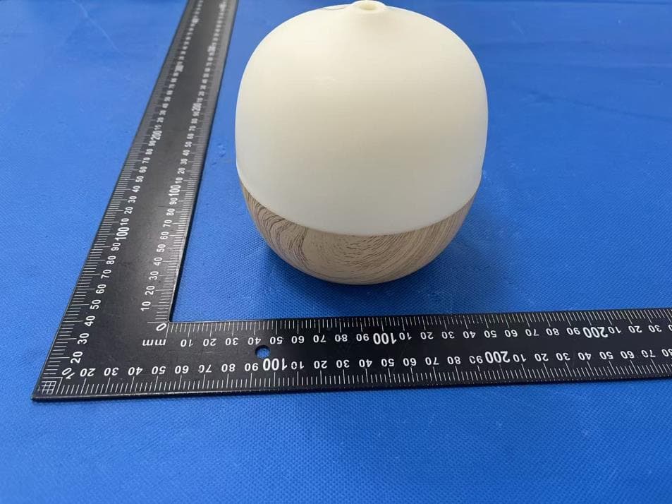
X4YHAAD300
Jan 06, 2026AROMA DIFFUSER
Equipment Class
DTS - Digital Transmission System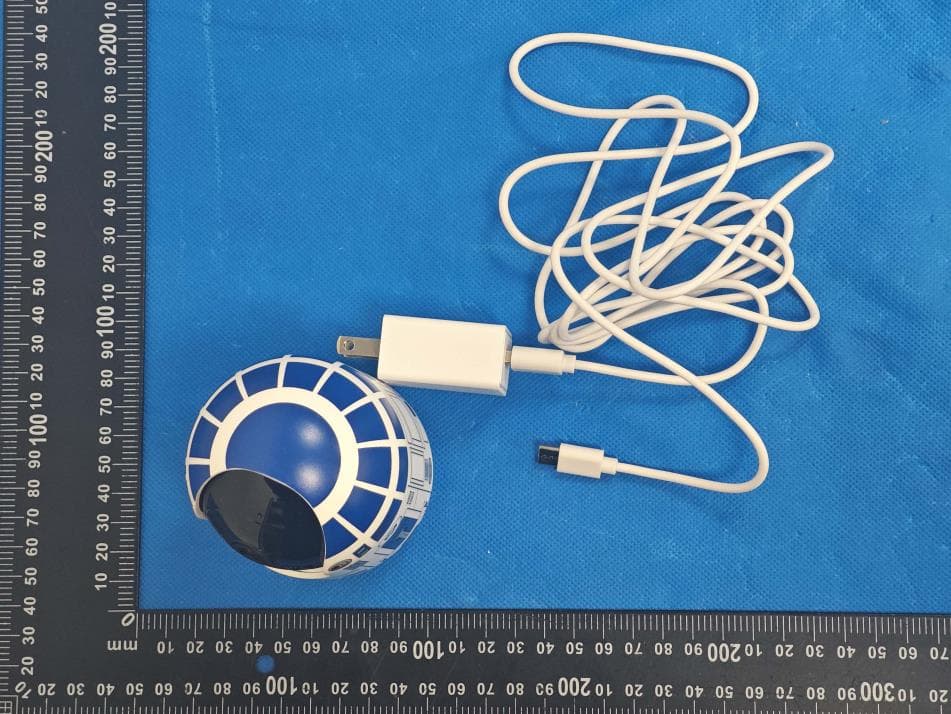
X4YHACIP15
Sep 28, 2025Camera
Equipment Class
DTS - Digital Transmission System