X4YRMI4U1Wireless Baby Camera
NEXXT SOLUTIONS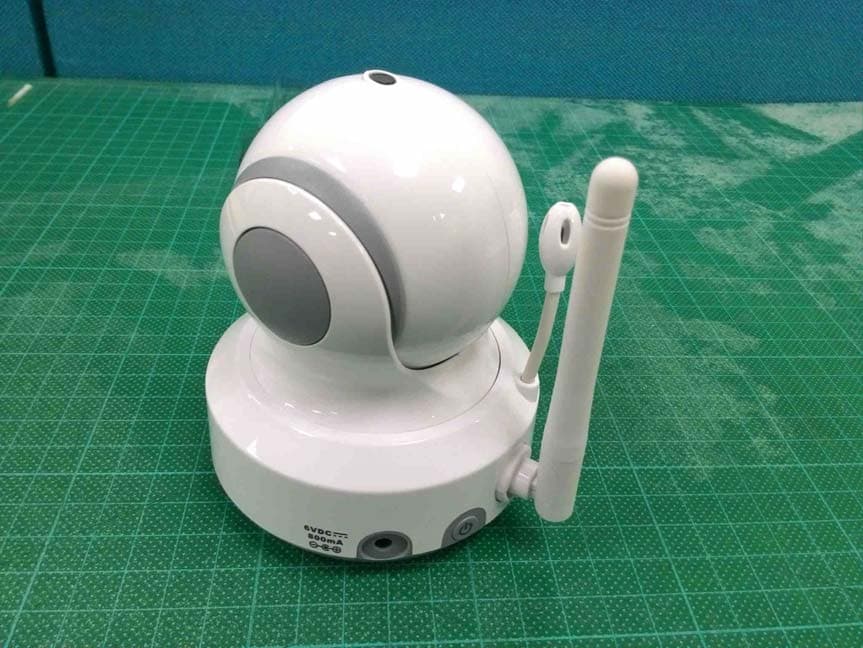
Click to zoom
Application Details
- Equipment Class
- DSS - Part 15 Spread Spectrum Transmitter
- Date of Grant
- Nov 22, 2015
- Application Purpose
- Original Equipment
- Date of Application
- Nov 22, 2015
- Equipment Note
- Wireless Baby Camera
- Frequency Range
- 2408.00000000 - 2468.00000000
- Company
- NEXXT SOLUTIONS
- Country
- United States
Documents & Files
Document Text
Text extracted from the exhibit documents filed with the FCC. Open a document above to read the original.
Users Manual
User's Manual Manuel de l'utilisateur Manual del Usuario Bedienungsanleitung Manuale d'uso 3.5 '' Pan-Tilt Wireless Video Baby Monitor E N G L I S H E S P A Ñ O L D E U T S C H I T A L I A N O F R A N Ç A I S Product Layout / Description du produit / Esquema del producto / Produktübersicht / Struttura del prodotto Figures and Quick Guide / Figures et Guide d'utilisation rapide / Figuras y guía rápida / Abbildungen und Schnellanleitung / Figure e Guida rapida Camera / Caméra / Cámara / Kamera / Telecamera Fig. 1 i Monitor / Moniteur Fig. 2 19 1718 1213141516 10 6 7 89 1 2 3 4 5 11 10 9 6 5 3 7 8 2 4 1 Setup / Installation / Configuración / Einrichtung / Installazione 1 Fig. 3 ii Camera Setup / Installation de la caméra / Configuración de la cámara / Kameraeinrichtung / Installazione della telecamera 1.1 Power Supply - Using AC Power Alimentation - Avec alimentation secteur Fuente de alimentación - Utilizar la alimentación de CA Stromversorgung – über Netzstrom Alimentazione - Uso dell'alimentazione CA Fig. 4 3 iii 2 Monitor Setup / Installation du moniteur / Configuración del monitor / Monitoreinrichtung / Installazione del monitor Power Supply / Alimentation / Fuente de alimentación / Stromversorgung / Alimentazione 2.1 Loading the Battery / Installation de la batterie / Insertar las pilas / Akku einlegen / Inserimento delle batterie Using AC Power/Utilisation de l'alimentation secteur / Uso de la alimentación de CA / Netzstrom verwenden / Uso dell'alimentazione CA Out of Range Fig. 5 1 2 3 11 2 Pan Tilt iv 2.4 VOX (Voice-Operated Transmission) Function Fonction TCV (Transmission de Commande Vocale) Función VOX (transmisión de activación por voz) VOX-Funktion (geräuschaktivierte Übertragung) Funzione VOX (trasmissione attivata a voce) 2.3 Zoom in Function / Fonction de zoom / Función de zoom de ampliación / Vergrößern-Funktion / Funzione ingrandimento 2.2 Monitor Remote Control Function Fonction télécommande du moniteur Función del mando a distancia del monitor Monitorfernbedienungsfunktion Funzioni del telecomando del monitor Fig. 6 Fig. 7 Fig. 8 v 2.5 Volume Setting / Réglage du volume / Configuración del volumen / Lautstärkeeinstellung / Impostazione del volume 2.6 Talkback Function / Fonction de réponse / Función de intercomunicador / Gegensprechfunktion / Funzione interfono Fig. 10 Fig. 9 vi 3 Menu Options / Options du menu / Opciones del menú / Menüoptionen / Opzioni del menu 3.2 Feed Timer Setting / Paramètre du minuteur d'alimentation / Configuración del temporizador de fuentes / Fütterungstimer-Einstellung / Impostazione timer alimentazione Fig. 13 3.1 Camera Selection / Sélection de la caméra / Selección de la cámara / Kameraauswahl / Selezione telecamera Fig. 12 Fig. 11 vii Temperature Setting / Réglage de la température / Configuración de la temperatura / Temperatureinstellung / Impostazione temperatura 3.3 3.5 Brightness Setting / Réglage de la luminosité / Configuración del brillo / Helligkeitseinstellung / Impostazione della luminosità Fig. 16 Fig. 14 3.4 Camera Setting / Paramètre caméra / Configuración de la cámara / Kameraeinstellung / Impostazione videocamera Fig. 15 viii Fig. 17 VOX Sensitivity / Sensibilité VOX / Sensibilidad de VOX / VOX-Empfindlichkeit / Sensibilità VOX 3.6 Fig. 18 4 Status Information / / / / Informations de statut Información de estadoStatusinformationen Informazioni di stato 23456781 1 Package Contents One Monitor Two Power Adapters Battery for Monitor ( 3.7V 1100mAH Li-ion ) Two Cable Clips One Screw and One Wall Anchor This User's Manual Product Layout Camera (Fig. 1) 1. Light sensor 2. Microphone 3. Lens 4. Infrared LEDs 5. Speaker 6. Power adapter plug 7. Power/Pairing button 8. Antenna 9. Temperature sensor 10. Power indicator LED Monitor (Fig. 2) 1. LCD screen 2. Left button 3. Up button 4. Zoom/OK button 5. Right button 6. Down button 7. Speaker 8. Microphone 9. Power indicator LED 10. VOX indicator LED 11. Volume indicator LEDs 12. Power button 13. VOX button 14. Volume setup button 15. Talkback button 16. Menu button 17. Battery compartment 18. Holder 19. Power adapter plug One Camera E N G L I S H 2 Setup P 1.Plug one end of the provided power adapter into a wall outlet and the other end into the back of the camera. See Fig. 3. Note : Use the adapter labeled OUTPUT: 6V DC with the camera. 2.Press the POWER button and keep it around 3 seconds to turn on the monitor. The LED on the camera will light up (green light). See Fig. 3. Note : Press the POWER button and keep it around 3 seconds to turn off the monitor. Fine Tuning Place the camera in a convenient location, point the lens toward the observation area. Night Vision The camera has eight high-intensity LEDs for picking up clear images in the dark. When the light sensor detects low ambient light levels, the LEDs will be automatically activated. Room Temperature Measurement Temperature sensor can measure room temperature on camera side and the room temperature indicator will be displayed on the screen of the monitor unit. Camera Setup ower Supply - Using AC Power 1 1.1 1.2 1.3 1.4 Power Supply current. Loading the Battery 1.Open the battery compartment cover on the rear of the monitor. See Fig. 4. 2.Insert the battery with the metal facing the battery compartment. See Fig. 4. 3.Close the battery compartment cover, and make sure it is locked securely. 4.Press the POWER button and keep it around 3 seconds to turn the monitor on. See Fig. 4. Note 1: When power is sufficient, the "Power” LED will light up (green light); When battery is low, the red LED light will start blinking. Note 2: Press the POWER button and keep it around 3 seconds to turn off the monitor. Monitor Setup The monitor uses 3.7V 1100mAH (Li-ion) battery or the household AC power 2.1 2 3 1. into the monitor. See Fig. 5. Note : Use the adapter labeled OUTPUT: 6V DC with the monitor. 2.Press the POWER button and keep it around 3 seconds to turn the monitor on. See Fig. 5. Note 1: When power on the monitor, "Power" LED will …
Text truncated - open the document above for the full version.
Cover Letter(s)
2015-11-23
Cover Letter(s)
Nexxt Solution Confidentiality Letter (Permanent) Attention: Application Examiner Re: Request for confidentiality Applicant: Nexxt Solutions FCC ID: X4YRMI4U1 To whom it may concern, Request is hereby submitted by Gao Jin Industrial Co., Ltd. to withhold permanently from public review certain portions of the application for equipment certification for the referenced FCC identifiers. This request for confidentiality is made pursuant to 47 CFR 0.457(d) of the FCC Rules. In particular, the following sections of the application are to be kept permanently confidential: • Schematics • Block Diagram • Operational Description Rationale for request for confidentiality: Nexxt Solutions has invested considerable time and materials in research and development to produce the referenced product. Disclosure of the permanently confidential portions of this application to competitors would not only give them significant competitive advantages in developing similar products, but would also disclose successful implementation of unpublished, leading edge technology developed by us. If you have questions or need further information, please contact the undersigned. Sincerely, Date: 2015-11-23
Cover Letter(s)
Nexxt Solutions Date: 2015/11/23 To: Federal Communications Commission 7435 Oakland Mills Road Columbia, MD FCC ID: X4YRMI4U1 To Whom It May Concern: This letter is to ascertain that Nexxt Soulations Product Wirless Baby Monitor, has been the units used for conducting FCC compliance testing, the DoC part will be tested by FCC recognized test lab. If you have any question or concerns, pls. contact us. Sincerely,
Cover Letter(s)
Nexxt Solutions Hopping Declaration Model no.: AIWPTFI4U1 Date: 2015/11/23 31 2408~2468
External Photos
External photo of EUT External photo of EUT External photo of EUT External photo of EUT
ID Label/Location Info
Lable Label Location
Internal Photos
Internal photo of EUT Internal photo of EUT Internal photo of EUT Internal photo of EUT Internal photo of EUT RF Module
RF Exposure Info
FCC ID.: X4YRMI4U1 Report No.:151000316TWN-001 Page 1 of 10 0597 Maximum Permissible Exposure (MPE) Evaluation Report Report No.: 151000316TWN-001 Model No.: AIWPTFI4U1 Issued Date: Oct. 30, 2015 Applicant: Nexxt Solutions 3505 N.W 107TH AVE. MIAMI, Florida 33178, United States Test Method/ Standard: FCC 1.1310 Test By: Intertek Testing Services Taiwan Ltd. No. 11, Lane 275, Ko-Nan 1 Street, Chia-Tung Li, Shiang-Shan District, Hsinchu City, Taiwan It may be duplicated completely for legal use with the allowance of the applicant. It shall not be reproduced except in full, without the written approval of Intertek Laboratory. The test result(s) in this report only applies to the tested sample(s). The test report was prepared by: Candy Liu / Assistant These measurements were taken by: Terry Hsu / Engineer The test report was reviewed by: Name Jimmy Yang Title Senior Engineer FCC ID.: X4YRMI4U1 Report No.:151000316TWN-001 Page 2 of 10 Table of Contents Summary of Tests ..............................................................................................................3 1. General information ......................................................................................................4 1.1 Identification of the EUT ........................................................................................4 1.2 Additional information about the EUT....................................................................5 1.3 Antenna description.................................................................................................5 1.4 Adapter information ................................................................................................5 1.5 Peripherals equipment .............................................................................................5 2. Test specifications .........................................................................................................6 2.1. Introduction ............................................................................................................6 2.2. RF Exposure Limit .................................................................................................7 2.3 RF Exposure calculations........................................................................................9 2.4 Operation mode .......................................................................................................9 2.5 Test equipment ........................................................................................................9 2.6 Test Set-up .............................................................................................................10 3. Test results ...................................................................................................................10 FCC ID.: X4YRMI4U1 Report No.:151000316TWN-001 Page 3 of 10 Summary of Tests MPE Evaluation meet FCC OET No. 65: 1997, IEEE C95.1-2005 Test Reference Results MPE Evaluation FCC Guidelines for Human Exposure IEEE C95.1 Complies FCC ID.: X4YRMI4U1 Report No.:151000316TWN-001 Page 4 of 10 1. General information 1.1 Identification of the EUT Product: Wireless Baby Camera Model No.: AIWPTFI4U1 FCC ID.: X4YRMI4U1 Frequency Range: 2408MHz~2468MHz Channel Number: 31 channels Frequency of Each Channel: 2408+2k, k=0~30 Type of Modulation: GFSK, FHSS Rated Power: DC 6 V from adapter Power Cord: N/A Sample Received: Jun. 13, 2013 Test Date(s): Jun. 24, 2013~Jul. 18, 2013 Note 1: This report is for the exclusive use of Intertek's Client and is provided pursuant to the agreement between Intertek and its Client. Intertek's responsibility and liability are limited to the terms and conditions of the agreement. Intertek assumes no liability to any party, other than to the Client in accordance with the agreement, for any loss, expense or damage occasioned by the use of this report. Only the Client is authorized to permit copying or distribution of this report and then only in its entirety. Any use of the Intertek name or one of its marks for the sale or advertisement of the tested material, product or service must first be approved in writing by Intertek. The observations and test results in this report are relevant only to the sample tested. This report by itself does not imply that the material, product, or service is or has ever been under an Intertek certification program. Note 2: When determining the test conclusion, the Measurement Uncertainty of test has been considered. FCC ID.: X4YRMI4U1 Report No.:151000316TWN-001 Page 5 of 10 1.2 Additional information about the EUT The EUT is Wireless Baby Camera, and was defined as information technology equipment. For more detail features, please refer to User's manual as file name “Installation guide.pdf” 1.3 Antenna description The EUT uses a permanently connected antenna. Antenna Gain : 1.5dBi Antenna Type : Dipole Antenna Connector Type : Fixed Type Antenna 1.4 Adapter information The EUT will be supplied with a power supply from below list: No. Brand Model no. Specification Adapter NEXXT SOLUTIONS OH-1048A0600800U2 I/P: 100-240V~, 50/60Hz, 0.2A O/P: 6.0V, 0.8A Adapter NEXXT SOLUTIONS TS-A005-060008A1 I/P: 100-240V~, 50/60Hz, 0.2A O/P: 6.0V, 0.8A 1.5 Peripherals equipment Peripherals Brand Model No. Serial No.Description of Data Cable Wireless Baby Monitor NEXXT SOLUTIONS AIWPTFI4U1N/A N/A FCC ID.: X4YRMI4U1 Report No.:151000316TWN-001 Page 6 of 10 2. Test specifications 2.1. Introduction The EUT operates in the 2.4 GHz ISM band. Due to the EUT (include antenna) at its normal operation distance is at least 20 cm from the human body, the EUT was defined as a Mobile Device. The reason to do the MPE Evaluation is to avoid the RF hazard to human body. The maximum output power and gain of the antenna were used to calculate the limited Power density (S) at 20 cm distance away from the product. The limit for Maximum Permissible Exposure (MPE) specified in FCC 1.1310 and Safety Code 6 are followe…
Text truncated - open the document above for the full version.
Test Report
FCC ID.: X4YRMI4U1 Report No.:151000315TWN-001 Page 1 of 36 0597 EMC TEST REPORT Report No.: 151000315TWN-001 Model No.: AIWPTFI4U1 Issued Date: Oct. 30, 2015 Applicant: Nexxt Solutions 3505 N.W 107TH AVE. MIAMI, Florida 33178, United States Test Method/ Standard: FCC Part 15 Subpart C Section §15.205, §15.207, §15.209, §15.247, DA 00-705 and ANSI C63.4/2003 Test By: Intertek Testing Services Taiwan Ltd. No. 11, Lane 275, Ko-Nan 1 Street, Chia-Tung Li, Shiang-Shan District, Hsinchu City, Taiwan It may be duplicated completely for legal use with the allowance of the applicant. It shall not be reproduced except in full, without the written approval of Intertek Laboratory. The test result(s) in this report only applies to the tested sample(s). The test report was prepared by: Candy Liu / Assistant These measurements were taken by: Terry Hsu / Engineer The test report was reviewed by: Name Jimmy Yang Title Senior Engineer FCC ID.: X4YRMI4U1 Report No.:151000315TWN-001 Page 2 of 36 Table of Contents Summary of Tests ..............................................................................................................4 1. General information ......................................................................................................5 1.1 Identification of the EUT ........................................................................................5 1.2 Additional information about the EUT....................................................................6 1.3 Antenna description.................................................................................................6 1.4 Adapter information ................................................................................................6 1.5 Peripherals equipment .............................................................................................6 2. Test specifications .........................................................................................................7 2.1 Test standard............................................................................................................7 2.2 Operation mode .......................................................................................................7 2.3 Measurement Uncertainty .......................................................................................7 2.4 Test equipment ........................................................................................................8 3. 20dB Bandwidth test .....................................................................................................9 3.1 Operating environment............................................................................................9 3.2 Test setup & procedure............................................................................................9 3.3 Measured data of modulated bandwidth test results ...............................................9 4. Carrier Frequency Separation test ...............................................................................11 4.1 Operating environment..........................................................................................11 4.2 Test setup & procedure..........................................................................................11 4.3 Measured data of Carrier Frequency Separation test result ..................................11 5. Number of hopping frequencies test ...........................................................................14 5.1 Operating environment..........................................................................................14 5.2 Test setup & procedure..........................................................................................14 5.3 Measured data of number of hopping frequencies test result................................14 6. Time of Occupancy (dwell time) & Duty Cycle Correction Factor test .....................16 6.1 Operating environment..........................................................................................16 6.2 Test setup & procedure..........................................................................................16 6.3 Measured data of Maximum Output Power test results ........................................16 7. Maximum Output Power test ......................................................................................20 7.1 Operating environment..........................................................................................20 7.2 Test setup & procedure..........................................................................................20 7.3 Measured data of Maximum Output Power test results ........................................20 8. RF Antenna Conducted Spurious test..........................................................................21 8.1 Operating environment..........................................................................................21 8.2 Test setup & procedure..........................................................................................21 8.3 Measured data of the highest RF Antenna Conducted Spurious test result ..........21 9. Radiated Emission test ................................................................................................23 9.1 Operating environment..........................................................................................23 9.2 Test setup & procedure..........................................................................................23 9.3 Emission limits ......................................................................................................25 9.4 Radiated spurious emission test data.....................................................................26 FCC ID.: X4YRMI4U1 Report No.:151000315TWN-001 Page 3 of 36 9.4.1 Measurement results: frequencies equal to or less than 1 GHz..........................26 9.4.2 Measurement results: frequency above 1GHz ....................…
Text truncated - open the document above for the full version.
Test Setup Photos
Set-up photo Set-up photo Set-up photo Below 30MHz Below 30MHz Set-up photo 30MHz~1GHz 30MHz~1GHz Set-up photo Above 1GHz Above 1GHz
Contact Information
Applicant
Albert Mizrachi(Vice president of product development)
Test Firm
Intertek Testing Services Taiwan Ltd.Lily Shih
Technical Specifications
| # | Rule Parts | Frequency Range | Power Output |
|---|---|---|---|
| 1 | 15C | 2.41 GHz - 2.47 GHz | 70.79 mW |
Other Applications from NEXXT SOLUTIONS
X4YHACIF25W
Aug 06, 2026Smart Camera
Equipment Class
DTS - Digital Transmission System
X4YHACOP40SL
Jul 07, 2026Smart Camera
Equipment Class
PCB - PCS Licensed Transmitter
X4YHABXL20
Jan 14, 2026Xmas string lights
Equipment Class
DTS - Digital Transmission System
X4YHAAD300
Jan 06, 2026AROMA DIFFUSER
Equipment Class
DTS - Digital Transmission System
X4YHACIP15
Sep 28, 2025Camera
Equipment Class
DTS - Digital Transmission System