X5B-PL7672NERF REMOTE FOR Wii
Performance Designed Products, LLC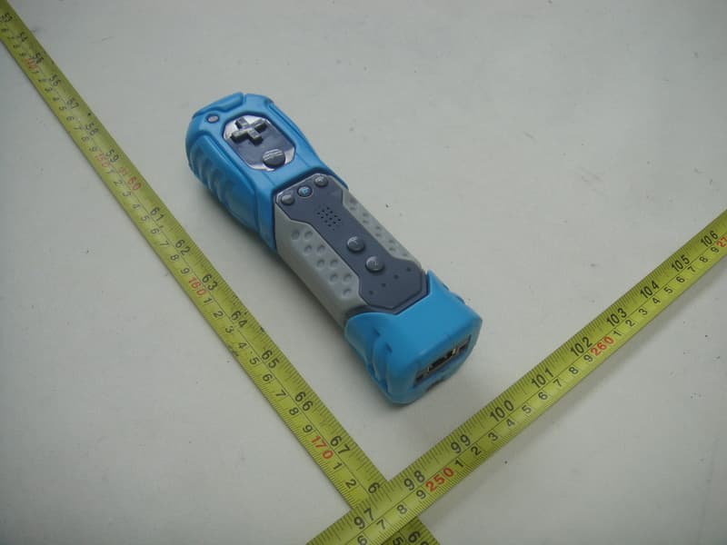
Click to zoom
Application Details
- Equipment Class
- DSS - Part 15 Spread Spectrum Transmitter
- Date of Grant
- Nov 07, 2010
- Application Purpose
- Original Equipment
- Date of Application
- Nov 04, 2010
- Equipment Note
- NERF REMOTE FOR Wii
- Frequency Range
- 2402.00000000 - 2480.00000000
- Country
- United States
Documents & Files
Document Text
Text extracted from the exhibit documents filed with the FCC. Open a document above to read the original.
Users Manual
NERF REMOTE FOR Wii Users’ Manual Setup of the NerF Remote for Wii 1) Push the tab on the battery door and lift to open. Place 2AA baterries (not inlcuded) in the battery compartment. Be sure to follow the + and – directions for proper battery insertion. PDP recommends new, high quality alkaline batteries for best performance. 2) Press the power button on the Wii console to turn it on. 3) Press and release the red SYNC button on the NERF Remote located inside the battery compartment. The Player LEDs will flash on the front of the NERF Remote. 4) Open the SD Card Slot cover on the front of the Wii Console. Press and release the red SYNC button on the Wii console. 5) When the NERF Remote player lights stop flashing, the NERF Remote will be synced. The light that is illuminated will indicate the player position. 6) Close the SD Card Slot cover on the Wii console and replace the battery door on the NERF Remote. 7) Thread the wrist strap (included) through the holes on the bottom back side of the NERF Remote and knot it by leading the wrist strap through the loop and pulling tightly. 8) Place your hand through the wrist strap and slide the strap lock up so that the strap will not fall off your wrist. Power Save Mode: Controller will go into Power Save Mode after 3 (three) minutes of inactivity. You need to press the START button to turn it back to the ACTIVE mode Important Notice 1. Do not place different types or capacities of battery together. 2. Recommended user age range 12+. 3. Adult supervision is necessary when controller is used by child CAUTION: Changes or modifications to this equipment not expressly approved by the manufacturer could void the users authority to operate the equipment. This equipment has been tested and found to comply with the limits for a Class B digital device, pursuant to part 15 of the FCC Rules. These limits are designed to provide reasonable protection against harmful interference in a residential installation. This equipment generates, uses and can radiate radio frequency energy and, if not installed and used in accordance with the instructions, may cause harmful interference to radio communications. However, there is no guarantee that interference will not occur in a particular installation. If this equipment does cause harmful interference to radio or television reception, which can be determined by turning the equipment off and on, the user is encouraged to try to correct the interference by one or more of the following measures:
External Photos
Neutron Engineering Inc. Project No.: 1009C135 Page 2 of 9 1009C135 1009C135 Neutron Engineering Inc. Project No.: 1009C135 Page 2 of 9 1009C135 1009C135 Neutron Engineering Inc. Project No.: 1009C135 Page 3 of 9 1009C135 1009C135 Neutron Engineering Inc. Project No.: 1009C135 Page 3 of 9 1009C135 1009C135
Internal Photos
Neutron Engineering Inc. Project No.: 1009C135 Page 4 of 9 1009C135 1009C135 Neutron Engineering Inc. Project No.: 1009C135 Page 4 of 9 1009C135 1009C135 Neutron Engineering Inc. Project No.: 1009C135 Page 5 of 9 1009C135 Neutron Engineering Inc. Project No.: 1009C135 Page 6 of 9 1009C135 1009C135 Neutron Engineering Inc. Project No.: 1009C135 Page 6 of 9 1009C135 1009C135 Neutron Engineering Inc. Project No.: 1009C135 Page 7 of 9 1009C135 1009C135 Neutron Engineering Inc. Project No.: 1009C135 Page 7 of 9 1009C135 1009C135 Neutron Engineering Inc. Project No.: 1009C135 Page 8 of 9 1009C135 1009C135 Neutron Engineering Inc. Project No.: 1009C135 Page 8 of 9 1009C135 1009C135 Neutron Engineering Inc. Project No.: 1009C135 Page 9 of 9 1009C135
RF Exposure Info
Neutron Engineering Inc. FCC RF EXPOSURE REPORT FCC ID: X5B-PL7672 Project No. : 1009C135 Equipment : NERF REMOTE FOR Wii Model : PL-7672 Applicant : Performance Designed Products, LLC Address : 14144 Ventura Blvd. Suite 200 Sherman Oaks, CA 91423 According: : FCC Guidelines for Human Exposure IEEE C95.1 Neutron Engineering Inc. No.3, Jinshagang 1st Road, ShiXia, Dalang Town, Dong Guan, China. TEL : (0769) 8318-3000 FAX : (0769) 8319-6000 Neutron Engineering Inc. GENERAL CONCULUSION: No evaluation required if power is below this threshold: F(GHz) P(mW) Low 2.402 High 2.480 24.620 Maximum measured transmitter power: Out Power (dBm) Out Power (mW) Conducted Power-6.43 0.228 EIRP Power -4.92 0.322 Note: Table for Filed Antenna (2T3R) Ant . Brand Model Name Antenna Type Connector Gain (dBi) NOTE - - PIFA N/A 1.51 BT Antenna Threshold for no SAR evaluation is 24.620mW. Transmitter power is 0.322 mW. Conclusion: No SAR evaluation required since transmitter power is below FCC threshold
Test Report
Neutron Engineering Inc. Report No.: NEI-FCCP-1-1009C135 Page 2 of 65 Declaration Neutron represents to the client that testing is done in accordance with standard procedu res as applicable and that test instruments used has been calibrated with the standards traceable to National Measurement Laboratory (NML) of R.O.C., or National Institute of Standards and Technology (NIST) of U.S.A. Neutron's reports apply only to the specific samples tested under conditions. It is manufacture’s responsibility to ensure that additional production units of this model are manufactured with the identical electrical and mechanical components. Neutron shall have no liability for any declarations, inferences or generalizations drawn by the client or others from Neutron issued reports. Neutron’s reports must not be used by the client to claim product endorsement by the authorities or any agency of the Government. This report is the confidential property of the client. As a mutual protection to the clients, the public and Neutron-self, extracts from the test report shall not be reproduced except in full with Neutron’s authorized written approval. Neutron’s laboratory quality assurance procedures are in compliance with the ISO Guide 17025 requirements, and accredited by the conformity assessment authorities listed in this test report. Limitation For the use of the authority's logo is limited unless the Test Standard(s)/Scope(s)/Item(s) mentioned in this test report is (are) included in the conformity assessment authorities acceptance respective. Neutron Engineering Inc. Report No.: NEI-FCCP-1-1009C135 Page 3 of 65 Table of Contents Page 1 . CERTIFICATION 6 2 . SUMMARY OF TEST RESULTS 7 2.1 TEST FACILITY 8 2.2 MEASUREMENT UNCERTAINTY 8 3 . GENERAL INFORMATION 9 3.1 GENERAL DESCRIPTION OF EUT 9 3.2 DESCRIPTION OF TEST MODES 11 3.3 TABLE OF PARAMETERS OF TEXT SOFTWARE SETTING 11 3.4 BLOCK DIGRAM SHOWING THE CONFIGURATION OF SYSTEM TESTED 12 3.5 DESCRIPTION OF SUPPORT UNITS(CONDUCTED MODE) 13 4 . EMC EMISSION TEST 14 4.1 CONDUCTED EMISSION MEASUREMENT 14 4.1.1 POWER LINE CONDUCTED EMISSION LIMITS 14 4.1.2 MEASUREMENT INSTRUMENTS LIST AND SETTING 14 4.1.3 TEST PROCEDURE 15 4.1.4 DEVIATION FROM TEST STANDARD 15 4.1.5 TEST SETUP 15 4.1.6 EUT OPERATING CONDITIONS 16 4.1.7 TEST RESULTS 17 4.2 RADIATED EMISSION MEASUREMENT 18 4.2.1 RADIATED EMISSION LIMITS 18 4.2.2 MEASUREMENT INSTRUMENTS LIST ANS SETTING 19 4.2.3 TEST PROCEDURE 20 4.2.4 DEVIATION FROM TEST STANDARD 20 4.2.5 TEST SETUP 21 4.2.6 EUT OPERATING CONDITIONS 21 4.2.7 TEST RESULTS (BETWEEN30 – 1000 MHZ) 22 4.2.8 TEST RESULTS (ABOVE 1000 MHZ) 24 5 . NUMBER OF HOPPING CHANNEL 36 5.1 APPLIED PROCEDURES / LIMIT 36 5.1.1 MEASUREMENT INSTRUMENTS LIST AND SETTING 36 5.1.2 TEST PROCEDURE 36 5.1.3 DEVIATION FROM STANDARD 36 5.1.4 TEST SETUP 36 5.1.5 EUT OPERATION CONDITIONS 36 5.1.6 TEST RESULTS 37 Neutron Engineering Inc. Report No.: NEI-FCCP-1-1009C135 Page 4 of 65 Table of Contents Page 6 . AVERAGE TIME OF OCCUPANCY 38 6.1 APPLIED PROCEDURES / LIMIT 38 6.1.1 MEASUREMENT INSTRUMENTS LIST 38 6.1.2 TEST PROCEDURE 38 6.1.3 DEVIATION FROM STANDARD 38 6.1.4 TEST SETUP 39 6.1.5 EUT OPERATION CONDITIONS 39 6.1.6 TEST RESULTS 40 7 . HOPPING CHANNEL SEPARATION MEASUREMENT 46 7.1 APPLIED PROCEDURES / LIMIT 46 7.1.1 MEASUREMENT INSTRUMENTS LIST AND SETTING 46 7.1.2 TEST PROCEDURE 46 7.1.3 DEVIATION FROM STANDARD 46 7.1.4 TEST SETUP 46 7.1.5 EUT OPERATION CONDITIONS 46 7.1.6 TEST RESULTS 47 8 . BANDWIDTH TEST 49 8.1 APPLIED PROCEDURES / LIMIT 49 8.1.1 MEASUREMENT INSTRUMENTS LIST AND SETTING 49 8.1.2 TEST PROCEDURE 49 8.1.3 DEVIATION FROM STANDARD 49 8.1.4 TEST SETUP 49 8.1.5 EUT OPERATION CONDITIONS 49 8.1.6 TEST RESULTS 50 9 . PEAK OUTPUT POWER TEST 52 9.1 APPLIED PROCEDURES / LIMIT 52 9.1.1 MEASUREMENT INSTRUMENTS LIST AND SETTING 52 9.1.2 TEST PROCEDURE 52 9.1.3 DEVIATION FROM STANDARD 52 9.1.4 TEST SETUP 52 9.1.5 EUT OPERATION CONDITIONS 52 9.1.6 TEST RESULTS 53 10 . ANTENNA CONDUCTED SPURIOUS EMISSION 55 10.1 APPLIED PROCEDURES / LIMIT 55 10.1.1 MEASUREMENT INSTRUMENTS LIST AND SETTING 55 10.1.2 TEST PROCEDURE 55 10.1.3 DEVIATION FROM STANDARD 55 10.1.4 TEST SETUP 55 10.1.5 EUT OPERATION CONDITIONS 55 Neutron Engineering Inc. Report No.: NEI-FCCP-1-1009C135 Page 5 of 65 Table of Contents Page 10.1.6 TEST RESULTS 56 11 . RF EXPOSURE TEST 62 11.1 APPLIED PROCEDURES / LIMIT 62 11.1.1 MEASUREMENT INSTRUMENTS LIST 62 11.1.2 MPE CALCULATION METHOD 63 11.1.3 DEVIATION FROM STANDARD 63 11.1.4 TEST SETUP 63 11.1.5 EUT OPERATION CONDITIONS 63 11.1.6 TEST RESULTS 64 12 . EUT TEST PHOTO 65 Neutron Engineering Inc. Report No.: NEI-FCCP-1-1009C135 Page 6 of 65 1. CERTIFICATION Equipment : NERF REMOTE FOR Wii Brand Name : NERF Model Name : PL-7672 Applicant : Performance Designed Products,LLC Date of Test: Sep. 16, 2010 ~ Oct. 29, 2010 Test Item : ENGINEERING SAMPLE Standards : FCC Part15, Subpart C(15.247) / ANSI C63.4 : 2003 The above equipment has been tested and found compliance with the requirement of the relative standards by Neutron Engineering Inc. EMC Laboratory. The test data, dat a evaluation, and equipment configuration contained in our test report (Ref No. NEI-FCCP-1-1009C135) were obtained utilizing the test procedures, test instruments, test sites that has been accredited by the Authority of NVLAP and TAF according to the ISO-17025 quality assessment standard and technical standard(s). Neutron Engineering Inc. Report No.: NEI-FCCP-1-1009C135 Page 7 of 65 2. SUMMARY OF TEST RESULTS Test procedures according to the technical standards: FCC Part15 (15.247) , Subpart C Standard Section Test Item Judgment Remark 15.207 Conducted Emission N/A 15.247(d) Antenna conducted Spurious Emission PASS 15.247 (a)(1) Hopping Channel Separation PASS 15.247 (b)(1) Peak Output Power PASS 15.247(d)/15.209 Radiated Spurious Emission PASS 15.247 (a)(1)(iii) Number of Hopping Frequency PASS 15.247 (a)(1)(iii) Dwell Time PASS 15.205 Restricted Bands PASS 15.203 Antenna Requirement PASS 1.1307 1.13…
Text truncated - open the document above for the full version.
Test Setup Photos
Neutron Engineering Inc. Report No.: NEI-FCCP-1-1009C135 Page 65 of 65 12. EUT TEST PHOTO Radiated Measurement Photos Neutron Engineering Inc. Report No.: NEI-FCCP-1-1009C135 Page 65 of 65 12. EUT TEST PHOTO Radiated Measurement Photos
Contact Information
Applicant
Tom Roberts(Chief Technical Officer)
Technical Contact
Neutron Engineering, Inc.Steven Lu
No.3 Jinshagang 1st Rd, Shixia, Dalang · Dongguan City · China
Test Firm
BTL Inc.Daisy Dai
Technical Specifications
| # | Rule Parts | Frequency Range | Power Output |
|---|---|---|---|
| 1 | 15C | 2.40 GHz - 2.48 GHz | 228.00 µW |
Other Applications from Performance Designed Products, LLC
X5B-049037X
Aug 22, 2024PDP REALMz Wireless Controller for Xbox
Equipment Class
DTS - Digital Transmission SystemX5B-049037T
Aug 22, 2024PDP REALMz Wireless Dongle for Xbox
Equipment Class
DTS - Digital Transmission SystemX5B-500253
Aug 02, 2024Rematch Wireless Controller for Nintendo Switch
Equipment Class
DSS - Part 15 Spread Spectrum TransmitterX5B-500246
Aug 01, 2024Wireless Controller for Nintendo Switch
Equipment Class
DSS - Part 15 Spread Spectrum TransmitterX5B-049038X
Jun 28, 2024Phantom Air Wireless Headset for Xbox / Phantom Air Wireless Headset for Play Station
Equipment Class
DSS - Part 15 Spread Spectrum Transmitter