X5SROOK-RF-508Wireless flash trigger
Pixel Enterprise Limited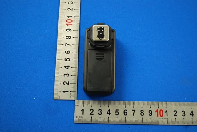
Click to zoom
Application Details
- Equipment Class
- DXX - Part 15 Low Power Communication Device Transmitter
- Date of Grant
- May 12, 2013
- Application Purpose
- Original Equipment
- Date of Application
- May 12, 2013
- Equipment Note
- Wireless flash trigger
- Frequency Range
- 2406.52000000 - 2445.00000000
- Company
- Pixel Enterprise Limited
- Country
- Hong Kong
Documents & Files
Document Text
Text extracted from the exhibit documents filed with the FCC. Open a document above to read the original.
Users Manual
Thank you so much for purchasing PIXEL product, ROOK is a professional grouping flash trigger. TTL mode available on transmitter h ot shoe and sync with off shoe trigger together. Off shoe trigger can be grouped the fla sh and Remote the camera. ROOK is using global free FSK 2.4 GHz which is more stabilize . 1、 Make sure the camera is powered off before install device. 2、 This is electronic products accessories ; some of the environment causes may affect the working . However this is hardly ever to get this situation , don ' t worry ! 3、 This component can't be strong vibration, or may lead to prod uct failure. 4、 For a long time non-use, please turned off the transmitter an d the receiver's power and remove the battery. 5、 The batteries should not install anti-polarity ; otherwise the batteries may leak . corrosive liquids, heat or explosion. 6、 When the product connected to the device, Do not pull the wire s. 7、 Do not put it in high temperature, such as a closed car under di rect sunlight, the control panel and other high - temperature areas . 8、 keep dry, do not use wet hand contact with the product, the pro duct must not be immersed in water or exposed to rain, and this may lead to not work properly. 9、 Do not use flammable gases in violation of this warning may ca use an explosion or fire. 、 10 Because of this product is included battery ; please strictly follow the instruction for operation . Otherwise its may cause an explosion, fire or personal injur y. Overview 1 R OOK is a professional grouping flash trigger . 2 Transmitter hot shoe support TTL and sync with off shoe flash . 3 Wake-up function available, the flash will be wake up automatically. 4 Through studio light to connect PC or USB socket, the sync speed up to 1/320s ( Sync time may have little bit inacurracy as difference camera model ) 5 Available to control the shooting or through master camera to control slave camera. 、、、、 、 3 Receiver Professional Flash TriggerInstruction ManualROOK 1 Power/group switch Chanel setting Indicator Light Battery compartment 1 1 2 2 3 3 4 5 7 6 7 Output socket 4 5 6 ee ss s i o n a l Fl F l aa s h Trh Trh Tr i g g e rr O K Sony series camera, Minolta series camera ROOK Model compatible list as below : Transmitter ( TX ) Receiver ( RX ) Canon series camera Nikon series camera, Samsung series camera Fujifilm series camera, Pantex series camera Compatible 2 1 2 3 4 5 7 6 8 Trigger point Group Indicate Light Chanel settingPower/group setting Battery compartment 1 2 3 4 5 7 6 8 Input/outputsocket Transmitter Hot shoe protector Included Items Specification 4 Battery Installation: Set transmitter and receiver to the same channel 5 AAA + - AAA + - Please locate the battery accordingto the icon in the battery compartment . Channel Setting: Set transmitter and receiver to thesame channel1.Slide the switch to change channel.2. Channel changing as: CH1 → CH2 → CH3 → CH4 ( as figure ) CH 1 CH 4 CH 2 CH 3 For a long time non-use, please turned off the transmitter and the receiver 's power and remove the battery. * Transmitter and receiver must be set as the same channel . * A 、 B 、 C LED light on means the current setting will be working with transmitter. 4. No action within 2 seconds, the group LED light will off. * Receiver only get signal from transmitter when the current group setting of receiver is included in the validate group of transmitter. Testing:1. Check power on or off. 2. Check the frequency of transmitter and receiver. 3. Check the group setting of transmitter and receiver. 6 Group setting:Group setting on transmitter 1.wake up group display, and show the current controlling group. Slightly press [ ] to show group mode which showing the current working group. 2. Press again [ ] to change group . 3. Group changin g a s : CH 1 CH 1 CH 1 CH 3 Group setting on receiver Put Power/group switch at A/B/C, and then turn on the receivers. 3.Trigger the Flash.1.Insert flashgun on the receiver and turn on the flash power; set the flash index as minimum. 2.Full press the test button 1. Tight the Hot shoe with screw, and then turn right to release. 2. Plug the transmitter on the camera hot shoe. 3. Tight the Hot shoe with screw, and then turn left to lock. Connect the transmitter to camera hot shoe 1. Plug PC-3.5 connecting cable to transmitter 3.5mm socket. 2 . Plug PC-3.5 connecting cable to camera PC socket. Connect transmitter to camera via PC-3.5 connecting cable. 7 How to connect the relative photo equipment Testing the receiver signal as below: (2 (1 1. Split the protecting film on the receiver holder and stick it on the studio light as figure. 2. Mount the receiver on the receiver holder. 3. Use 3.5-3.5 or 3.5-1/2 according to studio light socket. 4. Plug 3.5mm side into the transmitter input. 5. Insert another side into the studio light socket. Connect the Receiver to Studio Light 2 3 1 1. Unlock the Speedlite Flash locking screw. 2. Inser t the Speedlite Flash into the receiver hot shoe as figure.3. According to the flash locking method to lock the speedlite on receiver. Connect the Receiver to Speedlite Flash 1.Plug shutter connecting cable ( 3.5mm side) into the receiver socket . 2.Plug shutter connecting cable ( camera side ) into the camera shutter release socket . Connect Receiver to Camera 8 (1 (2 Cautions before use Receiver holder for Canon for Nikon for Sony for Olympus/ Panasonic For Sony for Olympus/ Panasonic For Nikon For Canon Model Above brand name is registered by the respective owner. Qriginal speedlite, studio light,Metz, SUNPAK,Sigma Olympus/Panasonic series camera Feature Prepare to use *PC-3.5 connecting cable should be purchased separately. ( ) Transmitter Transmitter Receiver Transmitter Receiver *The shutter cable should be purchased separately . Wireless Frequency System: Operating Distance: Shutter Sync Speed: 1/200S Group setting: 3 difference group (7 combinations) Wireless Channel: 4 Stand-by Time 250 hours : : Transmitter : 5 years Power : AAA x2 Weight: Transm…
Text truncated - open the document above for the full version.
Users Manual
Speedlite flash TTL + Speedlite flash trigger remote control By using of the TTL off-camera cable to trigger the off-camera flash when the Speedlite TTL flash works. 9 10 11 12 Speedlite flash TTL + Speedlite flash trigger remote control OFF ON 13 14 16 Transmitter Control shooting * Some Cameras won ' t shoot if the camera cannot focus even get shooting signal, so please adjust the camera to “ MF ” Slightly press the transmitter button . Non-compatible mode using method is same as compatible mode . 15 1. Slightly half-press release button, transmitter and receiver indicate light as Green, then the camera starting focus . 2. Fully press release button, transmitter and receiver as Red , then the camera starting shoot . OFF ONOFF ONOFF ONOFF ONOFF ONOFF ONOFF ONOFF ONOFF ONOFF ONOFF ONOFF ONOFF ONOFF ONOFF ONOFF ON , t r a n s m i t t e r n , t h e n t h e i t t e r e r a Speedlite flash TTL + off-camera flash trigger remote contr ol The transmitter supports the Speedlite flash and will not hamper TTL communication of camera. Furthermore, it will send the sync signal and trigger the off-camera flashgun meanwhile. Speedlite flash TTL + Studio light off-camera flash trigger r emote control Speedlite flash TTL + Speedlite flash trigger remote control Studio light off-camera flash trigger remote control Speedlite flash trigger remote control Use under incompatible mode When the transmitter is incompatible with the camera, you should use it as below: Remote control Master camera control the slave camera Camera on top TTL, PC off-camera sync trigger. Off-camera flash remote controlTransmitter installed on camera hot shoe, and trigger the flash light. Figure Explaination Flash grouping remote control Half - press the camera shooting button , master camera and all slave cameras starting focus . Fully - press the camera shooting button and all the cameras starting shoot. Now you can start to use incredible PIXEL product . If you have any question , you can contact the local dealer or visit to http://www.pixelhk.com . This manual information is updated at May 1 , 20 11. If you want to use this product combined with others , which published after this date ; please consult with the PIXEL dealer for further information. *As camera has difference reaction time, then shooting time will be little difference.*Some Cameras won ' t shoot if the camera cannot focus even get shooting signal, so please adjust the camera to “ MF ” *The camera cannot focus if the transmitter is not specific for the camera. *The shutter cable should be purchased separately. Speedlite flash TTL + Studio light off-camera flash trigger r emote control dddddddddddd lllllllll iiiiiiiiiiiiiiiii t e f l h T T L + L + L + L + L + L + L + L + L + L + L + L + L + L + L + L + L + L + L + L + L + L + L + L + L + SSSSSSSSSSSSSSSSSSSSSSSSSSSSS d l i Speedlite flash TTL + Speedlite flash trigger remote control Receiver A 、 B 、 C will operate when transmitter set at A B C. Receiver A B will operate when transmitter set at A B. Receiver B will operate when transmitter set at B. Receiver A will operate when transmitter set at A. 261121 V 10.01 Slave Camera Master Camera Receiver *Camera Shutter cable is purchased separately . Transmitter Input / output trigger off - camera flash and output flash . Transmitter Speedlite TTL , Input / Output synchronous Trigger, off-camera light synchronous Trigger *If the shooting interval time or 2 shooting times is longer than 30s, you need to press button again, or it may miss flash . changes or modifications not expressly approved by the party responsi ble for compliance could void the user's authority to operate the equipment. This device complies with Part 15 of the FCC Rules. Operation is subject to the f ollowing two conditions: (1) this device may not cause harmful interference, and (2) this device must accep t any interference received, including interference that may cause undesired operation. This equipment has been tested and found to comply with the limits for a Class B di gital device, pursuant to Part 15 of the FCC Rules. These limits are designed to provide reasonable prote ction against harmful interference in a residential installation. This equipment generates, uses and ca n radiate radio frequency energy and, if not installed and used in accordance with the instructions, may cause harmf ul interference to radio communications. However, there is no guarantee that interference wil l not occur in a particular installation. If this equipment does cause harmful interference to radio or televisio n reception, which can be determined by turning the equipment off and on, the user is encouraged to try to correct the in terference by one or more of the following measures: -- Reorient or relocate the receiving antenna. -- Increase the separation between the equipment and receiver. -- Connect the equipment into an outlet on a circuit different from that to whi ch the receiver is connected. -- Consult the dealer or an experienced radio/TV technician for help.
External Photos
1 Photographs - EUT Constructional Details (Test Model No.:RF-508)
ID Label/Location Info
FCC ID: X5SROOK-RF-508
Internal Photos
1 Photographs - EUT Constructional Details (Test Model No.:RF-508)
Test Report
SGS-CSTC Standards Technical Services Ltd. No. 1 W orkshop, M-10, Middle section, Science & Technology Park, Nanshan District, Shenzhen, Guangdong, China 518057 Telephone: +86 (0) 755 2601 2053 Fax: +86 (0) 755 2671 0594 Email: [email protected] Report No.: SZEM130300119801 Page: 1 of 25 Authorized Signature: Jack Zhang EMC Laboratory Manager The manufacturer should ensure that all products in series production are in conformity with the product sample detailed in this report. If the product in this report is used in any configuration other than that detailed in the report, the manufacturer must ensure the new system complies with all relevant standards. Any mention of SGS International Electrical Approvals or testing done by SGS International Electrical Approvals in connection with, distribution or use of the product described in this report must be approved by SGS International Electrical Approvals in writing. The report must not be used by the client to claim product certification, approval, or endorsement by NVLAP, NIST, or any agency of the federal government. All test results in this report can be traceable to National or International Standards. “This document is issued by the Company subject to its General Conditions of Service printed overleaf, available on request or accessible at www.sgs.com/terms_and_conditions.htm and, for electronic format documents, subject to Terms and Conditions for Electronic Documents at www.sgs.com/terms_e-document.htm . Attention is drawn to the limitation of liability, indemnification and jurisdiction issues defined therein. Any holder of this document is advised that information contained hereon reflects the Company’s findings at the time of its intervention only and within the limits of Client’s instructions, if any. The Company’s sole responsibility is to its Client and this document does not exonerate parties to a transaction from exercising all their rights and obligations under the transaction documents. This document cannot be reproduced except in full, without prior written approval of the Company. Any unauthorized alteration, forgery or falsification of the content or appearance of this document is unlawful and offenders may be prosecuted to the fullest extent of the law. Unless otherwise stated the results shown in this test report refer only to the sample(s) tested and such sample(s) are retained for 90 days only. 1 Cover page FCC REPORT Application No. : SZEM1303001198RF Applicant: Pixel Enterprise Limited Product Name: ROOK Model No.(EUT): RF-508 FCC ID: X5SROOK-RF-508 Standards: 47 CFR Part 15, Subpart C (2012) Date of Receipt: 2013-03-19 Date of Test: 2013-04-19 to 2013-04-25 Date of Issue: 2013-05-10 Test Result: PASS * * In the configuration tested, the EUT complied with the standards specified above. SGS-CSTC Standards Technical Services Ltd. Report No.: SZEM130300119801 Page : 2 of 25 “This document is issued by the Company subject to its General Conditions of Service printed overleaf, available on request or accessible at www.sgs.com/terms_and_conditions.htm and, for electronic format documents, subject to Terms and Conditions for Electronic Documents at www.sgs.com/terms_e-document.htm . Attention is drawn to the limitation of liability, indemnification and jurisdiction issues defined therein. Any holder of this document is advised that information contained hereon reflects the Company’s findings at the time of its intervention only and within the limits of Client’s instructions, if any. The Company’s sole responsibility is to its Client and this document does not exonerate parties to a transaction from exercising all their rights and obligations under the transaction documents. This document cannot be reproduced except in full, without prior written approval of the Company. Any unauthorized alteration, forgery or falsification of the content or appearance of this document is unlawful and offenders may be prosecuted to the fullest extent of the law. Unless otherwise stated the results shown in this test report refer only to the sample(s) tested and such sample(s) are retained for 90 days only.” 2 Test Summary Test Item Test Requirement Test method Result Antenna Requirement 47 CFR Part 15, Subpart C Section 15.203 ANSI C63.10 (2009) PASS AC Power Line Conducted Emission 47 CFR Part 15, Subpart C Section 15.207 ANSI C63.10 (2009) N/A Field Strength of the Fundamental Signal 47 CFR Part 15, Subpart C Section 15.249 (a) ANSI C63.10 (2009) PASS Spurious Emissions 47 CFR Part 15, Subpart C Section 15.249 (a)/15.209 ANSI C63.10 (2009) PASS Band Edge (Radiated Emission) 47 CFR Part 15, Subpart C Section 15.249(a)/15.205 ANSI C63.10 (2009) PASS 20dB Occupied Bandwidth 47 CFR Part 15, Subpart C Section 15.215 (c) ANSI C63.10 (2009) PASS Remark: N/A: In this while report not applicable Note: Due to the EUT is powered by the battery only, the AC Power Line Conducted Emission is not applicable. SGS-CSTC Standards Technical Services Ltd. Report No.: SZEM130300119801 Page : 3 of 25 “This document is issued by the Company subject to its General Conditions of Service printed overleaf, available on request or accessible at www.sgs.com/terms_and_conditions.htm and, for electronic format documents, subject to Terms and Conditions for Electronic Documents at www.sgs.com/terms_e-document.htm . Attention is drawn to the limitation of liability, indemnification and jurisdiction issues defined therein. Any holder of this document is advised that information contained hereon reflects the Company’s findings at the time of its intervention only and within the limits of Client’s instructions, if any. The Company’s sole responsibility is to its Client and this document does not exonerate parties to a transaction from exercising all their rights and obligations under the transaction documents. This document cannot be reproduced except in full, without prior written approval of the Company. Any unauthorized alteration, forgery or falsification of the conten…
Text truncated - open the document above for the full version.
Contact Information
Applicant
Weikun Chen(General manager)
Test Firm
SGS-CSTC Standards Technical Services Co.,Ltd.June Zhang
Technical Specifications
| # | Rule Parts | Frequency Range | Power Output |
|---|---|---|---|
| 1 | 15C | 2.41 GHz - 2.44 GHz | - |
Other Applications from Pixel Enterprise Limited
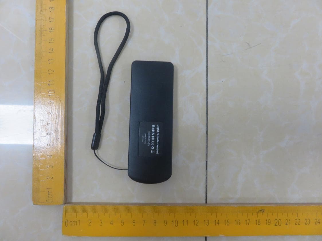
X5S-C220
Jan 07, 2020Photographic light
Equipment Class
DXX - Part 15 Low Power Communication Device Transmitter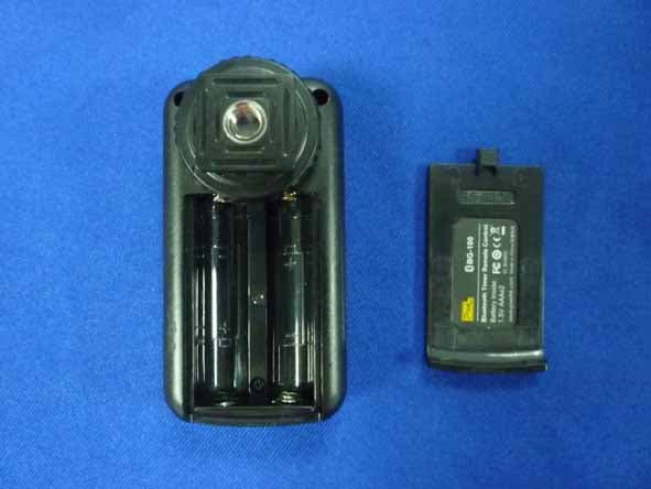
X5SBG-100
Jun 07, 2014Bluetooth Timer Remote Control
Equipment Class
DTS - Digital Transmission System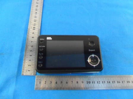
X5SEXPERT-402RX
Feb 19, 2012Expert
Equipment Class
DXX - Part 15 Low Power Communication Device Transmitter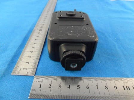
X5SEXPERT-402TX
Feb 19, 2012Expert
Equipment Class
DXX - Part 15 Low Power Communication Device Transmitter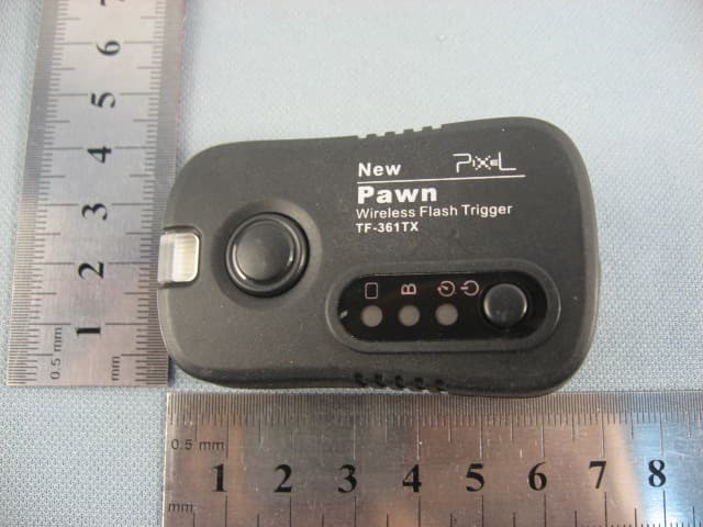
X5SPAWNSOLDIER-TX
Apr 17, 2011Pawn and Soldier
Equipment Class
DXX - Part 15 Low Power Communication Device Transmitter