X78XLK1LCD Keypad
Guardall, a division of CSG Security Corp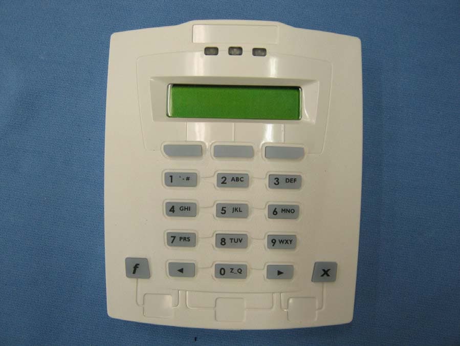
Click to zoom
Application Details
- Equipment Class
- DCD - Part 15 Low Power Transmitter Below 1705 kHz
- Date of Grant
- Sep 22, 2010
- Application Purpose
- Original Equipment
- Date of Application
- Sep 22, 2010
- Equipment Note
- LCD Keypad
- Frequency Range
- 0.12400000 - 0.12600000
- Country
- Canada
Documents & Files
Document Text
Text extracted from the exhibit documents filed with the FCC. Open a document above to read the original.
Users Manual
21-3618v1.1 MONITOR ISM™ / AFx™ Suite Security 4 Zone Keypad Installation CSG Security Corp. / Sécurité CSG Corp. Page 1 of 4 Guardall 5201 Explorer Drive, Mississauga, Ont., Canada. L4W-4H1 [email protected] +1 905.206.8434 | [email protected] +1 905.206.8436 | Fax: +1 905.629.4970 www.guardall.com | +1 877.249.9993 These instructions describe the hardware installation of the MONITOR ISM/AFx 4 Zone Suite Security Keypad. This keypad can only be configured through the Monitor ISM/AFx Director Software in “Suite Security” programming (software and main panel firmware version 4.58E or greater is required). For details, refer to the Director software on-line help or latest Monitor ISM/AFx Director Software User’s Guide. For 4 zone keypad command entries, keypad tones and light display descriptions, please refer to the Multi-Tenant Apartment Security System User Guide, P/N 21-3615. System Overview The 4 zone keypad provides suite security for a wide range of applications from a simple strip plaza to a multi-tower residential apartment. When using suite security keypads only, each main control panel can support a maximum of 60 keypads. ! ! Do's & Don’ts ! ! • Static can destroy IC chips! Always take proper precautions when handling or transporting circuit boards. • Remove all power (AC and back-up battery) before servicing this unit. • Always conform to local fire and building regulations (if unsure, find out). • Refer to the system commissioning guide, and follow the details therein regarding: + General installation guidelines; + Upgrading an existing system; + Standards and emissions issues; + Input-point circuit-wiring reference; + Setting up a new system. • Then, be sure to follow the details in this document, pertaining to: Page + System Overview................................1 + System grounding requirements ........2 + Mounting details .................................2 + Wiring reference ................................2 + Power and Cable requirements .........3 + Keypad Service Commands ...............3 + Specifications .....................................4 cde Typical Steps cde 1) Read "Do's & Don’ts" above, & ensure all installation instructions are present. 2) Unpack and check all items. (Ensure you have all necessary items including: Director software, main panel, all modules and peripherals, sensors, all cabling, and all related documentation). 3) Plan device and sensor locations, and run all cables as required. To prevent damage, run cables before mounting the specific modules. 4) Install sensors in desired locations. Be sure to distance all cables from sources of electromagnetic interference (arc welders, motors, ballasts, etc.). 5) Mount these units and supplementary power supplies (see Power Requirements, page 3). 6) Complete the wiring. Refer to the illustration(s) that follow, in addition to the input-point circuit details in the system-commissioning guide. 7) Power up and test as necessary. 8) Install other modules, peripherals, etc. Refer to the instructions for each item. Tip: Record five digit serial numbers on each keypad to program into the system during Suite Security programming. 9) Install your software and set up the system. Refer to the on-line help or user's guide provided with your system software, or the commissioning reference guide for your system. 10) When finished, ensure all wires are clear, and secure the cover (or door). 11) Hand over to the customer, answer questions and perform training and tests as necessary. System Grounding Cabinet Grounding: Each metal cabinet in the system must be connected to a locally- approved earth ground, using at least 18 AWG (stranded) cable. Cable Shield Grounding: The module bus cable shield is to be earth-grounded only at the main panel, and connected together at each module. Module Logical Grounding: The module bus ( – ) connection provides a common ground reference for all controller modules. Do not connect this to the cabinet earth ground. Power Supply Grounding: For any supplementary power supplies, the 0V / Ref. Gnd. line must NOT be earth grounded. Warning Changes or Modifications not expressly approved by the manufacturer could void the user's authority to operate this equipment. 21-3618v1.1 MONITOR ISM™ / AFx™ Suite Security 4 Zone Keypad Installation CSG Security Corp. / Sécurité CSG Corp. Page 2 of 4 Guardall 5201 Explorer Drive, Mississauga, Ont., Canada. L4W-4H1 [email protected] +1 905.206.8434 | [email protected] +1 905.206.8436 | Fax: +1 905.629.4970 www.guardall.com | +1 877.249.9993 Mounting and Wiring Reference: 1 , - # 2 ABC 3 DEF 45 JKL 6 MNOGHI 78 TUV 9 WXYPRS Keypad LEDs Red Flashing: Protection ON Solid: Partial protection (STAY) Green On Solid with power present. Yellow On Solid when points not normal or when point in tamper. Red Green Yellow 15:25 18Sep OOO Pin:----- 0 Z_Q X X To use the keypad tamper spring as a wall tamper break out this plastic cylinder inside the back cover. Screw it to the wall, keeping it in the same hole as it was attached, so the back cover fits over it. The plastic cylinder prevents the spring from being affected by flat objects wedged in behind the keypad. The additional keypad base is optional. For installations using it there is a similar, shorter, washer style, plastic break out. Place it behind the plastic cylinder and screw them down together. Then place the holes in the base and keypad backing over top of them. Fit the spring inside the plastic cylinder part and secure the keypad front to the keypad back. The spring compressing should reset the keypad tamper condition. Knock outs for rectangular conduit using additional keypad base. K e y p a d B a c k K e y p a d F r o n t Circuit board pin connectors insert into fixed terminal blocks on inside of keypad back. This allows the keypad to make wire connections in the terminal blocks. Terminal Block T e r m i n a l B l o c k Tamper Spring Sonalert Cable After placing the keypad on its back section, make s…
Text truncated - open the document above for the full version.
Users Manual
21-3610 rev1.4 xL LCD Keypad Installation Instructions CSG SecurityCorp / Sécurité CSG Corp Page 1 of 2 GUARDALL 5201 Explorer Drive, Mississauga, Ont., Canada. L4W-4H1 sales@ guardall.com +1 905.206.8434 | support@ guardall.com +1 905.206.8436 | Fax: +1 905.629.4970 www.guardall.com | +1 877.249.9993 The LCD keypad provides the ability to operate the entire Monitor xL™ or Chubb AFx™ system. It will also provide readouts of the status of the systems and location and nature of alarms. 1 , - # 2 ABC 3 DEF 45 JKL 6 MNOGHI 78 TUV 9 WXYPRS Keypad LEDs Red Flashing: Protection ON Solid: Partial protection (STAY) Green On Always with power present. Yellow On when trouble condition present. Flashing when there is no AC mains. Red Green Yellow ComsLost#50624ef Enter code 42822 0 Z_Q X X To use the keypad tamper spring as a wall tamper break out this plastic cylinder inside the back cover. Screw it to the wall, keeping it in the same hole as it was attached, so the back cover fits over it. The plastic cylinder prevents the spring from being affected by flat objects wedged in behind the keypad. The additional keypad base is optional. For installations using it there is a similar, shorter, washer style, plastic break out. Place it behind the plastic cylinder and screw them down together. Then place the holes in the base and keypad backing over top of them. Fit the spring inside the plastic cylinder part and secure the keypad front to the keypad back. The spring compressing should reset the keypad tamper condition. Knock outs for rectangular conduit using additional keypad base. K e y p a d B a c k K e y p a d F r o n t Circuit board pin connectors insert into fixed terminal blocks on inside of keypad back. This allows the keypad to make wire connections in the terminal blocks. Terminal Block T e r m i n a l B l o c k Tamper Spring Sonalert Cable After placing the keypad on its back section, make sure the keypad's securing screws (supplied) are always I N ! Standard and G-ProxII 143256 PT1 0V PT2 PT3PT4 143256 A B0V OUT +12V 0V Wiegand 143256 D1D0 1 4 32 56 A B 0V OUT +12V 0V 0V PT1PT2 Keypad Terminal Block Wiring Module Bus Module Bus Output Input 1 Input 2 Common Wiegand Reader Data 1 and 0. No reader LED connection. Wall tamper knock out Flip Cover Serial # sticker for programming into Module Programming. Apply dealer's logo label (supplied) in the indented space at the top of the keypad. Apply the Alert Button labels as required. Alert Labels X X X X X Rectangular Conduit (Trunking) Keypad Output goes negative. Interface with a relay or power supply. Common their negatives with keypad 0V. Module Point Assignment: 8 points. First point: Fire Alert buttons Second point: Panic (Hold- Up) buttons Third point: Auxiliary Alert buttons Points 4 – 7 are hard wire inputs 1 – 4 on the Standard and G-ProxII version. Points 4 – 5 are hard wire inputs 1 – 2 on the Wiegand version. All unused points are skipped. Point 4 – 7 Point 4 – 5 Point 1 Point 2 Point 3 Ratings: LCD Keypad with Reader Input: 12 – 13.8VDC, 110mA Output: 12VDC, 1x10mA LCD Keypad Input: 12 – 13.8VDC, 95mA Output: 12VDC, 1x10mA Temp for both: -10°C to +55°C (14°F to 131°F) @ 93% Future Future 21-3610 rev1.4 xL LCD Keypad Installation Instructions CSG SecurityCorp / Sécurité CSG Corp Page 2 of 2 GUARDALL 5201 Explorer Drive, Mississauga, Ont., Canada. L4W-4H1 sales@ guardall.com +1 905.206.8434 | support@ guardall.com +1 905.206.8436 | Fax: +1 905.629.4970 www.guardall.com | +1 877.249.9993 3 Keypad Versions • LCD Keypad P/N 111-3610 (white), 111-3620 (gray): standard keypad includes 3 programmable alert button inputs, 4 hardwire alarm input points and 1 output point. • LCD Keypad with internal RF reader P/N 111-3611 (white), 111-3621(gray): keypad includes 3 programmable alert button inputs, 4 hardwire alarm input points and 1 output point. Includes a built-in RF G-Prox reader. • LCD with external Wiegand reader Keypad P/N 111-3612 (white), 111-3622 (gray): keypad includes the capability to connect an external Weigand reader to it. Keypad includes 3 programmable alert button inputs, 2 hardwire alarm input points and 1 output point. NOTE: – Double or triple card touch (badge) to LCD with external reader is the equivalent of hold a card (badge) feature at the LCD with internal reader to e.g. turn protection on and off. – GProxII and MIFARE readers have been proven to work acceptably when connected to the LCD with external reader. All versions • Communicate with the main control unit on the SNAPP module bus. • Backlit, 2x16 LCD display. • Colours: white, grey. For further keypad information, please see the Monitor xL™ or Chubb AFx™ Simplified or Advanced Installation and LCD Keypad User Guides. NORTH AMERICA: FCC Compliance Statement: This device complies with Part 15 of the FCC Rules. Operation is subject to the following two conditions:(1) This device may not cause harmful interference, and (2) This device must accept any interference received, including interference that may cause undesired operation. This equipment has been tested and found to comply with the limits for a Class B digital device, pursuant to the limits for a Class B digital device, pursuant to part 15 of the FCC Rules. These limits are designed to provide reasonable protection against harmful interference in a residential installation. This equipment generates, uses, and can radiate radio frequency energy and, if not installed and used in accordance with the instructions, may cause harmful interference to radio communications. However, there is no guarantee that interference will not occur in a particular installation. If this equipment does cause harmful interference to radio or television reception, which can be determined by turning the equipment off and on, the user is encouraged to try to correct the interference by one or more of the following measures: - Reorient or relocate the receiving antenna. - Increase the separation between the equipment and the receiver. - Con…
Text truncated - open the document above for the full version.
Cover Letter(s)
UltraTech Group of Labs FCC TCB & IC CB Ultratech’s Accreditations: 0685 FCC 91038 1309 46390-2049 NvLap Lab Code 200093-0 SL2-IN-E-1119R Korea KCC-RRL CA2049 3000 Bristol Circle, Oakville, Ontario, Canada L6H 6G4 Tel.: (905) 829-1570 Fax.: (905) 829-8050 Website: www.ultratech-labs.com Email: [email protected] September 10, 2010 Ultratech Engineering Labs, Inc. 3000 Bristol Circle Oakville, Ontario L6H 6G4 Subject: Application for Equipment Authorization under FCC Part 15, Subpart C, Section 15.209 Applicant: Guardall, A Division of CSG Security Corp. Product: xL LCD Keypad/Suite Security 4 Zone Keypad Model(s): XLK1 and XLC1 FCC ID: X78XLK1 Dear Sir/Madam: As appointed agent for Guardall, A Division of CSG Security Corp., we submit this application for equipment authorization of the above product. Please review all required documents uploaded to your E-Filing Site. If you have any queries, please do not hesitate to contact us. Yours truly, Dan Huynh Dan Huynh Authorized Agent
External Photos
XLK1 Page 1 of 4 Front View XLK1 Page 2 of 4 Rear View XLK1 Page 3 of 4 XLK1 Page 4 of 4
ID Label/Location Info
452-8278 REV A Model:XLK1 www.guardall.com This device complies with Part 15 of the FCC rules. Operation is subject to the following two conditions: (1) This device may not cause harmful interference, and (2) this device must accept any interference received, including interference that may cause undesired operation. FCC ID: X78XLK1 IC:8875A-XLK1 A division of CSG Security Corp. 1.50" (38.10mm) 1.15" (29.21mm) 452-8279 REV A Model:XLC1 www.guardall.com This device complies with Part 15 of the FCC rules. Operation is subject to the following two conditions: (1) This device may not cause harmful interference, and (2) this device must accept any interference received, including interference that may cause undesired operation. FCC ID: X78XLK1 IC:8875A-XLK1 A division of CSG Security Corp. 1.50" (38.10mm) 1.15" (29.21mm) XLK1 Page 1 of 2 FCC Label Location XLK1 XLK1 Page 2 of 2 FCC Label Location XLC1
Internal Photos
XLK1 Page 1 of 9 Main PCB Front XLK1 XLK1 Page 2 of 9 Main PCB Back XLK1 XLK1 Page 3 of 9 Main PCB Front XLC1 XLK1 Page 4 of 9 Main PCB Rear XLC1 XLK1 Page 5 of 9 Inside Rear View XLK1 XLK1 Page 6 of 9 Inside Rear View XLC1 XLK1 Page 7 of 9 Inside View Front XLK1 and XLC1 XLK1 Page 8 of 9 Inside Front Cover XLK1 Page 9 of 9 Inside Rear Cover
Test Report
xL LCD Keypad/Suite Security 4 Zone Keypad Model(s): XLK1 and XLC1 FCC ID: X78XLK1 Applicant: Guardall, A Division of CSG Security Corp. 5201 Explorer Drive Mississauga, Ontario Canada L4W 4H1 In Accordance With Federal Communications Commission (FCC) Part 15, Subpart C, Section 15.209 UltraTech's File No.: CHB-135F15C209 This Test report is Issued under the Authority of Tri M. Luu, BASc Vice President of Engineering UltraTech Group of Labs Date: September 10, 2010 Report Prepared by: Dan Huynh Issued Date: September 10, 2010 Tested by: Hung Trinh and Satish Patel Test Dates: March 9, 11 & 12, 2010 The results in this Test Report apply only to the sample(s) tested, and the sample tested is randomly selected. This report must not be used by the client to claim product endorsement by NVLAP or any agency of the US Government. UltraTech 3000 Bristol Circle, Oakville, Ontario, Canada, L6H 6G4 Tel.: (905) 829-1570 Fax.: (905) 829-8050 Website: www.ultratech-labs.com , Email: [email protected], Email: [email protected] FCC Korea KCC-RRL 91038 1309 46390-2049 NvLap Lab Code 200093-0 SL2-IN-E-1119R CA2049 FCC Part 15, Subpart C, Section 15.209 xL LCD Keypad/Suite Security 4 Zone Keypad, Model(s): XLK1 and XLC1 FCC ID: X78XLK1 ULTRATECH GROUP OF LABS File #: CHB-135F15C209 3000 Bristol Circle, Oakville, Ontario, Canada L6H 6G4 September 10, 2010 Tel. #: 905-829-1570, Fax. #: 905-829-8050, Email: [email protected], Website: http://www.ultratech-labs.com All test results contained in this engineering test report are traceable to National Institute of Standards and Technology (NIST) TABLE OF CONTENTS EXHIBIT 1. INTRODUCTION.............................................................................................................................................. 1 1.1. SCOPE ........................................................................................................................................................................ 1 1.2. RELATED SUBMITTAL(S)/GRANT(S) ........................................................................................................................ 1 1.3. NORMATIVE REFERENCES ...................................................................................................................................... 1 EXHIBIT 2. PERFORMANCE ASSESSMENT.................................................................................................................... 2 2.1. CLIENT INFORMATION .............................................................................................................................................. 2 2.2. EQUIPMENT UNDER TEST (EUT) INFORMATION ................................................................................................... 2 2.3. EUT’S TECHNICAL SPECIFICATIONS....................................................................................................................... 3 2.4. LIST OF EUT’S PORTS............................................................................................................................................... 3 2.5. ANCILLARY EQUIPMENT ........................................................................................................................................... 4 2.6. TEST SETUP BLOCK DIAGRAM ................................................................................................................................ 5 EXHIBIT 3. EUT OPERATING CONDITIONS AND CONFIGURATIONS DURING TESTS............................................... 6 3.1. CLIMATE TEST CONDITIONS.................................................................................................................................... 6 3.2. OPERATIONAL TEST CONDITIONS & ARRANGEMENT FOR TESTS..................................................................... 6 EXHIBIT 4. SUMMARY OF TEST RESULTS ..................................................................................................................... 7 4.1. LOCATION OF TESTS ................................................................................................................................................ 7 4.2. APPLICABILITY & SUMMARY OF EMC EMISSION TEST RESULTS ....................................................................... 7 4.3. MODIFICATIONS INCORPORATED IN THE EUT FOR COMPLIANCE PURPOSES ................................................ 7 EXHIBIT 5. MEASUREMENTS, EXAMINATIONS & TEST DATA FOR EMC EMISSIONS ............................................... 8 5.1. TEST PROCEDURES.................................................................................................................................................. 8 5.2. MEASUREMENT UNCERTAINTIES ........................................................................................................................... 8 5.3. MEASUREMENT EQUIPMENT USED ........................................................................................................................ 8 5.4. ANTENNA REQUIREMENTS [47 CFR § 15.203] ........................................................................................................ 8 5.5. POWERLINE CONDUCTED EMISSION [47 CFR 15.207(a)]...................................................................................... 9 5.6. TRANSMITTER RADIATED EMISSIONS [47 CFR §§ 15.209 & 15.205] ..................................................................14 5.7. 20 dB BANDWIDTH [47 CFR 15.209 (a)] .................................................................................................................. 17 EXHIBIT 6. TEST EQUIPMENT LIST ............................................................................................................................... 20 EXHIBIT 7. MEASUREMENT UNCERTAINTY................................................................................................................. 21 7.1. LINE CONDUCTED EMISSION MEASUREMENT UNCERTAINTY .........................................…
Text truncated - open the document above for the full version.
Test Setup Photos
ANNEX 1 - TEST SETUP PHOTOGRAPHS Guardall, A Division of CSG Security Corp xL LCD Keypad/Suite Security 4 Zone Keypad, Model(s) XLK1 and XLC1 FCC ID: X78XLK1 A1 - 1 Power Line Conducted Emissions ANNEX 1 - TEST SETUP PHOTOGRAPHS Guardall, A Division of CSG Security Corp xL LCD Keypad/Suite Security 4 Zone Keypad, Model(s) XLK1 and XLC1 FCC ID: X78XLK1 A1 - 2 Power Line Conducted Emissions ANNEX 1 - TEST SETUP PHOTOGRAPHS Guardall, A Division of CSG Security Corp xL LCD Keypad/Suite Security 4 Zone Keypad, Model(s) XLK1 and XLC1 FCC ID: X78XLK1 A1 - 3 Radiated Emissions at 10m Distance (Orthogonal Position 1) ANNEX 1 - TEST SETUP PHOTOGRAPHS Guardall, A Division of CSG Security Corp xL LCD Keypad/Suite Security 4 Zone Keypad, Model(s) XLK1 and XLC1 FCC ID: X78XLK1 A1 - 4 Radiated Emissions at 10m Distance (Orthogonal Position 1) ANNEX 1 - TEST SETUP PHOTOGRAPHS Guardall, A Division of CSG Security Corp xL LCD Keypad/Suite Security 4 Zone Keypad, Model(s) XLK1 and XLC1 FCC ID: X78XLK1 A1 - 5 Radiated Emissions at 10m Distance (Orthogonal Position 2) ANNEX 1 - TEST SETUP PHOTOGRAPHS Guardall, A Division of CSG Security Corp xL LCD Keypad/Suite Security 4 Zone Keypad, Model(s) XLK1 and XLC1 FCC ID: X78XLK1 A1 - 6 Radiated Emissions at 10m Distance (Orthogonal Position 3)
Contact Information
Applicant
George Grzeslo(Hardware Developer)
Technical Contact
UltraTech Engineering Labs Inc.Dan Huynh
[email protected]905-829-1570
3000 Bristol Circle · Oakville, ON · Canada
Test Firm
UltraTech Engineering Labs Inc.Tri Luu
Technical Specifications
| # | Rule Parts | Frequency Range | Power Output |
|---|---|---|---|
| 1 | 15C | 0.124 MHz - 0.126 MHz | - |
Other Applications from Guardall, a division of CSG Security Corp
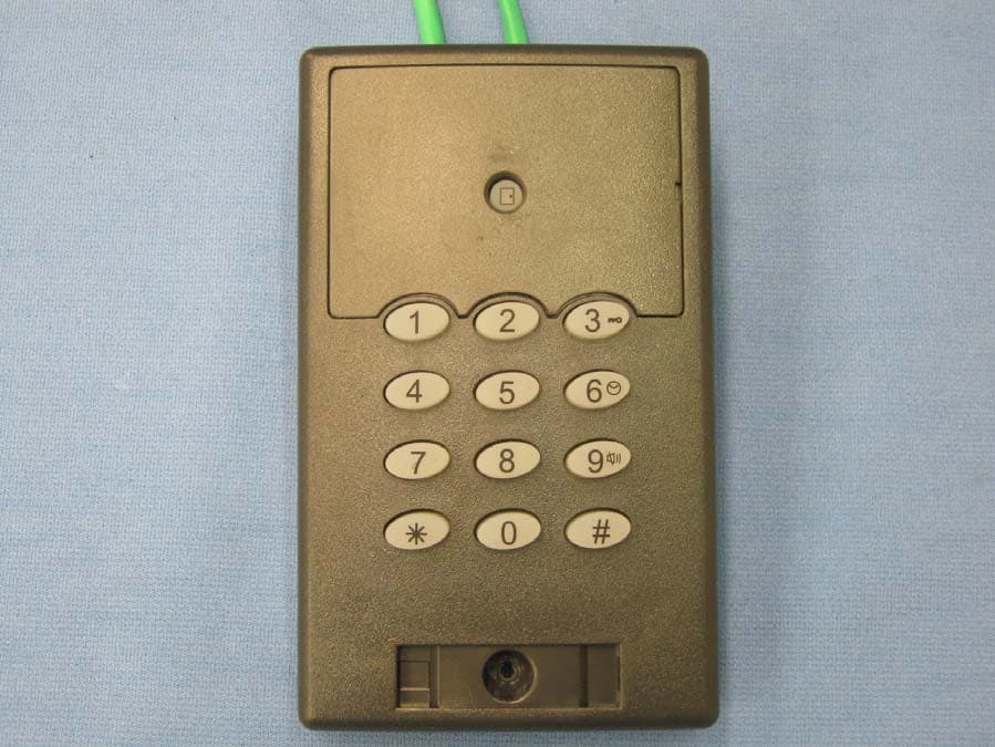
X78SP1M
Sep 19, 2010GProx I Switchplate Reader
Equipment Class
DCD - Part 15 Low Power Transmitter Below 1705 kHz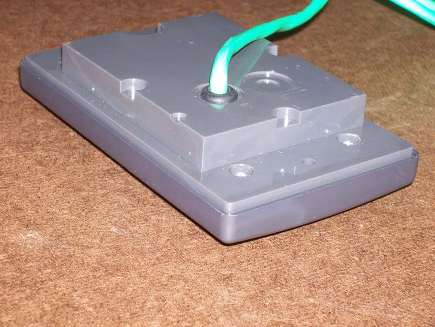
X78SP1A
Sep 19, 2010GProx I Switchplate Reader Keypad
Equipment Class
DCD - Part 15 Low Power Transmitter Below 1705 kHz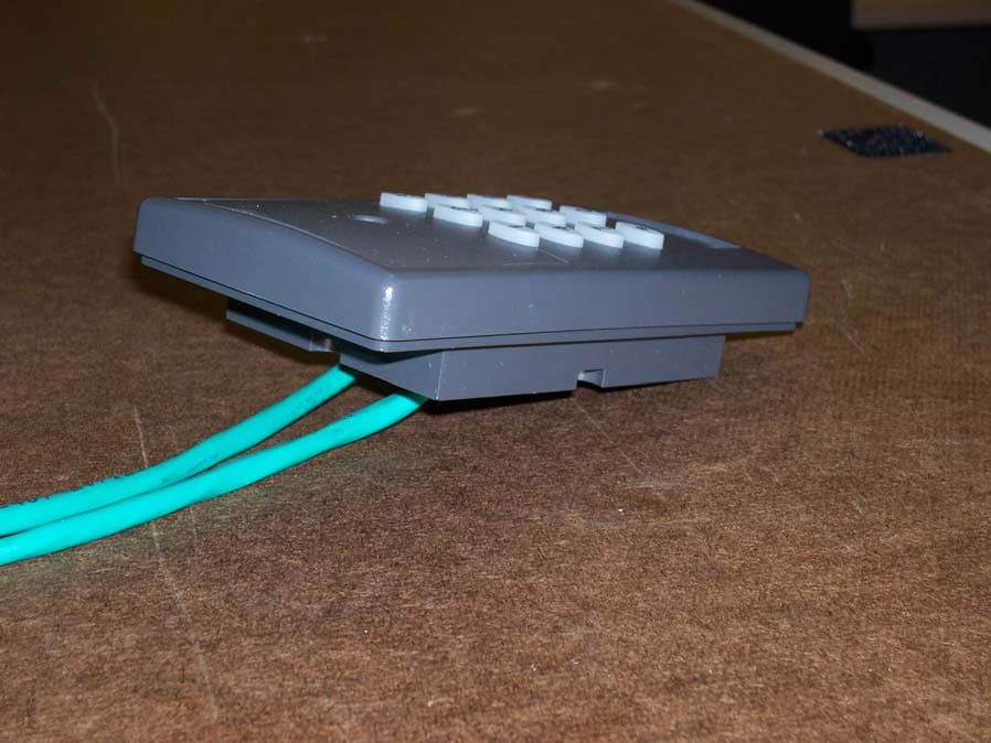
X78SP2M
Sep 06, 2010GProx II Switchplate Reader Keypad
Equipment Class
DCD - Part 15 Low Power Transmitter Below 1705 kHz
X78SP2N
Sep 06, 2010GProx II Switchplate Reader
Equipment Class
DCD - Part 15 Low Power Transmitter Below 1705 kHz
X78SP2A
Sep 06, 2010GProx II Switchplate Reader Keypad
Equipment Class
DCD - Part 15 Low Power Transmitter Below 1705 kHz