X8CEPOOLEPOOL
Dongguan Southstar Electronics Limited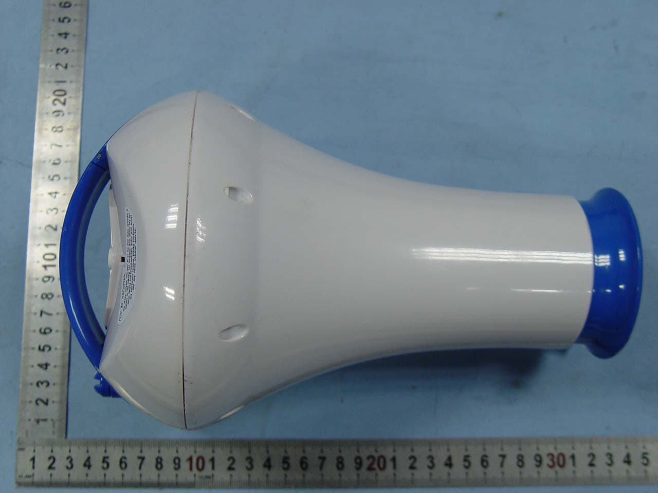
Click to zoom
Application Details
- Equipment Class
- DSC - Part 15 Security/Remote Control Transmitter
- Date of Grant
- Mar 23, 2010
- Application Purpose
- Original Equipment
- Date of Application
- Mar 23, 2010
- Equipment Note
- EPOOL
- Frequency Range
- 433.92000000 - 433.92000000
- Country
- China
Documents & Files
Document Text
Text extracted from the exhibit documents filed with the FCC. Open a document above to read the original.
Users Manual
OWNER’S MANUAL MODEL 4817 & 4819 IMPORTANT DO NOT RETURN PRODUCT TO STORE For technical assistance and missing parts, call Customer Service toll-free 1.888.339.2546 (press 135 at any time) Monday through Friday, 8 am to 5:00 pm MST IMPORTANT SAFETY RULES Read all instructions BEFORE assembling and using this product. KEEP THIS MANUAL. 2KEEP THIS MANUAL IMPORTANT Read all instructions BEFORE setting up and using this product. KEEP THIS MANUAL. Table of Contents 1. For Best Results . . . . . . . . . . . . . . . . . . . . . . . . . . . . . . . . . . . . . 3 2. About e POOL ™ . . . . . . . . . . . . . . . . . . . . . . . . . . . . . . . . . . . . . . 4 3. Safety Warnings . . . . . . . . . . . . . . . . . . . . . . . . . . . . . . . . . . . . . 5 4. Getting Started . . . . . . . . . . . . . . . . . . . . . . . . . . . . . . . . . . . . . 6 Contents . . . . . . . . . . . . . . . . . . . . . . . . . . . . . . . . . . . . . . . . . . . . . 6 Know Your Pool or Spa . . . . . . . . . . . . . . . . . . . . . . . . . . . . . . . . . . . . 6 5. Calculating Pool/Spa Volume . . . . . . . . . . . . . . . . . . . . . . . . . . . . 7 6. Sensor Setup . . . . . . . . . . . . . . . . . . . . . . . . . . . . . . . . . . . . . . . 8 7. Receiver Programming . . . . . . . . . . . . . . . . . . . . . . . . . . . . . . . . 9 Receiver Setup . . . . . . . . . . . . . . . . . . . . . . . . . . . . . . . . . . . . . . . . . 9 Main Menu . . . . . . . . . . . . . . . . . . . . . . . . . . . . . . . . . . . . . . . . . . 13 pH Offset . . . . . . . . . . . . . . . . . . . . . . . . . . . . . . . . . . . . . . . . . . . 13 8. Storage, Maintenance & Care . . . . . . . . . . . . . . . . . . . . . . . . . . . 14 Winter or Extended Storage . . . . . . . . . . . . . . . . . . . . . . . . . . . . . . . 14 Battery and pH Sensor Replacement . . . . . . . . . . . . . . . . . . . . . . . . . . 15 9. Good Things to Know About Pools & Water . . . . . . . . . . . . . . . . . . 18 Water Balance . . . . . . . . . . . . . . . . . . . . . . . . . . . . . . . . . . . . . . . . 18 Water & pH . . . . . . . . . . . . . . . . . . . . . . . . . . . . . . . . . . . . . . . . . . 18 Chlorination and Sanitation . . . . . . . . . . . . . . . . . . . . . . . . . . . . . . . . 19 10. Frequently Asked Questions . . . . . . . . . . . . . . . . . . . . . . . . . . . . 20 11. Trouble Shooting Guide . . . . . . . . . . . . . . . . . . . . . . . . . . . . . . . 22 12. Glossary of Terms . . . . . . . . . . . . . . . . . . . . . . . . . . . . . . . . . . . 24 13. Limited Warranty Statement . . . . . . . . . . . . . . . . . . . . . . . . . . . . 26 14. FCC Statement . . . . . . . . . . . . . . . . . . . . . . . . . . . . . . . . . . . . . 27 Please visit our website, www.game-group.com, for updates to these instructions. 3KEEP THIS MANUAL Diagram A Diagram B Glass lens Glass lens 1. Doing it right the first time. Before using this product, read the manual and follow the step-by-step Quick Setup instructions. 2. A fresh start. Have your pool water professionally tested and properly balanced before using ePOOL. ePOOL is not guaranteed to work on pools or spas with grossly unbalanced chemical levels and/or severe bacterial growth. 3. First things first. Insert battery in floating unit and place in pool before you plug in the indoor receiver. You may receive data within the first 15 minutes. Please allow 4-6 hours for ePOOL to acclimate to your pool chemistry before making any chemical adjustments. 4. Know your pool. ePOOL bases its treatment recommendations on the infor- mation you provide it. During set up, it is important that you give it accurate information about your pool’s size and type. 5. Establish good communication. The ePOOL floating unit and the indoor receiver communicate best when they are in line of sight of each other and no more than 100 feet apart (see Diagram A). We recommend you place the receiver next to a window that has a direct view of your pool. 6. Prevent loss of communication. Do not place anything over the floating unit or obstruct the communication of the indoor receiver by placing something large in front of it. If you use a pool cover, create a space for ePOOL to float freely. 7. Handle with care. If you remove the cap on the floating unit, avoid touching the glass lens on the bottom. Never set the floating unit down without the cap in place or you will damage the glass lens (see Diagram B). 8. Prevent damage. ePOOL is intended for 24/7 use. However, you should remove the floating unit during periods of high pool use or severe weather conditions. 9. Protect and maintain. The glass lens must be kept moist. Always lock the bottom cap on the floating unit with the wet sponge inside when the unit is out of water for any length of time. 10. Receiver care. The receiver is not intended for outdoor use. Always keep the receiver indoors in a cool and dry place and in a direct line of sight of the floating unit. 1. FOR BEST RESULTS 4KEEP THIS MANUAL 2. ABOUT ePOOL™ Congratulations, you’ve just purchased the most exciting innovation in the pool and spa industry. ePOOL is a revolutionary accessory for your pool or spa which eliminates the complicated calculations and the guesswork of confusing test strip kits. ePOOL measures your pool chemistry and advises you how to OPTIMALLY maintain your pool or spa for maximum safety and comfort. ePOOL is personalized to your pool or spa through the setup process. ePOOL takes the guesswork out of pool maintenance because it tells you exactly what you need to do to keep your pool balanced, safe and healthy. Simple to Use ePOOL functions as a two piece system, a floating sensor and an indoor receiver. The sensor floats in the pool and analyzes the chemical levels in the water. This information is transmitted to the receiver. When your pool’s chemical balance is good, the receiver will display a green light. When your chemicals are out of bal- ance, the receiver will alert you with a blinking red light as well …
Text truncated - open the document above for the full version.
Block Diagram
Applicant:Dongguan Southstar Electronics Limited FCC ID:X8CEPOOL Block Diagram Antenna (433.92MHz)
ID Label/Location Info
FCC Certification Label Sample
ID Label/Location Info
FCC Certification Label Location Sample Label location
Internal Photos
Antenna
Operational Description
Applicant:Dongguan Southstar Electronics Limited FCC ID:X8CEPOOL Operation Description The transmitter is a universal SDR RF transmitter chip AX5051. The T1 (AX5051) has an integrated RF frond end with modulator, communication controller and communicates the microcontroller via a SIP buss. U1(ATMEGA32U4-AU) is a High Performance, Low Power AVR 8-Bit Microcontroller used to interface with the radio frequency chip T1 on the SIP buss, read and report sensor voltage, then sensor voltage is buffered by U9 (MCP6234-E) a low power general purpose operation amplifier. The PH (Power of Hydrogen) and ORP (oxidation reduction potential) sensors are high impedance and thus must be buffered by U9 to produce accurate readings as the sensors work. The temperature sensor uses an NTC (Negative temperature coefficient) resistor to indicate the ambient temperature of the transmitter unit. Finally, all information delivered to the air by antenna. Antenna is formed by two copper wire configured in a dipole. Common grounding on PCB is not connected to real external ground. Power supply is DC 6V by four “AA” batteries.
Schematics
11-30-2009 11-30-2009Bryan W. McCoy e-pool FL AC2026 11 REV:SIZE:CODE: DRAWN:DATED: DATED:CHECKED: QUALITY CONTROL:DATED: DATED:RELEASED: COMPANY: TITLE: DRAWING NO: SHEET: OFSCALE: REVISION RECORD APPROVED:ECO NO:LTRDATE: 123456 D C B A C D B A Place AGND1 Guard Ring Around PH+ and ORP+ Nets Do not Install in Production 1 PD3 2 PD4 3 GND 4 VCC 5 GND 6 VCC 7 PB6 8 PB7 24 PC1 23 PC0 22 ADC7 21 GND 20 AREF 19 ADC6 18 AVCC 17 PB5 25 PC2 26 PC3 27 PC4 28 PC5 29 PC6 30 PD0 31 PD1 32 PD2 16 PB4 15 PB3 14 PB2 13 PB1 12 PB0 11 PD7 10 PD6 9 PD5 U1 ATMEGA88PA D1 NI R4 NI 1 GND 2 VIN 4 EN 3 VOUT U6 NCP698SQ33T1G 1 GND 2 VIN 4 EN 3 VOUT U7 NCP698SQ13T1G L2 10uH 1 MISO 2 SCK 3 RST 6 VCC 5 MOSI 4 GND J4 ISP_HEADER_6 D4 J2-1 J2-2 J2-3 J2-4 J2-5 R868.1 R1268.1 C19 0.1礔 C38 1000pF C3 0.1礔 C32 0.1礔 C23 1礔 C24 1礔 C25 1礔 C30 1礔 R14 1.5k J3-1 J3-2 R18 100k R1610R R1710R C39 0.1礔 R7 1k U2 AB-12.000MHZ-B2 R6 0R L9 10uH C27 1000pF C40 1000pF C41 18pF C42 18pF R131k R15 1k 1 PH+ 2 PH-_AND_ORP- 3 ORP+ 4 TEMP_SENSE+ 5 TEMP_SENSE- J1 TRX_1 1 AO 2 A- 3 A+ 4 VDD 5 B+ 6 B- 7 BO 14 DO 13 D- 12 D+ 11 VSS 10 C+ 9 C- 8 CO U9 MCP6234-E/ST R9 10k C8 0.1礔 C9 0.1礔 C10 0.1礔 R3100 C6 0.1礔 R5100R1100 R2100 R11 10k C5 0.1礔 R1910R C36 0.1礔 L10 10uH C37 1000pF R10 10k C11 8.2pF C13 7.6pF L4 18nH L5 18nH L6 33nH L7 33nH C28 56pF C29 56pF C31 100nF C14 100nF C15 100nF C16 56pF C17 100nF C18 56pF C20 100nF C21 100nF C22 4.7uF 1 NC1 2 VDD3 3 GND1 4 ANTP 5 ANTN 6 GND2 7 VDD2 21 NC3 20 VDD_IO 19 IRQ 18 TST3 17 MOSI 16 MISO 15 CLK 22 GND4 23 NC4 24 VREG 25 NC5 26 VDD1 28 CLK16N 14 SEL 13 SYSCLK 12 RESET_N 11 GND3 10 TST2 9 TST1 8 NC2 27 CLK16P 29 G1 30 G2 31 G3 32 G4 33 G5 34 G6 38 GG1 39 GG2 37 G9 36 G8 35 G7 40 GG3 41 GG4 T1 AX5051 J6-1 J6-2 J6-3 J6-4 J6-5 J6-6 J6-7 J6-8 J6-9 J6-10 U3 AB-16.000MHZ-B2 C26 4.7uF 1 2 ANTDP 3.3V LED2_RED LED1_GREEN D- D+ ID GND BAT_OUT PH+_OUT ORP+_OUT TS+_OUT D- GND AX_EE_RXD AX_EE_TXD D+CON AX_EE_XCK AX_IRQ 3.3V 1.3V 1.3V 3.3V D- D+ 3.3V MISO SCK RST VCCP VCC 3.3V MISO SCK RST 3.3V LED1_GREEN 3.3V 3.3V IDAX_SS 1.3V 3.3V PH+ TS+ 3.3V ORP+ TS+_OUT PH+_OUT PH+ TS+ BATDIV VCC ORP+_OUT ORP+ TS+ PH+ BAT_OUT PH- 3.3V 3.3V VDD VDD VDD VDD VDD VDD AX_IRQ AX_EE_TXD AX_EE_RXD AX_EE_XCK SYSCLK AX_SS PDF 文件使用 "pdfFactory Pro" 试用版本创建 www.fineprint.cn
Test Report
Page 1 of 29 FCC ID: X8CEPOOL ACCURATE TECHNOLOGY CO. LTD REPORT NO. ATE20100307 APPLICATION CERTIFICATION On Behalf of Dongguan Southstar Electronics Limited EPOOL Model No.: 4819, 4817 FCC ID: X8CEPOOL Prepared for : Dongguan Southstar Electronics Limited Address : F Building, 3 Chengtian Rd., Mintian, Shatian Town, Dongguan, Guangdong, China Prepared by : ACCURATE TECHNOLOGY CO. LTD Address : F1, Bldg. A, Changyuan New Material Port, Keyuan Rd. Science & Industry Park, Nanshan, Shenzhen, Guangdong P.R. China Tel: (0755) 26503290 Fax: (0755) 26503396 Report Number : ATE20100307 Date of Test : March 8-15, 2010 Date of Report : March 16, 2010 Page 2 of 29 FCC ID: X8CEPOOL ACCURATE TECHNOLOGY CO. LTD REPORT NO. ATE20100307 TABLE OF CONTENTS DescriptionPage Test Report Certification 1.GENERAL INFORMATION ..........................................................................................................4 1.1.Description of Device (EUT)....................................................................................................................4 1.2.Description of Test Facility ......................................................................................................................5 1.3.Measurement Uncertainty.........................................................................................................................5 2.MEASURING DEVICE AND TEST EQUIPMENT ..................................................................... 6 3.SUMMARY OF TEST RESULTS................................................................................................... 7 4.THE FIELD STRENGTH OF RADIATION EMISSION ............................................................ 8 4.1.Block Diagram of Test Setup....................................................................................................................8 4.2.The Field Strength of Radiation Emission Measurement Limits..............................................................9 4.3.Configuration of EUT on Measurement ...................................................................................................9 4.4.Operating Condition of EUT ....................................................................................................................9 4.5.Test Procedure ........................................................................................................................................10 4.6.The Field Strength of Radiation Emission Measurement Results ..........................................................11 5.20DB OCCUPIED BANDWIDTH ................................................................................................ 13 5.1.Block Diagram of Test Setup..................................................................................................................13 5.2.The Bandwidth of Emission Limit According To FCC Part 15 Section 15.231(c) ................................13 5.3.EUT Configuration on Measurement .....................................................................................................14 5.4.Operating Condition of EUT ..................................................................................................................14 5.5.Test Procedure ........................................................................................................................................14 5.6.Measurement Result ...............................................................................................................................15 6.DURATION TIME AND SILENT PERIOD MEASUREMENT............................................... 16 6.1.Block Diagram of Test Setup..................................................................................................................16 6.2.Duration Time and silent period measurement according to FCC Part 15 Section 15.231(e)................16 6.3.EUT Configuration on Measurement .....................................................................................................17 6.4.Operating Condition of EUT ..................................................................................................................17 6.5.Test Procedure ........................................................................................................................................17 6.6.Measurement Result ...............................................................................................................................18 7.AVERAGE FACTOR MEASUREMENT .................................................................................... 19 7.1.Block Diagram of Test Setup..................................................................................................................19 7.2.Average factor Measurement according to ANSI 63.4: 2003.................................................................19 7.3.EUT Configuration on Measurement .....................................................................................................20 7.4.Operating Condition of EUT ..................................................................................................................20 7.5.Test Procedure ........................................................................................................................................20 7.6.Measurement Result ...............................................................................................................................21 APPENDIX I ( TEST CURVES) (7 pages) Page 3 of 29 Test Report Certification Applicant : Dongguan Southstar Electronics Limited Manufacturer: Dongguan Southstar Electronics Limited EUT Description : EPOOL (A) MODEL NO.: 4819, 4817 (B) SERIAL NO.: N/A (C) POWER SUPPLY: DC 6V (“AA” batteries 4×) Measurement Procedure Used: FCC Rules and Regulations Part 15 Subpart C Section 15.231 ANSI 63.4: 2003 The device described above is tested by ACCURATE TECHNOLOGY CO. LTD to determine the maximum emission le…
Text truncated - open the document above for the full version.
Test Setup Photos
Radiated emissions test < 1GHz Radiated emissions test > 1GHz
Contact Information
Applicant
lb fan(Manager of R&D Dept. Electronics)
Test Firm
Accurate Technology Co., Ltd.Sean Liu
Technical Specifications
| # | Rule Parts | Frequency Range | Power Output |
|---|---|---|---|
| 1 | 15.231(e) | 433.92 MHz - 433.92 MHz | - |
Other Applications from Dongguan Southstar Electronics Limited
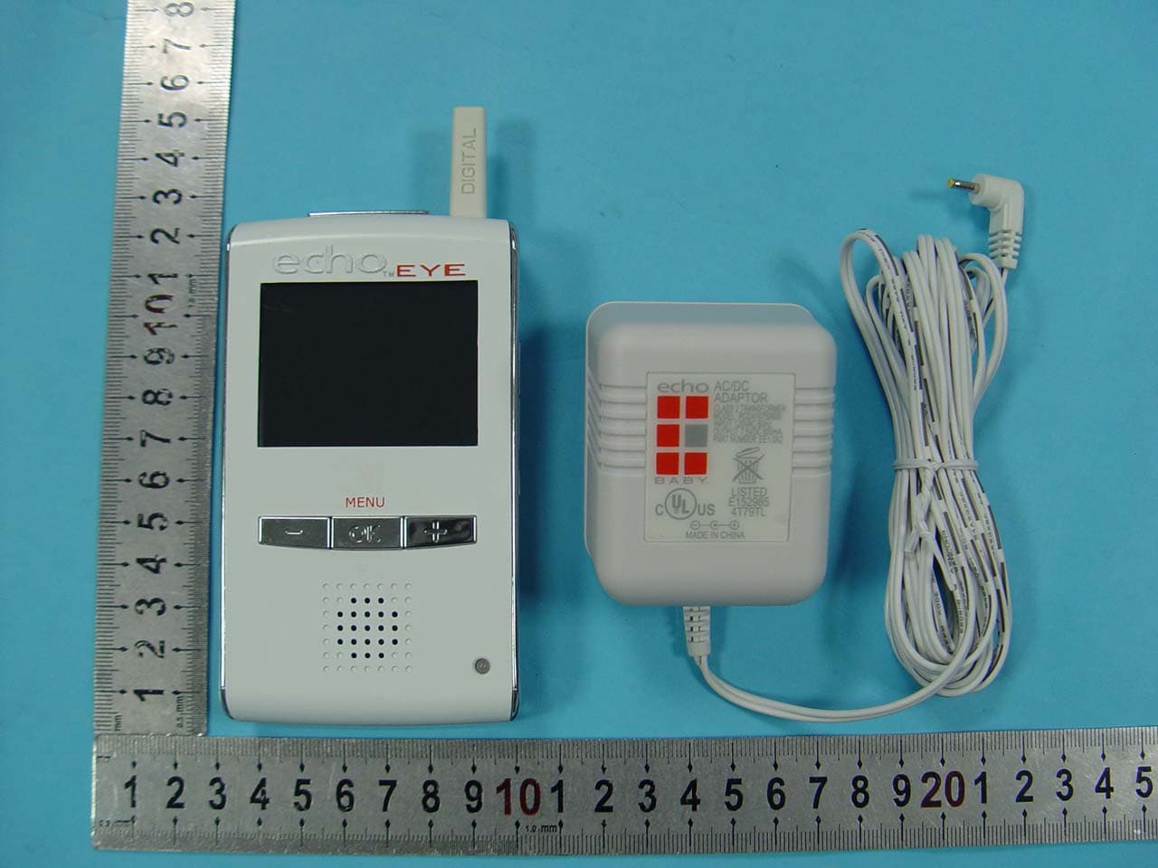
X8C-EE10A1
Nov 04, 2010echoTM EYE for Receiver Unit
Equipment Class
DSS - Part 15 Spread Spectrum Transmitter
X8C-EE10A2
Nov 01, 2010echoTM EYE for Camera unit
Equipment Class
DSS - Part 15 Spread Spectrum Transmitter
X8CWS-2000
Apr 21, 2010Smart Meter Auto Leveler
Equipment Class
DSC - Part 15 Security/Remote Control Transmitter