X8CWS-2000Smart Meter Auto Leveler
Dongguan Southstar Electronics Limited
Click to zoom
Application Details
- Equipment Class
- DSC - Part 15 Security/Remote Control Transmitter
- Date of Grant
- Apr 21, 2010
- Application Purpose
- Original Equipment
- Date of Application
- Apr 21, 2010
- Equipment Note
- Smart Meter Auto Leveler
- Frequency Range
- 433.92000000 - 433.92000000
- Country
- China
Documents & Files
Document Text
Text extracted from the exhibit documents filed with the FCC. Open a document above to read the original.
Users Manual
OWNERS MANUAL MODEL WS-2000 - 1 - Model # WS-2000 Wireless Water Auto-Leveler System The SmartMeter technology is a breakthrough in Auto-Leveler systems. Kona Labs has included a high quality Toro Professional water valve. We have tested this valve with our valve controller and feel that it gives great results. At Kona Labs we are committed to customer satisfaction. If you are not satisfied in any way, or are experiencing any difficulties, please feel free to contact our technical team for assistance. We have tried to keep these instructions as simple as possible. Please read these directions carefully. Read ALL INSTRUCTIONS BEFORE setting up and using this product OWNERS MANUAL MODEL WS-2000 - 2 - Table of Contents A. Overview of the SmartMeter Fill System Pod Sensor Valve Controller Water Valve B. Pre-Installation Decisions MODE 1 or MODE 2 Volume of Water Flow Preferred Water Level C. Installation of the SmartMeter Fill System TIPS Installation of the Pod Sensor Installation of the Water Valve Installation of the Valve Controller D. Care of the SmartMeter Fill System E. Programming Quick Reference Guide F. Trouble Shooting G. Glossary of Terms H. Warranty I ˊ FCC Statement OWNERS MANUAL MODEL WS-2000 - 3 - The SmartMeter Fill System The SmartMeter was invented to help solve problems associated with manually filled pools. This system has three major components. These components are thePod Sensor, the Valve Controller and the remote Water Valve. A Toro Professionals Series valve is included with the system to help insure success. The Toro valve specifications allow more than 180 feet of 18GA wire. Combined with typical radio transmission ranges in excess of 20 feet you should have over 200 feet of distance between the “Pod Sensor” in the pool and the “Water Valve”. Three major components - Pod Sensor, Valve Controller and remote Water Valve Overview of the SmartMeter Fill System The System works by sending water level signals to the remote controller. The “Pod Sensor” sends wireless signals by radio to the nearby “Valve Controller”. The Valve Controller receives the level signal and operates the “Water Valve”. Upon installation, the Valve Controller is programmed for a preferred “set level”. The “set level” for the “Pod Sensor” should be at the same level as the preferred level of operation for your pool and spa. This level should also coincide with the suggested level of the water line at the Pod Sensor finger. All of this is explained in this manual. OWNERS MANUAL MODEL WS-2000 - 4 - The SmartMeter Fill System has two modes of operation. MODE 1 provides a continuous auto-fill function and MODE 2 is considered a water saver mode. Mode 1 measures water level and updates Water Valve every 10 minutes, 24 hours a day. Mode 2 measures water less frequently. Mode 2 “sleeps for 23 hours each day and only takes measurements during one hour of “wake” time. During the fill cycle “wake” hour, water level measurements and Water Valve updates occur 6 times, once every 10 minutes. During installation the fill cycle “wake” hour is predetermined and programmed by you. The SmartMeter Fill System was intended as an upgrade for pools that currently do not have an auto-fill system or an auto-leveler. The SmartMeter can also upgrade pools with float-type mechanical auto-fill systems. Pod Sensor The Pod Sensor measures the water level. It fits under a deck lid. Refer to Installation Instructions for more specific details on installation options. Valve Controller The Valve Controller receives the wireless signal from the Pod Sensor and operates the Water Valve accordingly. The Valve Controller is your only programming interface. On this controller are a RESET button along with a GREEN LED and a RED LED. The Valve Controller contains 6 “AA” batteries. OWNERS MANUAL MODEL WS-2000 - 5 - This figure shows a drawing of the programming interface of the Valve Controller Water Valve A Toro Professional 1” Valve is included with the SmartMeter Fill System. This valve has a variable flow function. The Water Valve allows you to have some control over the volume and flow of water sent into the pool, spa or water feature. The Toro Professional Water Valve included can deliver a wide range of flow requirements. This valve can reliably deliver as little as 0.1 gallons per minute. MODE TYPE FLOW MAXIMUM MIN/DAY MAXIMUM GAL/DAY MINIMUM GAL/DAY MODE 1 Rapid Auto-Fill 0.1 gal/min 1440 144 0 MODE 2 “Water Saver” Mode 0.1 gal/min 60 6 0 MODE 1 Rapid Auto-Fill 40 gal/min 1440 57600 0 MODE 2 “Water Saver” Mode 40 gal/min 60 2400 0 This data table is provided for reference only. Data is based on specifications from Toro on the 1” female NPT and for the TPVF100DC at typical line pressures. Your installation will be different. For installation consult a plumbing professional. Pre-Installation Decisions OWNERS MANUAL MODEL WS-2000 - 6 - CHOOSE Mode 1 or Mode 2 Mode 1 is considered a continuous auto-fill method. Mode 2 is considered the “water saver” method. This is an important feature of the SmartMeter WS-2000. Mode 2 allows for a water loss indication and automatic water shut off. There is no water loss detection or automatic shut off capabilities for Mode 1. MODE 1 - rapid auto-fill mode (No Water Saver Function) xEvery 10 minutes measures water level and updates valve xWater Valve turns off only if Pod Sensor signal is lost or batteries low MODE 2 - regular fill mode. (“Water Saver”) x 23 hours a day does NOT take measurements x 1 hour per day measures water level and updates valve 6 times (Once every 10 minutes during hour of wake time) x Water Valve automatically shuts off if “set” level is not achieved for three consecutive days If SmartMeter detects that set level was not achieved for three consecutive days it shuts off the Water Valve and the RED “error” LED light flashes. This indicates a possible water loss or leak. This automatic shut-off function is intended to save water and to inform you of a possible water loss. Visual…
Text truncated - open the document above for the full version.
Block Diagram
Applicant:Dongguan Southstar Electronics Limited FCC ID:X8CWS-2000 Block Diagram
ID Label/Location Info
FCC Certification Label Sample
ID Label/Location Info
FCC Certification Label Location Sample Label location
Internal Photos
Antenna
Operational Description
Applicant:Dongguan Southstar Electronics Limited FCC ID:X8CWS-2000 Operation Description The transmitter is a universal SDR RF transmitter chip AX5051. The U1(AX5051) has an integrated RF frond end with modulator and demodulator, communication controller and communicates the microcontroller via a SIP buss. U4(MCP1700T-3302E/TT) is a power management chip and provides host with 3.3V power. U6(MC14521BDR2G) is the source of the clock of 1 second. U3(ATMEGA88PA-AU) is a High Performance, Low Power AVR 8-Bit Microcontroller used to interface with the radio frequency chip U1 on the SIP buss, read data from U2(PIC18F24J11-I/SS), and report data. Finally, all information is measured and reported to the receiver unit. Antenna is formed by two copper wire configured in a dipole. Common grounding on PCB is not connected to real external ground. Power supply is DC 6V by four “AA” batteries.
Schematics
2/19/10 9:23 AM f=0.45 /home/kevin/eagle/kona pod Rev2/Pod.sch (Sheet: 1/1) RevisionDate 2.001/23/2010 2.102/19/2010 Description Released to fab Change R21 from 750K to 820K Change C21 from 82pF to 27pF GND GND GND VDD VDD 33nH 33nH VDD VDD 100nF GND VDD33 15nH 15nH 22pF22pF1u 8pF6.8pF 100nF 100nF GND GND 56pF 100R 100R 100R 220pF 220pF GND GND GNDGND GNDGND MCP1700T-3302E/TT MCP9700T-E/TT (DNI for production) 1u GND GND VDD33 VDD33 VDD33 4k7 10u GND VDD33 GND GND GND PINHD5 PINHD2X42MM 100nF VDD33 GND ATMEGA88PA-AU FOXSLF/120-20 22pF22pF GND VDD33PIC18F24J11-I/SS 10R (0R for production) 10R (0R for production) 10R (0R for production) 10uH 0805 GND 100nF 100nF GND 100nF GND 1k5 68R 68R 4k7 4k7 VDD33 2M (DNI for production) GND 2M (DNI for production)2M (DNI for production)2M (DNI for production) 0R (DNI for production) 0R (DNI for production) 0R (DNI for production) 0R (DNI for production) 4k7 VDD33 PINHD2X3 GND VDD33 1u 10R (0R for production) PINHD6 LED (DNI for production) 220R (DNI for production) VDD33 MC14521BDR2G AB26T-32.768KHZ 820K 10M 22pF27pF GND GND VDD33 4k74k7 GND BAT54T1G 120k 1M GND ANT ANT FOXSLF/160-20 GND L1 L2 C105 L3 L4 C9C10C102 C1C2 C107 C106 C108 B1 B2 B3 C100 C101 GND 1 VOUT 2 VIN 3 U4 VDD 1 VOUT 2 GND 3 U5 C11 R4 C15 P$1 P$1 P$1 P$1 P$1 P$1 P$1 P$1 1 2 3 4 5 J3 12 34 56 78 J2 C13 PB5(SCK) 17 PB7(XTAL2/TOSC2) 8 PB6(XTAL1/TOSC1) 7 GND 3 GND 5 VCC 4 VCC 6 GND 21 AREF 20 AVCC 18 PB4(MISO) 16 PB3(MOSI/OC2) 15 PB2(SS/OC1B) 14 PB1(OC1A) 13 PB0(ICP) 12 PD7(AIN1) 11 PD6(AIN0) 10 PD5(T1) 9 PD4(XCK/T0) 2 PD3(INT1) 1 PD2(INT0) 32 PD1(TXD) 31 PD0(RXD) 30 ADC7 22 ADC6 19 PC5(ADC5/SCL) 28 PC4(ADC4/SDA) 27 PC3(ADC3) 26 PC2(ADC2) 25 PC1(ADC1) 24 PC0(ADC0) 23 PC6(/RESET) 29 U3 X2 C12C14 _MCLR 1 AN0/RA0 2 AN1/RA1 3 VREF-/CVREF/AN2/RA2 4 VREF+/AN3/RA3 5 VCAP 6 _SS/HLVDIN/AN4/RA5 7 VSS 8 OSC1/CLKI/RA7 9 OSC2/CLKO/RA6 10 T1OSO/T1CKI/RC0 11 _UOE/T1OSI/RC1 12 AN11//RC2 13 SCK1/SCL1/RC3 14 SDI1/SDA1/RC4 15 SDO1/RC5 16 TX/CK/RC6 17 SDO1/RX1/DT1/RC7 18 VSS 19 VDD 20 INT0//AN12/RB0 21 RTCC/AN10/RB1 22 AN8/RB2 23 AN9/RB3 24 RB4 25 RB5 26 PGC/RB6 27 PGD/RB7 28 U2 R2 R3 R6 L8 C16 C17 C18 R7 R5 R8 R9 R10 R11R12R13R14 R15 R16 R17 R18 R19 16 25 34 J1 C19 R1 1 2 3 4 5 J5 6 LED1 R20 VDD 16 VDD' 5 VSS 8 VSS' 3 RESET 2 IN1 9 OUT1 7 Q18 10 Q19 11 Q20 12 Q21 13 Q22 14 Q23 15 IN2 6 OUT2 4 Q24 1 U6 X3 R21 R22 C20C21 R23R24 D1 R25 R26 A1 A2 X4 NC1 1 VDDA2 2 GND1 3 ANT1 4 ANT2 5 GND2 6 VDDA3 7 NC2 8 NC3 9 NC4 10 GND3 11 RESET_N 12 SYSCLK 13 SEL 14 CLK 15 MISO 16 MOSI 17 NC5 18 IRQ 19 VSUP 20 NC6 21 GND4 22 NC7 23 VREG 24 NC8 25 VDDA1 26 CLK16P 27 CLK16N 28 U1G$1 GND1 30 U1G$2 TP5 TP6 TP7 TP8 TP9 TP10 TP11 TP12 GND GND VDD VDD33 AX_IRQ AX_IRQ AX_MOSI AX_MOSI AX_MISO AX_MISO VDDA1 PGC PGC PGC PGD PGD PGD /MCLR /MCLR /MCLR TOUCH4 TOUCH4 TOUCH2 TOUCH2 VCCP VCCPID ID D- D- D+ D+ TOUCH1 TOUCH1 TOUCH3 TOUCH3 D-CON D+CON VCAP SCL SCL SDA SDA TEMP TEMP AX_CLK AX_CLK AX_SEL AX_SEL RESET RESET MOSI MOSI MISO MISO SCK SCK VSUP PICWAKEUP PICWAKEUP PICWAKEUP SIG1 SIG1 SIG1 IN2 OUT2 BATT BATT AX5051 LNA PA RF Freq T/R Xtal Osc ADC IF Filter VReg Encoder Framing FIFO Modulator Demodulator AGC Serial Communications / control Divider Place these resistors near touchpads VCCP max 10V 10V * 120 / 1120 = 1.071428571V VREF = 1.1V
Test Report
Page 1 of 27 FCC ID: X8CWS-2000 ACCURATE TECHNOLOGY CO. LTD REPORT NO. ATE20100455 APPLICATION CERTIFICATION On Behalf of Dongguan Southstar Electronics Limited Smart Meter Auto Leveler Model No.: WS-2000 FCC ID: X8CWS-2000 Prepared for : Dongguan Southstar Electronics Limited Address : F Building, 3 Chengtian Rd., Mintian, Shatian Town, Dongguan, Guangdong, China Prepared by : ACCURATE TECHNOLOGY CO. LTD Address : F1, Bldg. A, Changyuan New Material Port, Keyuan Rd. Science & Industry Park, Nanshan, Shenzhen, Guangdong P.R. China Tel: (0755) 26503290 Fax: (0755) 26503396 Report Number : ATE20100455 Date of Test : April 14-16, 2010 Date of Report : April 16, 2010 Page 2 of 27 FCC ID: X8CWS-2000 ACCURATE TECHNOLOGY CO. LTD REPORT NO. ATE20100455 TABLE OF CONTENTS Description Page Test Report Certification 1. GENERAL INFORMATION.......................................................................................................4 1.1. Description of Device (EUT)................................................................................................................ 4 1.2. Description of Test Facility.................................................................................................................. 5 1.3. Measurement Uncertainty..................................................................................................................... 5 2. MEASURING DEVICE AND TEST EQUIPMENT..................................................................6 3. SUMMARY OF TEST RESULTS................................................................................................7 4. THE FIELD STRENGTH OF RADIATION EMISSION.........................................................8 4.1. Block Diagram of Test Setup................................................................................................................ 8 4.2. The Field Strength of Radiation Emission Measurement Limits.......................................................... 9 4.3. Configuration of EUT on Measurement............................................................................................... 9 4.4. Operating Condition of EUT................................................................................................................ 9 4.5. Test Procedure.................................................................................................................................... 10 4.6. The Field Strength of Radiation Emission Measurement Results...................................................... 11 5. 20DB OCCUPIED BANDWIDTH.............................................................................................12 5.1. Block Diagram of Test Setup.............................................................................................................. 12 5.2. The Bandwidth of Emission Limit According To FCC Part 15 Section 15.231(c)............................ 12 5.3. EUT Configuration on Measurement................................................................................................. 13 5.4. Operating Condition of EUT.............................................................................................................. 13 5.5. Test Procedure.................................................................................................................................... 13 5.6. Measurement Result........................................................................................................................... 13 6. DURATION TIME AND SILENT PERIOD MEASUREMENT............................................14 6.1. Block Diagram of Test Setup.............................................................................................................. 14 6.2. Duration Time and silent period measurement according to FCC Part 15 Section 15.231(e)............ 14 6.3. EUT Configuration on Measurement................................................................................................. 15 6.4. Operating Condition of EUT.............................................................................................................. 15 6.5. Test Procedure.................................................................................................................................... 15 6.6. Measurement Result........................................................................................................................... 16 7. AVERAGE FACTOR MEASUREMENT.................................................................................17 7.1. Block Diagram of Test Setup.............................................................................................................. 17 7.2. Average factor Measurement according to ANSI 63.4: 2003............................................................. 17 7.3. EUT Configuration on Measurement................................................................................................. 18 7.4. Operating Condition of EUT.............................................................................................................. 18 7.5. Test Procedure.................................................................................................................................... 18 7.6. Measurement Result........................................................................................................................... 19 APPENDIX I ( TEST CURVES) (7 pages) Page 3 of 27 Test Report Certification Applicant : Dongguan Southstar Electronics Limited Manufacturer : Dongguan Southstar Electronics Limited EUT Description : Smart Meter Auto Leveler (A) MODEL NO.: WS-2000 (B) SERIAL NO.: N/A (C) POWER SUPPLY: DC 6V (“AA” batteries 4×) Measurement Procedure Used: FCC Rules and Regulations Part 15 Subpart C Section 15.231 ANSI 63.4: 2003 The device described above is tested by ACCURATE TECHNOLOGY CO. LTD to determine the maximum emission levels emanating from the device. The maximum emission lev…
Text truncated - open the document above for the full version.
Test Setup Photos
Radiated emissions test < 1GHz Radiated emissions test > 1GHz
Contact Information
Applicant
lb fan(Manager of R&D Dept. Electronics)
Test Firm
Accurate Technology Co., Ltd.Sean Liu
Technical Specifications
| # | Rule Parts | Frequency Range | Power Output |
|---|---|---|---|
| 1 | 15.231(e) | 433.92 MHz - 433.92 MHz | - |
Other Applications from Dongguan Southstar Electronics Limited
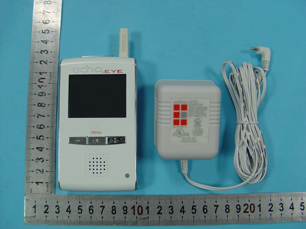
X8C-EE10A1
Nov 04, 2010echoTM EYE for Receiver Unit
Equipment Class
DSS - Part 15 Spread Spectrum Transmitter
X8C-EE10A2
Nov 01, 2010echoTM EYE for Camera unit
Equipment Class
DSS - Part 15 Spread Spectrum Transmitter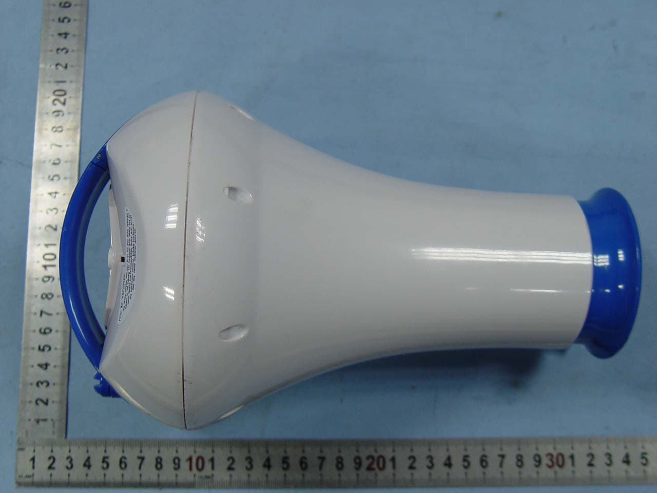
X8CEPOOL
Mar 23, 2010EPOOL
Equipment Class
DSC - Part 15 Security/Remote Control Transmitter