XG531415TParty in my pants
ZHUHAI WINGPOW EROTIC & NOVELTY MANUFACTURING CO., LTD.Application Details
- Equipment Class
- DSC - Part 15 Security/Remote Control Transmitter
- Date of Grant
- Oct 25, 2010
- Application Purpose
- Original Equipment
- Date of Application
- Oct 25, 2010
- Equipment Note
- Party in my pants
- Frequency Range
- 433.92000000 - 433.92000000
- Country
- China
Documents & Files
Document Text
Text extracted from the exhibit documents filed with the FCC. Open a document above to read the original.
Users Manual
Introduction to Design Plan of Transmitter Transmitter Antenna 4F functional button ON/OFF button LED display Operating Principle • Master Control Chip conducts data analysis and identification on button demand through button scan. Analog sign al will be converted to digital signal through A/D Converter, and corresponding code signal will be output following operation. • After the user’s button demand is processed to code signal , the code signal will be loaded to high-frequency local oscillator signal by frequency mixing so as to form radio-frequency signal satisfying requirement of transmission. • Code signal is loaded to radio-frequency signal and is transmitted to surrounding environment by antenna via transmission circuit, in order to control action of receiver. Logic Block Diagram Transmission antenna Modulation of high- frequency local oscillator Voltage stabilization and filtering Status display Output of RF carrier signal Master Control Chip Signal Processing Unit A/D Converter and code output Functional button circuit 12V battery as power supply Code signal 433.92M Quartz Crystal Local Resonator Electric Parameters and Properties • Voltage of power supply : 23A battery, 12VDC • Transmission amplitude : Principal wave +17DB Secondary harmonic -18DB • Transmission frequency : 433.92MHZ ( +/- 20PPM ) • Modulation model : AM Application Method • Press Start button of receiver, and the system starts in ready mode ; • Long press ON/OFF button for 3 se conds, the product will work in F1 mode and start vibration ; • Press 4F button of remote-controller, the product will work in F2 mode and accelerate vibration ; • Press 4F button of remote-controller again, the product will work in F3 mode and vibrate at the highest speed ; • Press 4F button of remote-controller again, the product will work in F4 mode and pulse vibration mode. The four modes may change from F1 to F4 repeatedly. • Long press ON/OFF button for 3 se conds again, the product will turn off and stop work ; • Red light of LED can be seen while pressing button. • This device complies with Part 15 of the FCC Rules. Operation is subject to the following two conditions: • (1) this device may not caus eharmful interference, and • (2) this device must accept any interference received, i ncluding interference that may cause undesired operation. • hanges or modifications not expressly approved by the party responsible for compliance • could void the user's autho rity to operate the equipment. • NOTE: This equipment has been tested and found to comply with the limits for a Class B digital device, pursuant to Part 15 of the FCC Rules. These limits are • designed to provide reasonable protec tion against harmful interference in a • residential installation. This equipmen t generates, uses and can radiate radio • frequency energy and, if not install ed and used in accordance with the • instructions, may cause harmful interfer ence to radio comm unications. However, • there is no guarantee that in terference will not occur in a particular installation. • If this equipment does cause harmful interf erence to radio or television reception, • which can be determined by turni ng the equipment off and on, the user is • encouraged to try to correct the interfer ence by one or more of the following • measures: • -- Reorient or relocate the receiving antenna. • -- Increase the separation betwe en the equipment and receiver. • -- Connect the equipment into an outlet on a circuit different • from that to which th e receiver is connected. • -- Consult the dealer or an experi enced radio/TV technician for help.
Block Diagram
Logic Block Diagram Transmission antenna Modulation of high- frequency local oscillator Voltage stabilization and filtering Status display Output of RF carrier signal Master Control Chip Signal Processing Unit A/D Converter and code output Functional button circuit 12V battery as power supply Code signal 433.92M Quartz Crystal Local Resonator
Cover Letter(s)
SCS-F18: Project and Product Certification Representative Authorization Letter Page 1 of 2 Rev 2.0 2206 Ringwood Avenue San Jose, CA 95131 Tel: 408-526-1188 Fax: 408-526-1088 Email: [email protected] Project and Product Certification Representative Authorization Letter Reason for Amendment (current / obsolete) Revision History Approved Date From To Initial Release (current) 1.0 1.0 Revised wording (current) 1.0 2.0 SCS-F18: Project and Product Certification Representative Authorization Letter Page 2 of 2 Rev 2.0 ZHUHAI WINGPOW EROTIC & NOVELTY MANUFACTURING CO., LTD. October 18, 2010 To: SIEMIC, INC. 2206 Ringwood Avenue, San Jose, CA 95131 USA Dear Sir/Madam, Re: Project and Product Certification Representative Authorization Letter We, ZHUHAI WINGPOW EROTIC & NOVELTY MANUFACTURING CO., LTD. hereby authorize SIEMIC, INC. to act as a Certification Body for certifying for the following project(s): (Party in my pants , Model No. : 31415) We affirm that between SIEMIC and ZHUHAI WINGPOW EROTIC & NOVELTY MANUFACTURING CO., LTD. , any difference in understanding, including test plan, measurement methods, applicable standards and relevant procedures and processes have been resolved prior to commencement of testing activities. NO. 35 FIRST ROAD, ZHUHAI BAIJAO NEW TECHNOLOGICAL& INDUSTRIAL PARK, ZHUHAI, CHINA
ID Label/Location Info
FCC Label : FCC ID: XG531415T
ID Label/Location Info
FCC Label Location
Operational Description
Operating Principle • Master Control Chip conducts data analysis and identification on button demand through button scan. Analog sign al will be converted to digital signal through A/D Converter, and corresponding code signal will be output following operation. • After the user’s button demand is processed to code signal , the code signal will be loaded to high-frequency local oscillator signal by frequency mixing so as to form radio-frequency signal satisfying requirement of transmission. • Code signal is loaded to radio-frequency signal and is transmitted to surrounding environment by antenna via transmission circuit, in order to control action of receiver.
Schematics
1 1 2 2 3 3 4 4 DD CC BB AA Ti tl e Nu mberRevisionSize A4 Dat e:20 10 -1 0-17Sheet of File:F:\EDDY\433fs.SCHDraw n By: A 433 M REMOCON EddyZhang 10 0u F/ 6.3 V E0 Vi n 1 GND 2 Vo ut 3 HT 71 33U1 BATTERY 12 V10 4 C02 +12VDC 10 4 C01 VD D R25 Q1 2SC3 355 Q2 ON /OFF 43 3.9 2M Y2 6. 8P C5 27 nH L2 10 4 C3 27 nH L1 An t1 2. 7P C4 2K R1 10 0K 2K R2 1 2 3 45 6 7 8 FS1351 U2 MODE VD D LE D 33 0R R3 +12VDC C 3. 3P C3 15 0n H L SO
Test Report
Report No.: A001P101016001E Page 1 of 18 FCC TEST REPORT For ZHUHAI WINGPOW EROTIC & NOVELTY MANUFACTURING CO., LTD. Party in my pants Model No. : 31415 FCC ID : XG531415T Operating Frequency : 433.92MHz Applicant : ZHUHAI WINGPOW EROTIC & NOVELTY MANUFACTURING CO., LTD. NO. 35 FIRST ROAD, ZHUHAI BAIJAO NEW TECHNOLOGICAL & INDUSTRIAL PARK, ZHUHAI, CHINA Regulation : FCC Part 15 Subpart C Section 15.231 Prepared by : Shenzhen AOV Testing Technology Co., Ltd. 2-6/F, No.5, Yuantou Lane, Tanglang, Taoyuan Street, Nanshan District, Shenzhen, Guangdong, China Test Date : October 16-19, 2010 Date of Report : October 19, 2010 Report No.: A001P101016001E Page 2 of 18 TABLE OF CONTENT Description Page Test Report Declaration 1. GENERAL INFORMATION..................................................................................................4 1.1 General Information....................................................................................................................4 1.2 Test Facility..................................................................................................................................4 1.3 Test Summary.............................................................................................................................5 1.4 Test Instrument Used.................................................................................................................6 2. TRANSMITTER TIME............................................................................................................7 2.1. Rules Part No..............................................................................................................................7 2.2. Limit of transmitter time.............................................................................................................7 2.3. Test result....................................................................................................................................7 3. RADIATION INTERFERENCE............................................................................................9 3.1. Rules Part No..............................................................................................................................9 3.2. Limit of Radiated Disturbances.................................................................................................9 3.3. Test Procedure............................................................................................................................9 3.4. Test Result.................................................................................................................................10 4. BANDWIDTH........................................................................................................................11 4.1. Test Standard............................................................................................................................11 4.2. Limits..........................................................................................................................................11 4.3. Test Procedure..........................................................................................................................11 4.4. Test Result.................................................................................................................................11 5. DUTY CYCLE.......................................................................................................................13 5.1. Test Standard............................................................................................................................13 5.2. Test Procedure..........................................................................................................................13 5.3. Test Result.................................................................................................................................13 6. ANTENNA REQUIREMENT...............................................................................................17 7. PHOTOGRAPH OF TEST..................................................................................................18 Report No.: A001P101016001E Page 3 of 18 TEST REPORT DECLARATION Applicant : ZHUHAI WINGPOW EROTIC & NOVELTY MANUFACTURING CO., LTD. Manufacturer : ZHUHAI WINGPOW EROTIC & NOVELTY MANUFACTURING CO., LTD. EUT Description : Party in my pants Test Procedure Used: FCC Part 15.231 Subpart C The E. U. T. listed below has been completed RFI testing by Shenzhen AOV Testing Technology Co., Ltd at the test site of Bontek Compliance Testing Laboratory Ltd. And the Interference emissions can pass FCC Class B limitations. The test configurations and the facility comply with the radiated and AC line conducted test site criteria in ANSI C63.4-2003. Date of Test: October 16-19, 2010 Prepared by: Project Engineer Reviewer : Project Manager Report No.: A001P101016001E Page 4 of 18 1. GENERAL INFORMATION 1.1 General Information EUT Description : Party in my pants Model No. : 31415 Type of Antenna : Permanent attached Applicant : ZHUHAI WINGPOW EROTIC & NOVELTY MANUFACTURING CO., LTD. NO. 35 FIRST ROAD, ZHUHAI BAIJAO NEW TECHNOLOGICAL & INDUSTRIAL PARK, ZHUHAI, CHINA Manufacturer : ZHUHAI WINGPOW EROTIC & NOVELTY MANUFACTURING CO., LTD. NO. 35 FIRST ROAD, ZHUHAI BAIJAO NEW TECHNOLOGICAL & INDUSTRIAL PARK, ZHUHAI, CHINA 1.2 Test Facility Test Firm : Bontek Compliance Testing Laboratory Ltd. Certificated by FCC, Registration No.: 338263 Address : FL.1, Building H-3, Hua Qiao Cheng East Industrial Area Qiaocheng East Road, Nanshan, Shenzhen, P.R.China Tel : 86-755-86337020 Fax : 86-755-86337028 Report No.: A001P101016001E Page 5 of 18 1.3 Test Summary For the EUT described above. The standards used were FCC Part 15 Subpart C Section 15.231 for Emissions Tests Carried Out Under FCC Part 15 Subpart C Standard Test Items Status Section 15.207 Conducted Emission N/A Transmitter tim…
Text truncated - open the document above for the full version.
Test Setup Photos
Below 1G Above 1G
Contact Information
Applicant
Jinwei He(Head of Engineering)
Test Firm
Bontek Compliance Testing Laboratory LtdTony Wu
Technical Specifications
| # | Rule Parts | Frequency Range | Power Output |
|---|---|---|---|
| 1 | 15.231 | 433.92 MHz - 433.92 MHz | - |
Other Applications from ZHUHAI WINGPOW EROTIC & NOVELTY MANUFACTURING CO., LTD.
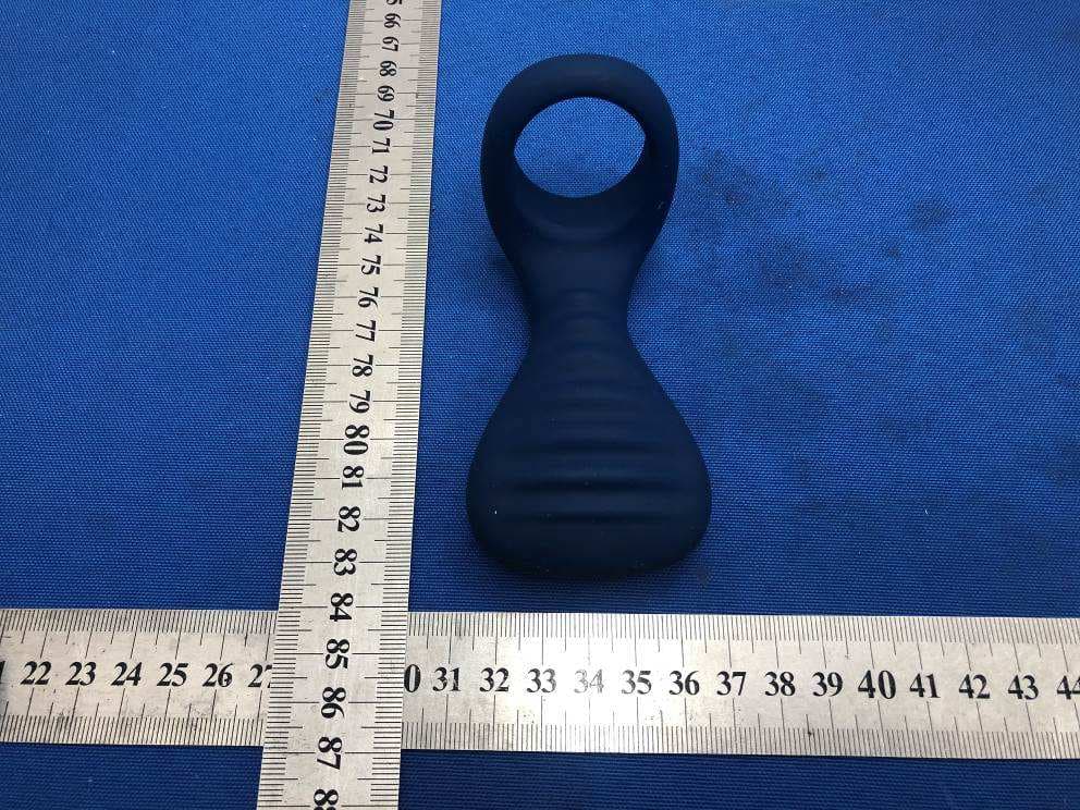
XG5OMBBM05
Dec 29, 2020blueMotion NEX 3
Equipment Class
DTS - Digital Transmission System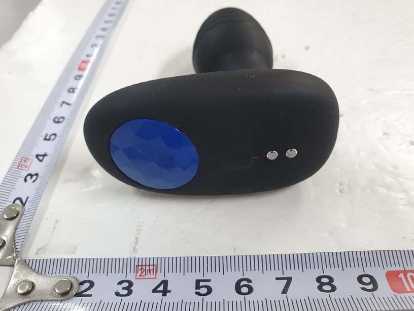
XG5OMBLU01
Dec 21, 2020Lumen
Equipment Class
DTS - Digital Transmission System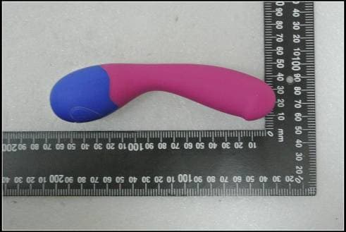
XG5OMBBM02
Jun 09, 2015BlueMotion NEX2
Equipment Class
DSS - Part 15 Spread Spectrum Transmitter
XG5OVOR6T
Sep 22, 2014Massager
Equipment Class
DXX - Part 15 Low Power Communication Device Transmitter
XG5OVOR6R
Sep 22, 2014Massager
Equipment Class
DXX - Part 15 Low Power Communication Device Transmitter