XGR-GW3000V2Gateway MicroRouter
Ambient Systems B.V.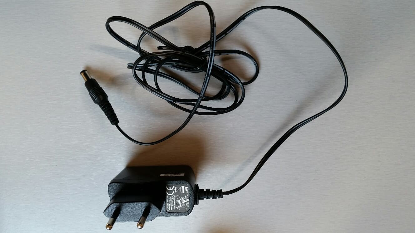
Click to zoom
Application Details
- Equipment Class
- DTS - Digital Transmission System
- Date of Grant
- Jun 10, 2015
- Application Purpose
- Original Equipment
- Date of Application
- Jun 10, 2015
- Equipment Note
- Gateway MicroRouter
- Frequency Range
- 2405.00000000 - 2480.00000000
- Company
- Ambient Systems B.V.
- Country
- Netherlands
Documents & Files
Document Text
Text extracted from the exhibit documents filed with the FCC. Open a document above to read the original.
Users Manual
User Manual User Manual GW 3030v2 side 2..16 (regulatory text on side 15, page 14) User Manual MR3000v2 side 17..30 (regulatory text on side 29, page 13) Model: GW3030v2 Revision P1A USER MANUAL Gateway GW3030 v2.0 Ambient Systems B.V. Page 1 of 15 Demmersweg 66 • 7559 BN Hengelo • The Netherlands T: +31 88 2624368 • F: +31 88 2624399 • www.ambient-systems.net KvK: 08122911 • VAT NL: 81297625381 CHECK.TRACK.TRACE. User Manual This is a draft user manual of a not yet released product. All its contents is subject to change. Product Code(s): 900.100.010.003 (AMB GW3030v2) 901.100.000.003, 901.100.004.003 Model: GW3030v2 Revision P1A USER MANUAL Gateway GW3030 v2.0 Ambient Systems B.V. Page 2 of 15 Demmersweg 66 • 7559 BN Hengelo • The Netherlands T: +31 88 2624368 • F: +31 88 2624399 • www.ambient-systems.net KvK: 08122911 • VAT NL: 81297625381 CHECK.TRACK.TRACE. 1 Table of Contents 2 Preface ......................................................................................................................................................... 3 2.1 What is the MicroRouter MR3000 v2.0 ............................................................................................................ 3 2.2 Features ............................................................................................................................................................ 3 2.3 Conventions ...................................................................................................................................................... 3 2.4 Further Information ................................................................................... Fout! Bladwijzer niet gedefinieerd. 3 Introduction ................................................................................................................................................. 5 3.1 About This Manual ............................................................................................................................................ 5 3.2 Related Documentation .................................................................................................................................... 5 3.3 Required Tools .................................................................................................................................................. 5 4 Installation ................................................................................................................................................... 6 4.1 Preparation ....................................................................................................................................................... 6 4.2 First Time Use .................................................................................................................................................... 6 4.3 Installation ........................................................................................................................................................ 8 4.4 Mounting ........................................................................................................................................................... 8 4.5 Verifying Operational Status ............................................................................................................................. 8 5 LED Behavior ................................................................................................................................................ 8 5.1 Position of the LEDs .......................................................................................................................................... 8 5.2 Boot ................................................................................................................................................................... 8 5.3 LED indications of network status ..................................................................................................................... 9 5.4 LED indications of power status ........................................................................................................................ 9 5.5 LED indications invoked by the System::Led driver (0:5) ................................................................................ 10 6 Powering Options ....................................................................................................................................... 10 6.1 Battery ............................................................................................................................................................. 10 6.2 Battery charging .............................................................................................................................................. 10 6.3 System::Power (0:6) ........................................................................................................................................ 11 7 DDI Drivers ................................................................................................................................................. 12 8 Other information ...................................................................................................................................... 13 8.1 Storage ............................................................................................................................................................ 13 8.2 Disposal ........................................................................................................................................................... 13 8.3 Changes ........................................................................................................................................................... 13 8.4 Regulatory information ................................................................................................................................... 14 9 Appendices...…
Text truncated - open the document above for the full version.
Cover Letter(s)
FCC Confidentiality Request Number: CF303 Version: V05 Date: 21-05-2012 (Permanent or also called long term confidentiality is the normal method to keep certain docuements confidential, and may apply to schematics, block diagrams, operational description and bill of materials.) To: Federal Communications Commission Equipment Authorization Branch 7435 Oakland Mills Road Columbia, MD 21046 Pursuant to 47 CFR Section 0.459(a) & (b), we, (the applicant / grantee) Company nameAmbient Systems B.V. AddressDemmersweg 66 City7559BN Hengelo (Ov) CountryThe Netherlands request for this certification filing under: Grantee CodeProduct Number FCC ID:XGR-GW3000V2 to maintain permanent confidentiality for the following documents submitted within this application: (please cross what is applicable, or add other documents, provide the file name and description) ExhibitFile NameDescription XOperational Descriptionexplaining the functioning of the block diagram XBlock Diagramsshowing the systematic building blocks of the EUT XSchematics Diagramsshowing components, their values and interconnection Above materials crossed contain secrets, proprietary and technical information, which would customarily be guarded from competitors under 47 CFR, section 0.457(d)(2). Disclosure or publication or any portion of this company confidential material to other parties could cause substantial competitive harm and provide unjustified benefits for competitors. We understand that pursuant to 47 CFR section 0.457(d)(1)(ii) disclosure of the applicant and all accompanying documentation will not be made before the date of the grant. The documents indicated as confidential above, are not publicly available elsewhere. Attestation: City and Country:Date:Name: (this must be a person) Function:Signature: (or official company stamp) Enschede The Netherlands 2015-05-13Mark Koop (authorized) Manager
External Photos
External Photographs GW3030v2 front/side viewGW3030v2 back/side view GW3030v2 port side view MR3000v2 front/side view (adapter is fixed to the device) MR3000v2 back/side viewexternal power adapter used for MR3000v2 and GW3000v2 external power adapter zoom for MR3000v2 and GW3000v2external power label side view for MR3000v2 and GW3000v2 external power label zoom for MR3000v2 and GW3000v2MR3000v2 and GW3000v2 with swivel antenna connected swivel antenna
ID Label/Location Info
Label and Label Location
Internal Photos
Internal Photographs GW3030v2 port side viewGW3030v2 pcb top view GW3030v2 pcb bottom view MR3000v2 pcb top view left MR3000v2 pcb top viewMR3000v2 pcb bottom view MR3030v2 / MR3030v2: RF module section viewMR3030v2 / MR3030v2 RF: module bottom view MR3030v2 / MR3030v2 RF: module bottom view
RF Exposure Info
RF Exposure FCC ID: XGR-GW3000V2 IC: 8398A-GW3000V2 Frequency: 2405-2480 MHz (16 channels) Modulation: OQPSK Mid-Channel: 2.440 GHz Mid-Channel Peak Power, Conducted: 3.83 dBm == 2.42 mW Antenna Gain (max): G = 2.15 dBi Peak, Radiated = 3.83 dBm + 2.15 dBi =5.98 dBm = 3.96 mW SAR Test Exclusion Thresholds specified in KDB447498 Appendix A: Evaluation: The Calculated Radiated Peakl output power is taken as worst case, and this emission level appears to be far under the maximum allowed emission level at even the closest distance for 2.4G device specified in this table. Conclusion: The emitted power appears to be below the required limit, so PASS.
Test Report
FCC ID: XGR-GW3000V2 IC: 8398A-GW3000V2 Test Report No.: 14120301.fcc01 Page 1 of 41 Client: Ambient Systems B.V. Demmersweg 66, 7559BN Hengelo (Ov), Netherlands Test Item: Digital Transmission System (DTS) Self-configuring mesh-routing device Identification: GW3030v2 Serial Number: -- Project No.: 14120301 Date of Receipt: March 04, 2015 Testing Location: TÜV Rheinland Nederland B.V. Eiberkamp 10 9351VT Leek Test Specification: FCC 47 CFR Part 15, Subpart C, Section 15.247 (10-1-14 Edition) RSS-Gen (Issue 4, November 2014) and RSS-210 (Issue 8, December 2010) ANSI C63.10:2013 Test Result: The test item passed the test specification(s). Testing Laboratory: TÜV Rheinland Nederland B.V. Eiberkamp 10 9351 VT Leek Tested by: 2015-03-25 R. van der Meer / Inspector Date Name/Position Signature Reviewed by: 2015-03-25 P. de Beer / Reviewer Date Name/Position Signature Other Aspects:-. Abbreviations: P(ass) = passed F(ail) = failed N/A = not applicable N/T = not tested This report shall not be reproduced, except in full, without the written permission of TÜV Rheinland Nederland B.V. The test results relate only to the item(s) tested. . FCC ID: XGR-GW3000V2 IC: 8398A-GW3000V2 Test Report No.: 14120301.fcc01 Page 2 of 41 TEST SUMMARY 5.1.1 CONDUCTED MEASUREMENTS AT ANTENNA PORT RESULT: PASS 5.1.2 6DB AND 99% BANDWIDTH RESULT: PASS 5.1.3 PEAK POWER SPECTRAL DENSITY RESULT: PASS 5.1.4 BAND EDGE CONDUCTED EMISSIONS RESULT: Pass 5.1.5 RADIATED SPURIOUS EMISSIONS OF TRANSMITTER RESULT: PASS 5.1.6 RADIATED SPURIOUS EMISSIONS OF TRANSMITTER IN RESTRICTED BANDS RESULT: PASS 5.2.1 AC POWER LINE CONDUCTED EMISSION OF TRANSMITTER RESULT: PASS FCC ID: XGR-GW3000V2 IC: 8398A-GW3000V2 Test Report No.: 14120301.fcc01 Page 3 of 41 Contents 1. GENERAL REMARKS .............................................................................................. 4 1.1 COMPLEMENTARY MATERIALS ................................................................................ 4 2. TEST SITES ........................................................................................................... 4 2.1 TEST FACILITIES .................................................................................................... 4 2.2 LIST OF TEST AND MEASUREMENT INSTRUMENTS TABLE 1: LIST OF TEST AND MEASUREMENT EQUIPMENT .................................................................................... 5 2.3 MEASUREMENT UNCERTAINTY ................................................................................ 6 3. GENERAL PRODUCT INFORMATION .......................................................................... 7 3.1 PRODUCT FUNCTION AND INTENDED USE ................................................................. 7 3.2 SYSTEM DETAILS ................................................................................................... 7 3.3 COUNTERMEASURES TO ACHIEVE EMC COMPLIANCE ............................................... 8 4. TEST SET-UP AND OPERATION MODES .................................................................... 9 4.1 TEST METHODOLOGY ............................................................................................. 9 4.2 OPERATION MODES ............................................................................................... 9 4.3 PHYSICAL CONFIGURATION FOR TESTING .............................................................. 10 4.4 TEST SOFTWARE ................................................................................................. 11 4.5 SPECIAL ACCESSORIES AND AUXILIARY EQUIPMENT ............................................... 12 5. TEST RESULTS .................................................................................................... 13 5.1 CONDUCTED MEASUREMENTS AT ANTENNA PORT ................................................. 13 5.1.1 Conducted Output Power ......................................................................................................... 13 5.1.2 6dB and 99% Bandwidth .......................................................................................................... 17 5.1.3 Peak Power Spectral Density ................................................................................................... 24 5.1.4 Band Edge Conducted Emissions ............................................................................................ 27 5.1.5 Radiated Spurious Emissions of Transmitter ........................................................................... 30 5.2 AC POWER LINE CONDUCTED MEASUREMENTS ..................................................... 34 5.2.1 AC Power Line Conducted Emission of Transmitter................................................................. 35 FCC ID: XGR-GW3000V2 IC: 8398A-GW3000V2 Test Report No.: 14120301.fcc01 Page 4 of 41 1. General Remarks 1.1 Complementary Materials Appendix: Identical Equipment Declaration. 2. Test Sites 2.1 Test Facilities The Federal Communications Commission and Industry Canada has reviewed the technical characteristics of the test facilities at TÜV Rheinland Nederland B.V., located in Leek, 9351VT Eiberkamp 10, The Netherlands, and has found these test facilities to be in compliance with the requirements of 47 CFR Part 15, section 2.948. The description of the test facilities has been filed at the Office of the Federal Communications Commission under registration number 90828. The facility has been added to the list of laboratories performing these test services for the public on a fee basis. The description of the test facilities has been filed to Industry Canada under registration number 2932G-2. The facility has been added to the list of laboratories performing these test services for the public on a fee basis. Normal test conditions: Temperature (*) : +15°C to +35°C Relative humidity(*) : 20 % to 75 % Supply voltage : 120VAC/60Hz Air pressure : 950 – 1050 hPa When it was impracticable to carry out the tests under these conditions, a note to this effect stating the ambient t…
Text truncated - open the document above for the full version.
Test Setup Photos
Testing and certification of electronic and electric appliances, systems, installations and telecommunication systems TÜV Rheinland Nederland B.V. P.O. Box 37 9350 AA Leek (NL) Eiberkamp 10 9351 VT Leek (NL) Telephone: +31 594 505005 Telefax: +31 594 504804 Internet: www.tuv.com/nl E-mail: [email protected] Project number: 14120301.p01 Page 1 of 10 PHOTOGRAPHS OF THE TESTSETUP OF A DIGITAL TRANSMISSION SYSTEM BRAND ambient MODEL GW3030v2 14120301.p01 April 02, 2015 FCC listed Industry Canada R&TTE, LVD, EMC Notified Body : : : : 90828 2932G-2 1856 Test specification(s): Description of EUT: Manufacturer: Brand mark: Model: FCC ID: IC: FCC Part 15, RSS-Gen, RSS-210 Digital Transmission System Ambient Systems B.V. ambient GW3030v2 XGR-GW3000V2 8398A-GW3000V2 Project number: 14120301.p01 Page 2 of 10 Description of test item Test item : Digital Transmission System Manufacturer : Ambient Systems B.V. Brand : ambient Model : GW3030v2 Serial number(s) : -- FCC ID : XGR-GW3000V2 IC : 8398A-GW3000V2 Applicant information Applicant's representative : Linda Howson / Dr. Ir. Lodewijk van Hoesel Company : Ambient Systems B.V. Address : Demmersweg 66 Postal code : 7559 BN City : Hengelo (Ov) Country : Netherlands Telephone number : +31(0)882624368 Telefax number : +31(0)882624399 Email [email protected] Test specification(s): Description of EUT: Manufacturer: Brand mark: Model: FCC ID: IC: FCC Part 15, RSS-Gen, RSS-210 Digital Transmission System Ambient Systems B.V. ambient GW3030v2 XGR-GW3000V2 8398A-GW3000V2 Project number: 14120301.p01 Page 3 of 10 Table of contents 1 PHOTOGRAPHS OF THE TESTSETUP. ................................................................................................................... 4 1.1 RADIATED EMISSIONS. .............................................................................................................................................. 4 1.1.1 Radiated emissions overview ........................................................................................................................ 4 1.1.2 Radiated emissions, < 1GHz testsetup arrangement views ....................................................................... 5 1.1.3 Radiated emissions, > 1GHz testsetup arrangement views ....................................................................... 6 2 CONDUCTED TESTS. .................................................................................................................................................. 7 2.1.1 Conducted tests overview .............................................................................................................................. 7 2.1.3 Antenna port conducted tests. RF cable connected to antenna terminal. ................................................. 8 3 AC POWER LINE CONDUCTED EMISSIONS TEST SETUP .................................................................................. 9 Test specification(s): Description of EUT: Manufacturer: Brand mark: Model: FCC ID: IC: FCC Part 15, RSS-Gen, RSS-210 Digital Transmission System Ambient Systems B.V. ambient GW3030v2 XGR-GW3000V2 8398A-GW3000V2 Project number: 14120301.p01 Page 4 of 10 1 Photographs of the testsetup. 1.1 Radiated Emissions. 1.1.1 Radiated emissions overview Test specification(s): Description of EUT: Manufacturer: Brand mark: Model: FCC ID: IC: FCC Part 15, RSS-Gen, RSS-210 Digital Transmission System Ambient Systems B.V. ambient GW3030v2 XGR-GW3000V2 8398A-GW3000V2 Project number: 14120301.p01 Page 5 of 10 1.1.2 Radiated emissions, < 1GHz testsetup arrangement views Test specification(s): Description of EUT: Manufacturer: Brand mark: Model: FCC ID: IC: FCC Part 15, RSS-Gen, RSS-210 Digital Transmission System Ambient Systems B.V. ambient GW3030v2 XGR-GW3000V2 8398A-GW3000V2 Project number: 14120301.p01 Page 6 of 10 1.1.3 Radiated emissions, > 1GHz testsetup arrangement views Test specification(s): Description of EUT: Manufacturer: Brand mark: Model: FCC ID: IC: FCC Part 15, RSS-Gen, RSS-210 Digital Transmission System Ambient Systems B.V. ambient GW3030v2 XGR-GW3000V2 8398A-GW3000V2 Project number: 14120301.p01 Page 7 of 10 2 Conducted tests. 2.1.1 Conducted tests overview AUX1 EUT USB connection Spectrum Analyzer Power Supply for EUT Test specification(s): Description of EUT: Manufacturer: Brand mark: Model: FCC ID: IC: FCC Part 15, RSS-Gen, RSS-210 Digital Transmission System Ambient Systems B.V. ambient GW3030v2 XGR-GW3000V2 8398A-GW3000V2 Project number: 14120301.p01 Page 8 of 10 2.1.3 Antenna port conducted tests. RF cable connected to antenna terminal. Test specification(s): Description of EUT: Manufacturer: Brand mark: Model: FCC ID: IC: FCC Part 15, RSS-Gen, RSS-210 Digital Transmission System Ambient Systems B.V. ambient GW3030v2 XGR-GW3000V2 8398A-GW3000V2 Project number: 14120301.p01 Page 9 of 10 3 AC Power line Conducted Emissions Test Setup Test specification(s): Description of EUT: Manufacturer: Brand mark: Model: FCC ID: IC: FCC Part 15, RSS-Gen, RSS-210 Digital Transmission System Ambient Systems B.V. ambient GW3030v2 XGR-GW3000V2 8398A-GW3000V2 Project number: 14120301.p01 Page 10 of 10 EUT connected by USB EUT connected by RS-232 to USB
Contact Information
Applicant
Lodewijk van Hoesel(CTO)
Technical Contact
Test Firm
TUV Rheinland Nederland B.V.Ties E. T Koning
Technical Specifications
| # | Rule Parts | Frequency Range | Power Output |
|---|---|---|---|
| 1 | 15C | 2.40 GHz - 2.48 GHz | 2.40 mW |
Other Applications from Ambient Systems B.V.
XGR-SP3000T
Jan 05, 2014SmartPoint
Equipment Class
DTS - Digital Transmission System
XGR-SM3000
Dec 07, 20092.4GHz RFID Module
Equipment Class
DTS - Digital Transmission System