XGR-SP3000TSmartPoint
Ambient Systems B.V.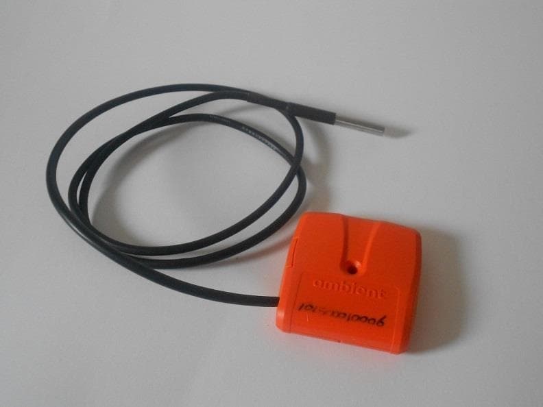
Click to zoom
Application Details
- Equipment Class
- DTS - Digital Transmission System
- Date of Grant
- Jan 05, 2014
- Application Purpose
- Original Equipment
- Date of Application
- Jan 05, 2014
- Equipment Note
- SmartPoint
- Frequency Range
- 2405.00000000 - 2480.00000000
- Company
- Ambient Systems B.V.
- Country
- Netherlands
Documents & Files
Document Text
Text extracted from the exhibit documents filed with the FCC. Open a document above to read the original.
Users Manual
Model: SP3000T Revision P1A/01102013 USER MANUAL SmartPoint SP3000T User Manual SmartPoint T Ambient Systems B.V. Page 1 of 19 Colosseum 15D • 7521 PV Enschede • The Netherlands T: +31 88 2624368 • F: +31 88 2624399 • www.ambient-systems.net KvK: 08122911 • VAT NL: 81297625381 CHECK.TRACK.TRACE. Model: SP3000T Revision P1A/01102013 USER MANUAL SmartPoint SP3000T Product Code(s): 900.100.025.003 (SP3000T), 900.100.025.005 (SP3000TH), 900.100.025.008 (SP3000TERS), 900.100.025.010 and 900.100.025.011 (SP3000T1W) Table of Contents 1Preface.......................................................................................................3 1.1What is the SmartPoint SP3000T.................................................................................3 1.2Features......................................................................................................................3 1.3Conventions................................................................................................................3 1.4Further information.....................................................................................................4 2Introduction................................................................................................5 2.1About This Manual.......................................................................................................5 Ambient Systems B.V. Page 2 of 19 Colosseum 15D • 7521 PV Enschede • The Netherlands T: +31 88 2624368 • F: +31 88 2624399 • www.ambient-systems.net KvK: 08122911 • VAT NL: 81297625381 CHECK.TRACK.TRACE. Model: SP3000T Revision P1A/01102013 USER MANUAL SmartPoint SP3000T 2.2Related Documentation...............................................................................................5 2.3Required Tools.............................................................................................................5 3Product Types..............................................................................................6 4Installation..................................................................................................7 4.1Preparation..................................................................................................................7 4.2First Time Use..............................................................................................................7 4.3Mounting.....................................................................................................................7 5Calibration..................................................................................................7 6Powering Options........................................................................................9 7LED Behavior.............................................................................................10 7.1Awaken from hibernation..........................................................................................10 7.2Rapid Response mode...............................................................................................10 7.3Normal operation......................................................................................................10 8DDI Drivers................................................................................................11 9Storage.....................................................................................................13 10Disposal..................................................................................................13 11Appendices..............................................................................................14 11.1Appendix A: Technical Support................................................................................14 Ambient Systems B.V. Page 3 of 19 Colosseum 15D • 7521 PV Enschede • The Netherlands T: +31 88 2624368 • F: +31 88 2624399 • www.ambient-systems.net KvK: 08122911 • VAT NL: 81297625381 CHECK.TRACK.TRACE. Model: SP3000T Revision P1A/01102013 USER MANUAL SmartPoint SP3000T 1Preface 1.1What is the SmartPoint SP3000T The SmartPoint(SP) SP3000T combines a high accuracy temperature sensor and extensive logging capabilities with wireless communication capabilities. Due to the devices extreme energy efficiency, it has long battery life. The SP3000T is intended for static deployment in, for example, cool cells or temperature controlled warehouses, or mobile deployment, for example, attached to temperature sensitive produce. The temperature samples are conform EN12830 (type D). Optionally, the temperature sensor of the SP3000T can be calibrated (service sold separately, including calibration certificate). The SP3000T operates inside any 3000 Series wireless network consisting of a ConnectGate(CG) or Gateway(GW) and MicroRouters(MRs). As soon as the SP3000T is activated and is in range of an infrastructure device, it will start reporting the temperature 1 at a 5 minute interval. Optionally, the SP3000T can be configured for different reporting rates and for smart alerting based on temperature measurements. Temperature measurements are stored for up to 28 days in the SP3000T. 1.2Features 1.Accurate Temperature Sensor The internal TMP102 temperature sensor ??? 2.Low Power 1 Assuming factory settings of the ESP3000T/H/CO2 and default security settings of the 3000 Series Infrastructure. Ambient Systems B.V. Page 4 of 19 Colosseum 15D • 7521 PV Enschede • The Netherlands T: +31 88 2624368 • F: +31 88 2624399 • www.ambient-systems.net KvK: 08122911 • VAT NL: 81297625381 CHECK.TRACK.TRACE. Model: SP3000T Revision P1A/01102013 USER MANUAL SmartPoint SP3000T The internal temperature sensor is best-in-class with regards to energy consumption and enables long-term battery-operated usage. 3.Long Range The SP3000T has a combined Power Amplifier (PA) & Low Noise Amplifier (LNA) offering maximum radio range. 4.Easy Installation Due to the fact that the SP3000T is powered by an internal battery, it can be configured and in…
Text truncated - open the document above for the full version.
Users Manual
FCC INFORMATION (USA): This device complies with Part 15 of the FCC Rules. Operation is subject to the following two conditions: 1. This device may not cause harmful interference, and 2. This device must accept any interference received, including interference that may cause undesired operation. Note: This equipment has been tested and found to comply with the limits for a Class B digital device, pursuant to part 15 of the FCC Rules. These limits are designed to provide reasonable protection against harmful interference in a residential installation. This equipment generates, uses and can radiate radio frequency energy and, if not installed and used in accordance with the instructions, may cause harmful interference to radio communications. However, there is no guarantee that interference will not occur in a particular installation. If this equipment does cause harmful interference to radio or television reception, which can be determined by turning the equipment off and on, the user is encouraged to try to correct the interference by one or more of the following measures: —Reorient or relocate the receiving antenna. —Increase the separation between the equipment and receiver. —Connect the equipment into an outlet on a circuit different from that to which the receiver is connected. —Consult the dealer or an experienced radio/TV technician for help. Caution: Any changes or modifications not expressly approved by the party responsible for compliance could void the user's authority to operate this equipment. IC INFORMATION (Canada): Industry Canada Statement: This device complies with RSS-210 of the Industry Canada Rules. Operation is subject to the following two conditions: 1) this device may not cause interference and 2) this device must accept any interference, including interference that may cause undesired operation of the device. IC Radiation Exposure Statement: This equipment complies with IC radiation exposure limits set forth for an uncontrolled environment. Avis d’Industrie Canada: Cet appareil est conforme à la norme CNR-210 des règlements d’Industrie Canada. Son fonctionnement est sujet aux deux conditions suivantes: 1) Cet appareil ne doit pas provoquer d’interférences et 2) Cet appareil doit accepter toutes les interférences, y compris celles pouvant entraîner son dysfonctionnement. Avis d’Industrie Canada sur l’exposition aux Rayonnements: Cet appareil est conforme aux limites d’exposition aux rayonnements d’Industrie Canada pour un environnement non contrôlé. R&TTE INFORMATION (European Union): t.b.d.
Cover Letter(s)
FCC Confidentiality Request Number: CF303 Version: V05 Date: 21-05-2012 (Permanent or also called long term confidentiality is the normal method to keep certain docuements confidential, and may apply to schematics, block diagrams, operational description and bill of materials.) To: Federal Communications Commission Equipment Authorization Branch 7435 Oakland Mills Road Columbia, MD 21046 Pursuant to 47 CFR Section 0.459(a) & (b), we, (the applicant / grantee) Company nameAmbient System B.V. AddressColosseum 15d CityEnschede CountryThe Netherlands request for this certification filing under: Grantee CodeProduct Number FCC ID:XGR-SP3000T to maintain permanent confidentiality for the following documents submitted within this application: (please cross what is applicable, or add other documents, provide the file name and description) ExhibitFile NameDescription XOperational Descriptionexplaining the functioning of the block diagram XBlock Diagramsshowing the systematic building blocks of the EUT XSchematics Diagramsshowing components, their values and interconnection Above materials crossed contain secrets, proprietary and technical information, which would customarily be guarded from competitors under 47 CFR, section 0.457(d)(2). Disclosure or publication or any portion of this company confidential material to other parties could cause substantial competitive harm and provide unjustified benefits for competitors. We understand that pursuant to 47 CFR section 0.457(d)(1)(ii) disclosure of the applicant and all accompanying documentation will not be made before the date of the grant. The documents indicated as confidential above, are not publicly available elsewhere. Attestation: City and Country:Date:Name: (this must be a person) Function:Signature: (or official company stamp) Enschede The Netherlands 2013-11-01Mark Koop (authorized) Manager
Cover Letter(s)
FCC Authorization Letter Number: CF304 Version: V03 Date: 01-08-2011 We, (the approval holder) Company nameAmbient Systems B.V. AddressColosseum 15d CityEnschede CountryThe Netherlands declare that the following representative (agent): Name (person)M. Koop Company nameTeleconformity AddressRietven 31 CityEnschede CountryThe Netherlands is hereby authorized to sign and apply the following equipment for certification on our behalf: Product DescriptionSmartPoint Type or Model(s)SP3000T, SP3000TH, SP3000T1W, SP3000TERS Tradename or Brand(s)Ambient Attestation: City and Country:Date:Name: (this must be a person) Function:Signature: (or official company stamp) Enschede The Netherlands 30 sep 2013Linda HowsonOperations Officer
External Photos
External Photographs Front SP3000T, SP3000TH, SP3000T1W and SP3000TERS:Back SP3000T, SP3000T1W and SP3000TERS: Back SP3000TH, with humidity sensor on the back:SP3000T1W, with external temperature sensor : SP3000TERS, with external reed sensor :Available color variants:
ID Label/Location Info
Label and Label Location This label is an example for model SP3000T. In total there are 4 models. Identical labels exist for the other 3 models, SP3000TH, SP3000T1W and SP3000TERS The content in the area of the blue dotted line will show either one of the 4 models. Label Location: The label is wrapped around the device positioned within the indented area XGR 8398A
Internal Photos
Internal Photographs Enclosure opened:PCB front-side SP3000T, SP3000T1W and SP3000TERS: PCB front-side SP3000T, SP3000T1W and SP3000TERS: PCB backside, identical for all models: Position of temperature sensor, for all models:PCB front-side SP3000TH, placement of humidity sensor: SP3000T1W, connection of external 1W sensor cable:SP3000TERS, connection of external Reed sensor cable:
RF Exposure Info
RF Exposure FCC ID: XGR-SP3000T IC: 8398A-SP3000T Frequency: 2405-2480 MHz (16 channels) Modulation: OQPSK Mid-Channel: 2.440 GHz Mid-Channel Peak Power, Conducted: 6.2 dBm == 4.2 mW Antenna Gain (max): G = 3.3 dBi Peak, Radiated = 6.2 dBm + 3.3 dBi = 9.5 dBm = 8.91 mW The devices are programmed in such a way, that the duty cycle is less than 5% during operation. Average, Radiated (calculated): 8.91 * 5% = 0.45 mW SAR Test Exclusion Thresholds specified in KDB447498 Appendix A: Evaluation: During operation (operational mode) this device is typically used > 20 cm from persons. The devices are only held in the hand for manual (de-)activation using a magnetic mat. The Calculated Radiated Average output power is taken as worst case, and this emission level appears to be far under the maximum allowed emission level at even the closest distance for 2.4G device specified in this table. Conclusion: The emitted power appears to be below the required limit, so PASS.
Test Report
FCC ID: XGR-SP3000T IC: 8398A-SP3000T Test Report No.: 13091904.fcc01 Page 1 of 33 Client: Ambient Systems B.V. Colosseum 15d, 7521 PV Enschede Netherlands Test Item: Digital Transmission System (DTS), SmartPoint IEEE802.15.4 based wireless sensor, measuring temperature and/or humidity, or equipped with reed contact; enclosure can be orange, yellow or white. Identification: SP3000T, SP3000TH, SP3000T1W, SP3000TERS Serial Number: -- Project No.: 13091904 Date of Receipt: September 30, 2013 Testing Location: TÜV Rheinland EPS Eiberkamp 10 9351VT Leek Test Specification: FCC 47 CFR Part 15, Subpart C, Section 15.247 (10-1-12 Edition) RSS-Gen (issue 3, December 2010) an RSS-210 (Issue 8, December 2010) ANSI C63.10:2009 KDB Publication No. 558074 D01 V3.01: Measurement of Digital Transmission Systems Operating under Section 15.247 (10/4/13) Test Result: The test item passed the test specification(s). Testing Laboratory: TÜV Rheinland EPS Eiberkamp 10 9351 VT Leek Tested by: 2013-10-09 R. van der Meer / Inspector Date Name/Position Signature Reviewed by: 2013-10-09 O. Hoekstra / Reviewer Date Name/Position Signature Other Aspects:-. Abbreviations: P(ass) = passed F(ail) = failed N/A = not applicable N/T = not tested This report shall not be reproduced, except in full, without the written permission of TÜV Rheinland EPS The test results relate only to the item(s) tested. . FCC ID: XGR-SP3000T IC: 8398A-SP3000T Test Report No.: 13091904.fcc01 Page 2 of 33 TEST SUMMARY 5.1.1 CONDUCTED MEASUREMENTS AT ANTENNA PORT RESULT: PASS 5.1.2 6DB AND 99% BANDWIDTH RESULT: PASS 5.1.3 PEAK POWER SPECTRAL DENSITY RESULT: PASS 5.1.4 BAND EDGE CONDUCTED EMISSIONS RESULT: Pass 5.1.5 RADIATED SPURIOUS EMISSIONS OF TRANSMITTER RESULT: PASS 5.1.6 RADIATED SPURIOUS EMISSIONS OF TRANSMITTER IN RESTRICTED BANDS RESULT: PASS 5.2.1 AC POWER LINE CONDUCTED EMISSION OF TRANSMITTER RESULT: PASS FCC ID: XGR-SP3000T IC: 8398A-SP3000T Test Report No.: 13091904.fcc01 Page 3 of 33 Contents 1. GENERAL REMARKS ............................................................................................... 4 1.1 COMPLEMENTARY MATERIALS ................................................................................. 4 2. TEST SITES ............................................................................................................ 4 2.1 TEST FACILITIES ..................................................................................................... 4 2.2 LIST OF TEST AND MEASUREMENT INSTRUMENTS TABLE 1: LIST OF TEST AND MEASUREMENT EQUIPMENT ..................................................................................... 5 2.3 MEASUREMENT UNCERTAINTY ................................................................................. 6 3. GENERAL PRODUCT INFORMATION ........................................................................... 7 3.1 PRODUCT FUNCTION AND INTENDED USE .................................................................. 7 3.2 SYSTEM DETAILS .................................................................................................... 7 3.3 COUNTERMEASURES TO ACHIEVE EMC COMPLIANCE ................................................ 9 4. TEST SET-UP AND OPERATION MODES ................................................................... 10 4.1 TEST METHODOLOGY ............................................................................................ 10 4.2 OPERATION MODES .............................................................................................. 10 4.3 PHYSICAL CONFIGURATION FOR TESTING ............................................................... 11 4.4 TEST SOFTWARE .................................................................................................. 12 4.5 SPECIAL ACCESSORIES AND AUXILIARY EQUIPMENT ............................................... 13 5. TEST RESULTS ..................................................................................................... 14 5.1 CONDUCTED MEASUREMENTS AT ANTENNA PORT .................................................. 14 5.1.1 Conducted Output Power ........................................................................................................... 14 5.1.2 6dB and 99% Bandwidth ............................................................................................................ 18 5.1.3 Peak Power Spectral Density .................................................................................................... 22 5.1.4 Band Edge Conducted Emissions ............................................................................................. 26 5.1.5 Radiated Spurious Emissions of Transmitter ............................................................................. 29 5.2 AC POWER LINE CONDUCTED MEASUREMENTS ...................................................... 33 5.2.1 AC Power Line Conducted Emission of Transmitter .................................................................. 33 FCC ID: XGR-SP3000T IC: 8398A-SP3000T Test Report No.: 13091904.fcc01 Page 4 of 33 1. General Remarks 1.1 Complementary Materials Appendix: Identical Equipment Declaration SP3000. 2. Test Sites 2.1 Test Facilities The Federal Communications Commission and Industry Canada has reviewed the technical characteristics of the test facilities at TÜV Rheinland EPS , located in Leek, 9351VT Eiberkamp 10, The Netherlands, and has found these test facilities to be in compliance with the requirements of 47 CFR Part 15, section 2.948. The description of the test facilities has been filed at the Office of the Federal Communications Commission under registration number 90828. The facility has been added to the list of laboratories performing these test services for the public on a fee basis. The description of the test facilities has been filed to Industry Canada under registration number 2932G-2. The facility has been added to the list of laboratories performing these test services for the public on a fee basis. Normal te…
Text truncated - open the document above for the full version.
Test Setup Photos
Testing and certification of electronic and electric appliances, systems, installations and telecommunication systems TÜV Rheinland EPS P.O. Box 37 9350 AA Leek (NL) Eiberkamp 10 9351 VT Leek (NL) Telephone: +31 594 505005 Telefax: +31 594 504804 Internet: www.tuv-eps.com E-mail: [email protected] Project number: 13091904.p03 Page 1 of 10 PHOTOGRAPHS OF THE TESTSETUP OF A DIGITAL TRANSMISSION SYSTEM, SmartPoint, BRAND Ambient MODELS SP3000T, SP3000TH, SP3000T1W, SP3000TERS 13091904.p03 October 15, 2013 FCC listed Industry Canada R&TTE, LVD, EMC Notified Body : : : : 90828 2932G-2 1856 Test specification(s): Description of EUT: Manufacturer: Brand mark: Models: FCC ID: IC: FCC Part 15, RSS-Gen, RSS-210 Digital Transmission System, SmartPoint Ambient Systems B.V. Ambient SP3000T, SP3000TH, SP3000T1W, SP3000TERS XGR-SP3000T 8398A-SP3000T Project number: 13091904.p03 Page 2 of 10 Description of test item Test item : Digital Transmission System, SmartPoint Manufacturer : Ambient Systems B.V. Brand : Ambient Model : SP3000T, SP3000TH, SP3000T1W, SP3000TERS Serial number(s) : -- FCC ID : XGR-SP3000T IC : 8398A-SP3000T Applicant information Applicant's representative : Linda Howson / Dr. Ir. Lodewijk van Hoesel Company : Ambient Systems B.V. Address : Colosseum 15d Postal code : 7521PV City : Enschede Country : Netherlands Telephone number : +31(0)882624368 Telefax number : +31(0)882624399 Email [email protected] Test specification(s): Description of EUT: Manufacturer: Brand mark: Models: FCC ID: IC: FCC Part 15, RSS-Gen, RSS-210 Digital Transmission System, SmartPoint Ambient Systems B.V. Ambient SP3000T, SP3000TH, SP3000T1W, SP3000TERS XGR-SP3000T 8398A-SP3000T Project number: 13091904.p03 Page 3 of 10 Table of contents 1 PHOTOGRAPHS OF THE TESTSETUP. ....................................................................................................................... 4 1.1 RADIATED EMISSIONS. ................................................................................................................................................... 4 1.1.1 Radiated emissions overview ............................................................................................................................ 4 1.1.2 Radiated emissions, testsetup arrangement views ........................................................................................ 6 2 CONDUCTED TESTS. ....................................................................................................................................................... 9 2.1.1 Conducted tests overview .................................................................................................................................. 9 2.1.3 Antenna port conducted tests. RF cable connected to antenna terminals................................................ 10 Test specification(s): Description of EUT: Manufacturer: Brand mark: Models: FCC ID: IC: FCC Part 15, RSS-Gen, RSS-210 Digital Transmission System, SmartPoint Ambient Systems B.V. Ambient SP3000T, SP3000TH, SP3000T1W, SP3000TERS XGR-SP3000T 8398A-SP3000T Project number: 13091904.p03 Page 4 of 10 1 Photographs of the testsetup. 1.1 Radiated Emissions. 1.1.1 Radiated emissions overview Test specification(s): Description of EUT: Manufacturer: Brand mark: Models: FCC ID: IC: FCC Part 15, RSS-Gen, RSS-210 Digital Transmission System, SmartPoint Ambient Systems B.V. Ambient SP3000T, SP3000TH, SP3000T1W, SP3000TERS XGR-SP3000T 8398A-SP3000T Project number: 13091904.p03 Page 5 of 10 Test specification(s): Description of EUT: Manufacturer: Brand mark: Models: FCC ID: IC: FCC Part 15, RSS-Gen, RSS-210 Digital Transmission System, SmartPoint Ambient Systems B.V. Ambient SP3000T, SP3000TH, SP3000T1W, SP3000TERS XGR-SP3000T 8398A-SP3000T Project number: 13091904.p03 Page 6 of 10 1.1.2 Radiated emissions, testsetup arrangement views Model SP3000TERS with Reed contacts, placed horizontal and vertical Test specification(s): Description of EUT: Manufacturer: Brand mark: Models: FCC ID: IC: FCC Part 15, RSS-Gen, RSS-210 Digital Transmission System, SmartPoint Ambient Systems B.V. Ambient SP3000T, SP3000TH, SP3000T1W, SP3000TERS XGR-SP3000T 8398A-SP3000T Project number: 13091904.p03 Page 7 of 10 Model SP3000W with external temp Test specification(s): Description of EUT: Manufacturer: Brand mark: Models: FCC ID: IC: FCC Part 15, RSS-Gen, RSS-210 Digital Transmission System, SmartPoint Ambient Systems B.V. Ambient SP3000T, SP3000TH, SP3000T1W, SP3000TERS XGR-SP3000T 8398A-SP3000T Project number: 13091904.p03 Page 8 of 10 Model SP3000TH with Hum Model SP3000T with only Temp Test specification(s): Description of EUT: Manufacturer: Brand mark: Models: FCC ID: IC: FCC Part 15, RSS-Gen, RSS-210 Digital Transmission System, SmartPoint Ambient Systems B.V. Ambient SP3000T, SP3000TH, SP3000T1W, SP3000TERS XGR-SP3000T 8398A-SP3000T Project number: 13091904.p03 Page 9 of 10 2 Conducted tests. 2.1.1 Conducted tests overview AUX EUT AUX Spectrum Analyzer AUX Power Supply for EUT AUX host for EUT software Test specification(s): Description of EUT: Manufacturer: Brand mark: Models: FCC ID: IC: FCC Part 15, RSS-Gen, RSS-210 Digital Transmission System, SmartPoint Ambient Systems B.V. Ambient SP3000T, SP3000TH, SP3000T1W, SP3000TERS XGR-SP3000T 8398A-SP3000T Project number: 13091904.p03 Page 10 of 10 2.1.3 Antenna port conducted tests. RF cable connected to antenna terminals.
Contact Information
Applicant
Lodewijk van Hoesel(CTO)
Technical Contact
Test Firm
TUV Rheinland Nederland B.V.Wiebe Boekema
Technical Specifications
| # | Rule Parts | Frequency Range | Power Output |
|---|---|---|---|
| 1 | 15C | 2.40 GHz - 2.48 GHz | 4.20 mW |
Other Applications from Ambient Systems B.V.
XGR-GW3000V2
Jun 10, 2015Gateway MicroRouter
Equipment Class
DTS - Digital Transmission System
XGR-SM3000
Dec 07, 20092.4GHz RFID Module
Equipment Class
DTS - Digital Transmission System