XKB-BAS930BPayment Terminal Base
INGENICO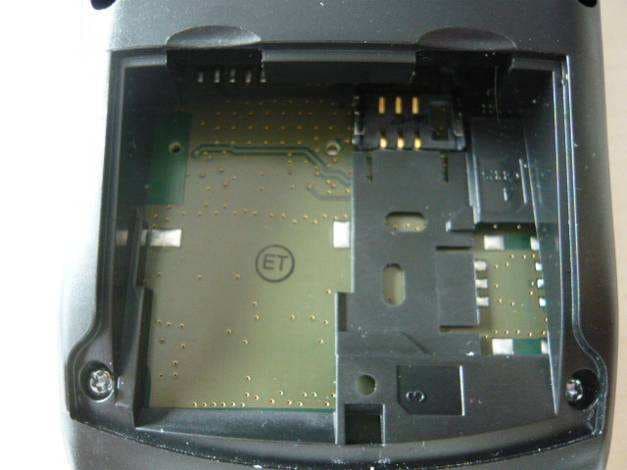
Click to zoom
Application Details
- Equipment Class
- JBP - Part 15 Class B Computing Device Peripheral
- Date of Grant
- Jul 20, 2010
- Application Purpose
- Original Equipment
- Date of Application
- Jul 19, 2010
- Equipment Note
- Payment Terminal Base
- Company
- INGENICO
- Country
- France
Documents & Files
Document Text
Text extracted from the exhibit documents filed with the FCC. Open a document above to read the original.
Users Manual
INGENICO – 192 avenue Charles de Gaulle – 92200 Neuilly sur Seine - FRANCE Tél. 33(0)1 46 25 82 00 - Fax 33 (0)1 47 72 56 95 www.ingenico.com EFT930 Wireless Series U s e r G u i d e EFT930 Wireless Series • 2/35 Copyright © 2009 Ingenico 9000001568 R11 000 02/941 All rights reserved Contents 1. Introduction___________________________________________________ 4 2. Presentation __________________________________________________ 4 2.1. Content of the box ............................................................................................ 4 2.2. Overview of the EFT930 ............................................................................................ 5 2.3. Keyboard details and functionality ...................................................................................... 6 3. Use of the terminal_____________________________________________ 6 3.1. Adjusting contrast ............................................................................................ 6 3.2. Reading card ............................................................................................ 7 3.3. Switching off the terminal ............................................................................................ 8 3.4. Installing the terminal on the base....................................................................................... 8 4. Installation ___________________________________________________ 9 4.1. Recommendations ............................................................................................ 9 4.2. Terminal connections ............................................................................................ 9 4.3. Installing Modules ...........................................................................................10 4.3.1. SAM1/SAM2 10 4.3.2. SAM3/SAM4 or SIM 10 4.3.1. MMC or SD Memory Card 11 4.4. Paper roll ........................................................................................... 12 4.4.1. Mains characteristics of INGENICO paper roll 12 4.4.1. Installing paper roll 12 4.5. Battery ...........................................................................................14 4.5.1. Main characteristics 14 4.5.2. Installing the battery 14 4.5.3. Charging the battery 14 4.5.4. Changing the battery 16 5. Base _________________________________________________________17 5.1. Base identification ........................................................................................... 17 5.1.1. Base charger (EFT930G or EFT930W) 17 5.1.2. Base Modem 18 5.1.3. Base Ethernet (EFT930P) 20 5.1.4. Base Bluetooth Modem 21 5.1.5. Base Bluetooth Ethernet (EFT930B) 23 5.1.6. Base Bluetooth Ethernet Modem (EFT930B) 24 5.1.6.1. Overview 24 5.1.6.2. USB/RS232 Cable for Base BEM 25 5.1.7. Base Ethernet Modem (EFT930P) 26 5.1.7.1. Overview 26 5.1.7.2. USB/RS232 Cable for Base EM 27 6. Recommendations ___________________________________________ 28 6.1. Safety .......................................................................................... 28 6.2. Telephone call .......................................................................................... 29 7. Standards ___________________________________________________ 30 8. Troubleshooting______________________________________________ 34 9. Annex ______________________________________________________ 35 This symbol indicates an important Warning. This symbol indicates a piece of Advice. 1. Introduction We hope that you will be fully satisfied with your new terminal EFT930. This terminal comes in different models: EFT930G, EFT930B, EFT930P, EFT930W. Please read this guide to understand and make the best use of your terminal. It presents you the necessary information about use, installation, maintenance, safety and security recommendations. WARRANTY / SECURITY Use only the power supply included with the product to ensure best performance and safety. Maintenance should only be provided by Ingenico authorized technician. Failure to comply with these instructions will void the manufacturer’s responsibility. 2. Presentation 2.1. Content of the box WARNING The power supply unit provided with your equipment is specially designed for Ingenico terminals. Do not use any other power supply. The use of a power supply with apparently similar voltage/current characteristics may damage your terminal. ADVICE : Keep the packaging. It must be re-used whenever the terminal is shipped. EFT930 terminal unit equipped with a paper roll A power supply unit that connects the power supply to the electric network A base receiving the unit (if no power travel adapter) A user guide A battery pack disconnected A telephone cable (With base modem) Power travel adapter (When no base) Or 2.2. Overview of the EFT930 Terminal Base Weight About 120g Dimensions 153 x 87 x 33 mm (L x w x h) Power supply unit Weight About 100g 2pole sockets 1 A The power supply unit is specially fitted for INGENICO terminals. Weight Between 360 g and 410 g, according to the model without paper roll and battery Dimensions 180 x 79 x 57 mm (L x w x h) Electrical mains network 100-240VAC / 50-60 Hz - Class II equipment Mini USB A serial link 100 mA max Connections on terminal Mini USB B serial link 1 st Smart card reader Base unit Backlit keyboard Magnetic card reader Compartment where are located : • the battery pack • the modules SAM1/ SAM2 Large graphic display Easy loading printer Compartment where are located : • the modules SAM3/SAM4 or SIM • the modules MMC or SDCARD • the 2 nd Smart card reader 2.3. Keyboard details and functionality This chapter describes the key functions of a terminal with no specific application. Some keys can have other functions according to the applications that are in the terminal. 3. Use of the terminal ADVICE Before to use the terminal, always check if the roll of paper is present. 3.1. Adjusting contrast If you wish to increase or to decrease the contrast of the characters displayed on screen, press simultaneously a…
Text truncated - open the document above for the full version.
Users Manual
INGENICO – 192 avenue Charles de Gaulle – 92200 Neuilly sur Seine - FRANCE Tél. 33(0)1 46 25 82 00 - Fax 33 (0)1 47 72 56 95 www.ingenico.com EFT930 Wireless Series U s e r G u i d e EFT930 Wireless Series • 2/35 Copyright © 2009 Ingenico 9000001568 R11 000 02/941 All rights reserved Contents 1. Introduction___________________________________________________ 4 2. Presentation __________________________________________________ 4 2.1. Content of the box ............................................................................................ 4 2.2. Overview of the EFT930 ............................................................................................ 5 2.3. Keyboard details and functionality ...................................................................................... 6 3. Use of the terminal_____________________________________________ 6 3.1. Adjusting contrast ............................................................................................ 6 3.2. Reading card ............................................................................................ 7 3.3. Switching off the terminal ............................................................................................ 8 3.4. Installing the terminal on the base....................................................................................... 8 4. Installation ___________________________________________________ 9 4.1. Recommendations ............................................................................................ 9 4.2. Terminal connections ............................................................................................ 9 4.3. Installing Modules ...........................................................................................10 4.3.1. SAM1/SAM2 10 4.3.2. SAM3/SAM4 or SIM 10 4.3.1. MMC or SD Memory Card 11 4.4. Paper roll ........................................................................................... 12 4.4.1. Mains characteristics of INGENICO paper roll 12 4.4.1. Installing paper roll 12 4.5. Battery ...........................................................................................14 4.5.1. Main characteristics 14 4.5.2. Installing the battery 14 4.5.3. Charging the battery 14 4.5.4. Changing the battery 16 5. Base _________________________________________________________17 5.1. Base identification ........................................................................................... 17 5.1.1. Base charger (EFT930G or EFT930W) 17 5.1.2. Base Modem 18 5.1.3. Base Ethernet (EFT930P) 20 5.1.4. Base Bluetooth Modem 21 5.1.5. Base Bluetooth Ethernet (EFT930B) 23 5.1.6. Base Bluetooth Ethernet Modem (EFT930B) 24 5.1.6.1. Overview 24 5.1.6.2. USB/RS232 Cable for Base BEM 25 5.1.7. Base Ethernet Modem (EFT930P) 26 5.1.7.1. Overview 26 5.1.7.2. USB/RS232 Cable for Base EM 27 6. Recommendations ___________________________________________ 28 6.1. Safety .......................................................................................... 28 6.2. Telephone call .......................................................................................... 29 7. Standards ___________________________________________________ 30 8. Troubleshooting______________________________________________ 34 9. Annex ______________________________________________________ 35 This symbol indicates an important Warning. This symbol indicates a piece of Advice. 1. Introduction We hope that you will be fully satisfied with your new terminal EFT930. This terminal comes in different models: EFT930G, EFT930B, EFT930P, EFT930W. Please read this guide to understand and make the best use of your terminal. It presents you the necessary information about use, installation, maintenance, safety and security recommendations. WARRANTY / SECURITY Use only the power supply included with the product to ensure best performance and safety. Maintenance should only be provided by Ingenico authorized technician. Failure to comply with these instructions will void the manufacturer’s responsibility. 2. Presentation 2.1. Content of the box WARNING The power supply unit provided with your equipment is specially designed for Ingenico terminals. Do not use any other power supply. The use of a power supply with apparently similar voltage/current characteristics may damage your terminal. ADVICE : Keep the packaging. It must be re-used whenever the terminal is shipped. EFT930 terminal unit equipped with a paper roll A power supply unit that connects the power supply to the electric network A base receiving the unit (if no power travel adapter) A user guide A battery pack disconnected A telephone cable (With base modem) Power travel adapter (When no base) Or 2.2. Overview of the EFT930 Terminal Base Weight About 120g Dimensions 153 x 87 x 33 mm (L x w x h) Power supply unit Weight About 100g 2pole sockets 1 A The power supply unit is specially fitted for INGENICO terminals. Weight Between 360 g and 410 g, according to the model without paper roll and battery Dimensions 180 x 79 x 57 mm (L x w x h) Electrical mains network 100-240VAC / 50-60 Hz - Class II equipment Mini USB A serial link 100 mA max Connections on terminal Mini USB B serial link 1 st Smart card reader Base unit Backlit keyboard Magnetic card reader Compartment where are located : • the battery pack • the modules SAM1/ SAM2 Large graphic display Easy loading printer Compartment where are located : • the modules SAM3/SAM4 or SIM • the modules MMC or SDCARD • the 2 nd Smart card reader 2.3. Keyboard details and functionality This chapter describes the key functions of a terminal with no specific application. Some keys can have other functions according to the applications that are in the terminal. 3. Use of the terminal ADVICE Before to use the terminal, always check if the roll of paper is present. 3.1. Adjusting contrast If you wish to increase or to decrease the contrast of the characters displayed on screen, press simultaneously a…
Text truncated - open the document above for the full version.
External Photos
FCC ID: XKB-EFT930B Page 1/5 EXTERNAL PHOTOS OF TESTED EUT General views of Power supply FRIWO General views of Power supply PHIHONG FCC ID: XKB-EFT930B Page 2/5 General views of Base General views of MagicBox FCC ID: XKB-EFT930B Page 3/5 General views of Terminal on Base with MagicBox General views of Terminal EFT930G FCC ID: XKB-EFT930B Page 4/5 General view of printer Back views with and without cover FCC ID: XKB-EFT930B Page 5/5 Detail views without cover
External Photos
FCC ID: XKB-EFT930B Page 1/5 EXTERNAL PHOTOS OF TESTED EUT General views of Power supply FRIWO General views of Power supply PHIHONG FCC ID: XKB-EFT930B Page 2/5 General views of Base General views of MagicBox FCC ID: XKB-EFT930B Page 3/5 General views of Terminal on Base with MagicBox General views of Terminal EFT930G FCC ID: XKB-EFT930B Page 4/5 General view of printer Back views with and without cover FCC ID: XKB-EFT930B Page 5/5 Detail views without cover
ID Label/Location Info
FCC ID: XKB-EFT930B FCC ID: XKB-BAS930B Page 1/3 PRODUCT LABELING FCC ID / IC number label Terminal Base Note: - No special tools are required to open the battery compartment. - Device is shipped without batteries FCC ID: XKB-EFT930B FCC ID: XKB-BAS930B Page 2/3 For terminal : For base : FCC ID: XKB-EFT930B FCC ID: XKB-BAS930B Page 3/3 PRODUCT REFERENCE DEFINITION EFT930G – wxyz0102 w: Magnetic Head type 1: ISO2 Reader (1 track) 2: ISO1 and ISO2 Reader (2 tracks) 3: ISO1, ISO2 and ISO3 Reader (3 tracks) 4: ISO2 and ISO3 Reader (2 tracks) x: USB Port configuration N: No USB Port A: 1 x USB Type A only B: 1 x USB Type B only C: 1 x USB Type A and 1 x USB Type B y: Extension Board Option N: With SDCARD and SAM3 L: Without X: others memory card (SAM, SDCARD) configuration z: Thermal Pinter Option H: High speed printer OK L: Low speed printer 0102: Hardware version BAS930X – wxy101 X: Link Type N: Charger Only P: Infra Red w: Serial link N: None 1: 1 serial link 2: 2 serial links x: USB Port configuration N : No USB Port A: 1 x USB Type A only B: 1 x USB Type B only C: 1 x USB Type A and 1 x USB Type B y: Network type N: None T: Telefone E: Ethernet 101: Hardware version
ID Label/Location Info
FCC ID: XKB-EFT930B FCC ID: XKB-BAS930B Page 1/3 PRODUCT LABELING FCC ID / IC number label Terminal Base Note: - No special tools are required to open the battery compartment. - Device is shipped without batteries FCC ID: XKB-EFT930B FCC ID: XKB-BAS930B Page 2/3 For terminal : For base : FCC ID: XKB-EFT930B FCC ID: XKB-BAS930B Page 3/3 PRODUCT REFERENCE DEFINITION EFT930G – wxyz0102 w: Magnetic Head type 1: ISO2 Reader (1 track) 2: ISO1 and ISO2 Reader (2 tracks) 3: ISO1, ISO2 and ISO3 Reader (3 tracks) 4: ISO2 and ISO3 Reader (2 tracks) x: USB Port configuration N: No USB Port A: 1 x USB Type A only B: 1 x USB Type B only C: 1 x USB Type A and 1 x USB Type B y: Extension Board Option N: With SDCARD and SAM3 L: Without X: others memory card (SAM, SDCARD) configuration z: Thermal Pinter Option H: High speed printer OK L: Low speed printer 0102: Hardware version BAS930X – wxy101 X: Link Type N: Charger Only P: Infra Red w: Serial link N: None 1: 1 serial link 2: 2 serial links x: USB Port configuration N : No USB Port A: 1 x USB Type A only B: 1 x USB Type B only C: 1 x USB Type A and 1 x USB Type B y: Network type N: None T: Telefone E: Ethernet 101: Hardware version
Internal Photos
FCC ID: XKB-EFT930B Page 1/13 INTERNAL PHOTOS OF TESTED EUT General Views of PCB Base FCC ID: XKB-EFT930B Page 2/13 Detail Views of PCB Base FCC ID: XKB-EFT930B Page 3/13 Detail Views of PCB Base FCC ID: XKB-EFT930B Page 4/13 General views internal of Terminal FCC ID: XKB-EFT930B Page 5/13 General views PCB of terminal FCC ID: XKB-EFT930B Page 6/13 Detail view of 13.56MHz antenna Detail views Bluetooth antenna and connector with magnetic reader FCC ID: XKB-EFT930B Page 7/13 Detail views PCB FCC ID: XKB-EFT930B Page 8/13 Detail views PCB FCC ID: XKB-EFT930B Page 9/13 Detail views PCB FCC ID: XKB-EFT930B Page 10/13 Detail views PCB FCC ID: XKB-EFT930B Page 11/13 Detail views PCB FCC ID: XKB-EFT930B Page 12/13 Detail views PCB FCC ID: XKB-EFT930B Page 13/13 Detail views of monitor Detail views of PCB printer with SAMs
Internal Photos
FCC ID: XKB-EFT930B Page 1/13 INTERNAL PHOTOS OF TESTED EUT General Views of PCB Base FCC ID: XKB-EFT930B Page 2/13 Detail Views of PCB Base FCC ID: XKB-EFT930B Page 3/13 Detail Views of PCB Base FCC ID: XKB-EFT930B Page 4/13 General views internal of Terminal FCC ID: XKB-EFT930B Page 5/13 General views PCB of terminal FCC ID: XKB-EFT930B Page 6/13 Detail view of 13.56MHz antenna Detail views Bluetooth antenna and connector with magnetic reader FCC ID: XKB-EFT930B Page 7/13 Detail views PCB FCC ID: XKB-EFT930B Page 8/13 Detail views PCB FCC ID: XKB-EFT930B Page 9/13 Detail views PCB FCC ID: XKB-EFT930B Page 10/13 Detail views PCB FCC ID: XKB-EFT930B Page 11/13 Detail views PCB FCC ID: XKB-EFT930B Page 12/13 Detail views PCB FCC ID: XKB-EFT930B Page 13/13 Detail views of monitor Detail views of PCB printer with SAMs
RF Exposure Info
FCC ID: XKB-BAS930B – Base Unit Device is a Base Unit for a Handheld Terminal (FCC ID: XKB-EFT930B). They operate as a system. Although the base qualifies as a mobile (d>20cm from body), it will be evaluated against portable exposure limits for worst case purposes. The Base Unit has a Bluetooth radio. Base Unit Bluetooth radio power level = 10.9mW EIRP. Bluetooth radio low threshold = 60 / 2.48 = 24.19 mW Since the EIRP is lower than the low threshold, device complies with FCC RF radiation exposure limits as a portable device. Collocation with the Handheld Terminal FCC ID: XKB-EFT930B The Base Unit can be collocated with the Handheld Terminal during charging mode. The Handheld Terminal has 2 radios: - Radio 1: Bluetooth - Radio 2: 13.56MHz RFID tag reader Background When all co-located transmitters are built-in or operating as an integral part of the host product and there is NO provision for external antenna connections, Determine the aggregate output power ratio of all transmitters according to Σ ΣΣ Σ [P(n) / T(n)], where P(n) is the higher of the 1. Maximum Source-Based Time-Averaged EIRP or 2. Maximum Source-Based Time-Averaged Conducted Output Power for the individual transmitter T(n) is the applicable low/high threshold with respect to the low threshold: except when routine SAR evaluation is required, SAR evaluation is not needed when Σ ΣΣ Σ[P(n)/T(n)] ≤ ≤≤ ≤ 1. T(n) = 60/f(GHz) in mW for general population. (Portable exposure category d < 2.5cm) T(1) = Handheld Unit Bluetooth radio low threshold T(1) = 60 / 2.48 = 24.19 mW T(2) = Handheld Unit 13.56MHz radio low threshold T(2) = 60 / 0.01356 = 4424.77 mW T(3) = Base Unit Bluetooth radio low threshold T(3) = 60 / 2.48 = 24.19 mW P(1) = Handheld Unit Bluetooth power Conducted = 5.6dBm Antenna Gain = 1.6dBi EIRP = 5.25mW; P(1) = 5.25mW P(2) = Handheld Unit 13.56MHz radio power EIRP = 0.03mW ; P(2) = 0.03mW P(3) = Base Unit Bluetooth radio power level P(3) = 10.9mW EIRP { P(1) / T(1) } + { P(2) / T(2) } + { P(3) / T(3) } = 0.217 + 0.000007 + 0.4504 = 0.6674 < 1 Therefore; when the Base Unit is collocated with the Handheld Terminal, as a system they comply with FCC RF radiation exposure limits as well.
RF Exposure Info
FCC ID: XKB-BAS930B – Base Unit Device is a Base Unit for a Handheld Terminal (FCC ID: XKB-EFT930B). They operate as a system. Although the base qualifies as a mobile (d>20cm from body), it will be evaluated against portable exposure limits for worst case purposes. The Base Unit has a Bluetooth radio. Base Unit Bluetooth radio power level = 10.9mW EIRP. Bluetooth radio low threshold = 60 / 2.48 = 24.19 mW Since the EIRP is lower than the low threshold, device complies with FCC RF radiation exposure limits as a portable device. Collocation with the Handheld Terminal FCC ID: XKB-EFT930B The Base Unit can be collocated with the Handheld Terminal during charging mode. The Handheld Terminal has 2 radios: - Radio 1: Bluetooth - Radio 2: 13.56MHz RFID tag reader Background When all co-located transmitters are built-in or operating as an integral part of the host product and there is NO provision for external antenna connections, Determine the aggregate output power ratio of all transmitters according to Σ ΣΣ Σ [P(n) / T(n)], where P(n) is the higher of the 1. Maximum Source-Based Time-Averaged EIRP or 2. Maximum Source-Based Time-Averaged Conducted Output Power for the individual transmitter T(n) is the applicable low/high threshold with respect to the low threshold: except when routine SAR evaluation is required, SAR evaluation is not needed when Σ ΣΣ Σ[P(n)/T(n)] ≤ ≤≤ ≤ 1. T(n) = 60/f(GHz) in mW for general population. (Portable exposure category d < 2.5cm) T(1) = Handheld Unit Bluetooth radio low threshold T(1) = 60 / 2.48 = 24.19 mW T(2) = Handheld Unit 13.56MHz radio low threshold T(2) = 60 / 0.01356 = 4424.77 mW T(3) = Base Unit Bluetooth radio low threshold T(3) = 60 / 2.48 = 24.19 mW P(1) = Handheld Unit Bluetooth power Conducted = 5.6dBm Antenna Gain = 1.6dBi EIRP = 5.25mW; P(1) = 5.25mW P(2) = Handheld Unit 13.56MHz radio power EIRP = 0.03mW ; P(2) = 0.03mW P(3) = Base Unit Bluetooth radio power level P(3) = 10.9mW EIRP { P(1) / T(1) } + { P(2) / T(2) } + { P(3) / T(3) } = 0.217 + 0.000007 + 0.4504 = 0.6674 < 1 Therefore; when the Base Unit is collocated with the Handheld Terminal, as a system they comply with FCC RF radiation exposure limits as well.
Test Report
Rapport d’essai / Test report N° 201002-6070CR-A1-R2-E JDE : 99678 DELIVRE A / ISSUED TO : INGENICO 1, Rue Claude Chappe BP 348 07503 GUILHERAND-GRANGES - France Objet / Subject : Essais de compatibilité électromagnétique conformément aux normes FCC CFR 47 Part 15, Subpart B et C. Electromagnetic compatibility tests according to the standards FCC CFR 47 Part 15, Subpart B and C Matériel testé / Apparatus under test : • Produit / Product : Lecteur carte bancaire Sans Contact / Bank payment terminal Contactless • Marque / Trade mark : INGENICO • Constructeur / Manufacturer : INGENICO • Type / Model : EFT930B-wxyz0102+BAS930X-wxy202 • Type sous test / Model under test : EFT930B-3CXH0102+BAS930B-2BB202 • N° de série / serial number : 10077PT60458108+10085PT60476288 • FCC ID : XKB-EFT930B Date des essais / Test date : Du 3 Mai au 8 Juin 2010 / From May 3 rd to June 8 th , 2010 Lieu d’essai / Test location : BUREAU VERITAS LCIE SUD-EST ZI Centr’Alp – 170 rue de Chatagnon 38430 MOIRANS - France Test réalisé par / Test performed by : Anthony MERLIN Ce document comporte /Composition of document : 43 pages. M OIRANS, LE 12 JUILLET 2010 / JULY 12TH, 2010 Ecrit par / Written by, Approuvé par / Approved by, Anthony MERLIN Jacques LORQUIN La reproduction de ce document n'est autorisée que sous sa forme intégrale. Toute reproduction partielle ou toute insertion de résultats dans un texte d'accompagnement en vue de leur diffusion doit recevoir un accord préalable et formel du LCIE. Ce document résulte d’essais effectués sur un spécimen, un échantillon ou une éprouvette. Il ne préjuge pas de la conformité de l’ensemble des produits fabriqués à l’objet essayé. Sauf indication contraire, la décision de conformité prend en compte l’incertitude de mesures. Il ne préjuge en aucun cas d’une décision de certification. This document shall not be reproduced, except in full, without t he written approval of the LCIE. This document contains results related only to the item tested. It does not imply the conformity of the whole production to the item tested .Unless otherwise specified; the decision of conformity takes into account the uncertainty of measures. This document does not anticipate any certification decision. . RAPPORT D'ESSAI / TEST REPORT N° 201002-6070CR-A1-R2-E Page : 2 / 43 SUMMARY 1. TEST PROGRAM ................................................................................................................................... 3 2. SYSTEM TEST CONFIGURATION ........................................................................................................ 4 3. RADIATED EMISSION DATA ................................................................................................................. 7 4. MAXIMUM PEAK OUTPUT POWER (15.247) ...................................................................................... 13 5. HOPPING CHANNEL SEPARATION (15.247)...................................................................................... 18 6. NUMBER OF HOPPING FREQUENCIES (15.247)............................................................................... 27 7. TIME OF OCCUPANCY (DWELL TIME) (15.247)................................................................................. 32 8. BAND EDGE MEASUREMENT (15.247) .............................................................................................. 35 9. TEST EQUIPMENT LIST (MOIRANS SITE) ......................................................................................... 42 10. UNCERTAINTIES CHART ................................................................................................................ 43 RAPPORT D'ESSAI / TEST REPORT N° 201002-6070CR-A1-R2-E Page : 3 / 43 1. TEST PROGRAM Standard: - FCC Part 15, Subpart C 15.247 - ANSI C63.4 (2009) EMISSION TEST LIMITS RESULTS (Comments) Frequency Quasi-peak value (dBμV) Average value (dBμV) 150-500kHz 66 to 56 56 to 46 0.5-5MHz 56 46 Limits for conducted disturbance at mains ports 150kHz-30MHz 5-30MHz 60 50 See report 201002-6070CR-A1-R1-E* 2 Radiated emissions 9kHz-30MHz Measure at 300m 9kHz-490kHz : 67.6dBμV/m /F(kHz) Measure at 30m 490kHz-1.705MHz : 87.6dBμV/m /F(kHz) 1.705MHz-30MHz : 29.5 dBμV/m See report 201002-6070CR-A1-R1-E* 2 Radiated emissions 30MHz-25GHz* Measure at 3m 30MHz-88MHz : 40 dBμV/m 88MHz-216MHz : 43.5 dBμV/m 216MHz-960MHz : 46.0 dBμV/m Above 960MHz : 54.0 dBμV/m PASS And see report 201002-6070CR-A1-R1-E* 2 Maximum Peak Output Power 15.247 (b) Limit: 21dBm Conducted or Radiated measurement PASS Hopping Channel Separation 15.247 (a) (1) Minimum between: Two-third 20dB Bandwidth or 25kHz Whichever is greater PASS Number of Hopping Frequencies 15.247 (a) (1) (iii) At least 15 channels used PASS Time of Occupancy (Dwell Time) 15.247 (a) (1) (iii) Maximum 0.4 sec within 31.6sec PASS Band Edge Measurement 15.247 (d) Limit: -20dBc PASS *§15.33: The highest internal source of a testing device is defined like more the highest frequency generated or used in the testing device or on which the testing device works or agrees. - If the highest frequency of the internal sources of the testing device is lower than 108 MHz, measurement must be only performed until 1GHz. - If the highest frequency of the internal sources of the testing device ranges between 108 MHz and 500 MHz, measurement must be only performed until 2GHz. - If the highest frequency of the internal sources of the testing device ranges between 500 MHz and 1 GHz, measurement must be only performed until 5GHz. If the highest frequency of the internal sources of the testing device is above 1 GHz, measurement must be only performed until 5 times the highest frequency or 40 GHz, while taking smallest of both. * 2 : In report 201002-6070CR-A1-R1-E, tests are performed with Bluetooth module activated in typical use but the equipment is been considered with a RFID 13.56MHz module and so tested in compliance with 15.225. Complementary tests of 15.247 are performed in this test report. RAPPORT D'ESSAI…
Text truncated - open the document above for the full version.
Test Report
Rapport d’essai / Test report N° 201002-6070CR-A1-R2-E JDE : 99678 DELIVRE A / ISSUED TO : INGENICO 1, Rue Claude Chappe BP 348 07503 GUILHERAND-GRANGES - France Objet / Subject : Essais de compatibilité électromagnétique conformément aux normes FCC CFR 47 Part 15, Subpart B et C. Electromagnetic compatibility tests according to the standards FCC CFR 47 Part 15, Subpart B and C Matériel testé / Apparatus under test : • Produit / Product : Lecteur carte bancaire Sans Contact / Bank payment terminal Contactless • Marque / Trade mark : INGENICO • Constructeur / Manufacturer : INGENICO • Type / Model : EFT930B-wxyz0102+BAS930X-wxy202 • Type sous test / Model under test : EFT930B-3CXH0102+BAS930B-2BB202 • N° de série / serial number : 10077PT60458108+10085PT60476288 • FCC ID : XKB-EFT930B Date des essais / Test date : Du 3 Mai au 8 Juin 2010 / From May 3 rd to June 8 th , 2010 Lieu d’essai / Test location : BUREAU VERITAS LCIE SUD-EST ZI Centr’Alp – 170 rue de Chatagnon 38430 MOIRANS - France Test réalisé par / Test performed by : Anthony MERLIN Ce document comporte /Composition of document : 43 pages. M OIRANS, LE 12 JUILLET 2010 / JULY 12TH, 2010 Ecrit par / Written by, Approuvé par / Approved by, Anthony MERLIN Jacques LORQUIN La reproduction de ce document n'est autorisée que sous sa forme intégrale. Toute reproduction partielle ou toute insertion de résultats dans un texte d'accompagnement en vue de leur diffusion doit recevoir un accord préalable et formel du LCIE. Ce document résulte d’essais effectués sur un spécimen, un échantillon ou une éprouvette. Il ne préjuge pas de la conformité de l’ensemble des produits fabriqués à l’objet essayé. Sauf indication contraire, la décision de conformité prend en compte l’incertitude de mesures. Il ne préjuge en aucun cas d’une décision de certification. This document shall not be reproduced, except in full, without t he written approval of the LCIE. This document contains results related only to the item tested. It does not imply the conformity of the whole production to the item tested .Unless otherwise specified; the decision of conformity takes into account the uncertainty of measures. This document does not anticipate any certification decision. . RAPPORT D'ESSAI / TEST REPORT N° 201002-6070CR-A1-R2-E Page : 2 / 43 SUMMARY 1. TEST PROGRAM ................................................................................................................................... 3 2. SYSTEM TEST CONFIGURATION ........................................................................................................ 4 3. RADIATED EMISSION DATA .................................................…
Text truncated - open the document above for the full version.
Contact Information
Applicant
Nicolas Jacquemont(Certification Manager)
Test Firm
LCIE Sud-EstJacques Lorquin
Technical Specifications
| # | Rule Parts | Frequency Range | Power Output |
|---|---|---|---|
| 1 | 15B | - | - |
Other Applications from INGENICO
XKB-DX8AM
Aug 06, 2026Smart POS Terminal
Equipment Class
PCB - PCS Licensed TransmitterXKB-INGA02WF
Apr 03, 2026Smart Module
Equipment Class
DSS - Part 15 Spread Spectrum TransmitterXKB-INGA02WU
Mar 25, 2026Smart Module
Equipment Class
DTS - Digital Transmission SystemXKB-MOBEM3TOC
Dec 24, 2025Mobile Payment Terminal
Equipment Class
DXX - Part 15 Low Power Communication Device Transmitter
XKB-RX9CLWBT
Aug 26, 2024Payment terminal
Equipment Class
NII - Unlicensed National Information Infrastructure TX