XKB-IMP3XXPayment Terminal
INGENICO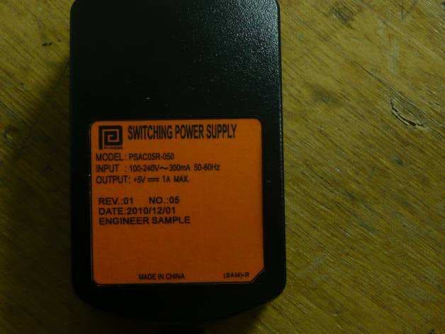
Click to zoom
Application Details
- Equipment Class
- JBP - Part 15 Class B Computing Device Peripheral
- Date of Grant
- Apr 04, 2011
- Application Purpose
- Original Equipment
- Date of Application
- Apr 04, 2011
- Equipment Note
- Payment Terminal
- Company
- INGENICO
- Country
- France
Documents & Files
Document Text
Text extracted from the exhibit documents filed with the FCC. Open a document above to read the original.
Users Manual
Ingenico – 190-192 Avenue Charles de Gaulle 92200 Neuilly sur Seine Tél. 33(0)1 46 25 82 00 - Fax 33 (0)1 47 72 56 95 iMP 3xx U s e r G u i d e iMP 3xx • 2/20 Copyright © 2010 Ingenico 900004435 R11 000 02 All rights reserved Contents 1. Introduction __________________________________________________ 4 2. Unpacking ___________________________________________________ 5 3. Recommendations_____________________________________________ 6 3.1. Security _____________________________________________________________6 3.2. Security of your terminal _______________________________________________6 3.3. EC standard compliance marking_________________________________________7 3.4. FCC & IC Compliance. __________________________________________________7 3.5. Main Characteristics ___________________________________________________9 4. Installation and connection _____________________________________10 4.1. Functional description ________________________________________________ 10 4.2. Battery insertion _____________________________________________________ 10 4.3. iPhone 4 insertion ____________________________________________________ 11 4.4. Charging iMP3XX_____________________________________________________ 12 4.5. Positioning the terminal _______________________________________________ 13 4.6. Power on / off _______________________________________________________ 13 4.7. Connection _________________________________________________________ 13 4.7.1. USB cable connection___________________________________________________________13 4.7.2. Cable disconnection___________________________________________________________ 14 4.7.3. Cradle insertion ______________________________________________________________ 14 5. Daily use _____________________________________________________15 5.1. Getting started with iMP3xx____________________________________________ 15 5.2. Keypad functions ____________________________________________________ 15 5.3. Adjusting the contrast ________________________________________________ 15 5.4. Barcode reader ______________________________________________________ 16 5.5. Card insertion _______________________________________________________ 16 5.5.1. Swiping a card________________________________________________________________ 16 5.5.2. Inserting a chip card ____________________________________________________________17 5.5.3. Reading Contactless (Optional) ___________________________________________________17 iMP 3xx • 3/20 Copyright © 2010 Ingenico 900004435 R11 000 02 All rights reserved 6. Maintenance _________________________________________________18 Cleaning of the terminal___________________________________________________ 18 6.1. Transport and storage ________________________________________________ 18 6.2. Troubleshooting _____________________________________________________ 18 6.3. End of life___________________________________________________________ 19 iMP 3xx • 4/20 Copyright © 2010 Ingenico 900004435 R11 000 02 All rights reserved 1. Introduction Thank you for choosing a payment terminal Ingenico. We recommend you to read carefully this installation guide: It gives you the necessary information about safety precautions, unpacking, installation, and maintenance of your terminal. WARRANTY / SECURITY To benefit from the guarantee-related product, and to respect the security, we ask you to use only accessories delivered in box with the product, entrusting maintenance operations only to an authorized person. The iMP3xx is battery powered, use only Ingenico parts for replacement: The iMP3xx can be powered by different sources please respect these recommendations: iMP3xx can be USB powered; it must be connected to a full compatible USB link. iMP3xx can be powered using the cradle accessory. Failure to comply with these instructions will void the manufacturer’s responsibility. This symbol indicates an important Warning. This symbol indicates a piece of advice. iMP 3xx • 5/20 Copyright © 2010 Ingenico 900004435 R11 000 02 All rights reserved 2. Unpacking ADVICE Carefully preserve the packaging of the IMP3XX. It must be re-used whenever the terminal is shipped. According to the model, the following items are included in the IMP3XX box (including optional accessories): • The IMP3XX terminal • A battery pack • This installation guide • A PSU for battery charging • The IMP3X0 cradle (optional) with PSU • The USB connection cable (optional) • The application user guide (optional) WARNING The power supply unit provided with your equipment is specially designed for Ingenico terminals. Do not use any other power supply. The use of a power supply with apparently similar voltage/current characteristics may damage your terminal. iMP 3xx • 6/20 Copyright © 2010 Ingenico 900004435 R11 000 02 All rights reserved 3. Recommendations 3.1. Security Lithium battery The IMP3XX is fitted with a lithium battery which is not accessible to the user. Only a qualified technician may be authorized to open the unit and change this component. Battery IMP3XX is fitted with battery specially designed for this terminal. • Only use the appropriate chargers and batteries listed in the Ingenico’s catalogue. • Do not short-circuit the battery. • Do not attempt to open the battery container. • Used batteries must be disposed of at the appropriates sites. Warning Risk of explosion if battery is replaced by an incorrect type, do not disassemble, use specified charger only, do not short-circuit, do not dispose of in fire, do not throw in water, dispose of used batteries according to the instructions. 3.2. Security of your terminal Upon receipt of your terminal you should check for signs of tampering of the equipment. It is strongly advised that these checks are performed regularly after receipt. You should check, for example: that the keypad is firmly in place; that there is no evidence of unusual wires that have been connected to any ports on your terminal or associated equipment, the chip card reader, or any other…
Text truncated - open the document above for the full version.
External Photos
FCC ID: XKB-IMP3XX Page 1/2 EXTERNAL PHOTOS OF TESTED EUT Only plug change between US version and Multiplug version General views of Battery pack FCC ID: XKB-IMP3XX Page 2/2 General views (Difference between version with or without barcode reader)
ID Label/Location Info
FCC ID: XKB-IMP3XX Page 1/2 PRODUCT LABELING FCC ID / IC number label MATERIAL : Color: White RAL9010 Adhésive one side: permanent UL969 certified Material: Vynil or Polyester, thickness 50 to 100μm UL969 certified MARKING : BLACK RAL 9005 must be respect UL969 FONT : ARIAL FCC ID: XKB-IMP3XX Page 2/2 Localization of label: Note: - No special tools are required to open the battery compartment. - Device is shipped without battery plugged
Internal Photos
FCC ID: XKB-IMP3XX Page 1/7 INTERNAL PHOTOS OF TESTED EUT General views of enclosure FCC ID: XKB-IMP3XX Page 2/7 FCC ID: XKB-IMP3XX Page 3/7 Views of Iphone dock Views of barcode button FCC ID: XKB-IMP3XX Page 4/7 Views of magnetic card Views of PCB FCC ID: XKB-IMP3XX Page 5/7 Detail views of screener FCC ID: XKB-IMP3XX Page 6/7 Detail views of PCB FCC ID: XKB-IMP3XX Page 7/7 Detail views of PCB
Operational Description
FCC ID: XKB-IMP3XX Page 1/3 OPERATIONAL DESCRIPTION 1.1. EUT description FCC ID: XKB-IMP3XX Page 2/3 FCC ID: XKB-IMP3XX Page 3/3 1.2. Related Submittal(s) / Grant(s) All host equipment used in the test configuration are FCC granted, when relevant. 1.3. Tested System Details The FCC IDs for all equipment, plus description of all cables used in the tested system are: Commercial Name: ISMP Reference: o IMP320-01T1446A (No barcode) o IMP350-01T1450A (With barcode) model tested, worst case. - Equipment under test (EUT): IMP350-01T1450A Serial number: PROTO1 Base with power supply adaptor: PHIHONG PSC12A-050, 100-240VAC / 5A / 50-60Hz, output 5VDC / 2A (US plug) PHIHONG PSC12R-050, 100-240VAC / 5A / 50-60Hz, output 5VDC / 2A (Multi plug) Micro USB power supply adaptor: PHIHONG PSAC05R-050, 100-240VAC / 300mA / 50-60Hz, output 5VDC / 1A, No: 05 rev: 01. Internal max frequencies: o Clock: 400MHz - Input/output: - 2 x Power supply contacts (Base and Terminal) - 1 x Mini USB, only used for recharge with power supply PHIHONG PSAC05R-050 - 1 x Dock connector - Cables: - None • Auxiliaries equipment used during test: - 1 x Iphone 4, Apple, Sn: 85034FMKA4S, configuration: plane mode. • Functions: - 1 x Barcode, not used on base, tested only in configuration n°2. - 1 x CAM0, contact card reader, tested only in configuration n°2. 1.4. Test Methodology Both conducted and radiated testing were performed according to the procedures in ANSI C63.4-2009 FCC Part 15 Subpart B. Radiated testing was performed at an antenna to EUT distance of 10 meters. During testing, all equipment’s and cables were moved relative to each other in order to identify the worst case set-up. 1.5. Test facility Tests have been performed from January 11 th to 24 th , 2011. This test facility has been fully described in a report and accepted by FCC as compliant with the radiated and AC line conducted test site criteria in ANSI C63.4-2009 in a letter dated March 25 th , 2008 (registration number 94821). This test facility has also been accredited by COFRAC (French accreditation authority for European Union test lab accreditation organization) according to NF EN ISO/IEC 17025, accreditation number 1-1633 as compliant with test site criteria and competence in 47 CFR Part 15/ANSI C63.4 and EN55022/CISPR22 norms for 89/336/EEC European EMC Directive application. All pertinent data for this test facility remains unchanged.
Test Report
Rapport d’essai / Test report N° 56834-R4-E JDE : 104369 DELIVRE A / ISSUED TO : INGENICO 1 Rue Claude Chappe B.P.348 07503 GUILHERAND GRANGES - FRANCE Objet / Subject : Essais de compatibilité électromagnétique conformément aux normes FCC CFR 47 Part 15, Subpart B. Electromagnetic compatibility tests according to the standards FCC CFR 47 Part 15, Subpart B Matériel testé / Apparatus under test : • Produit / Product : Terminal de paiement / Payement terminal • Marque / Trade mark : INGENICO • Constructeur / Manufacturer : INGENICO • Nom commercial / Marketing name ISMP • Type sous test / Model under test : IMP350-01T1450A & IMP320-01T1446A & IMP300-BCSN1476A • N° de série / serial number : PROTO1 & PROTO1 & PROTO1 • FCC ID / IMP350 & IMP320 : XKB-IMP3XX • FCC ID / IMP300 XKB-IMP3XXCX Date des essais / Test date : Du 11 au 24 Janvier 2011 / From January 11 th to 24 th , 2011 Lieu d’essai / Test location : LCIE SUD-EST ZI Centr’Alp – 170 rue de Chatagnon 38430 MOIRANS - FRANCE Test réalisé par / Test performed by : Anthony MERLIN Ce document comporte /Composition of document : 29 pages. M OIRANS, LE 18 MARS 2011 / MARCH 18TH, 2011 Ecrit par / Written by, Approuvé par / Approved by, Anthony MERLIN Jacques LORQUIN La reproduction de ce document n'est autorisée que sous sa forme intégrale. Toute reproduction partielle ou toute insertion de résultats dans un texte d'accompagnement en vue de leur diffusion doit recevoir un accord préalable et formel du LCIE. Ce document résulte d’essais effectués sur un spécimen, un échantillon ou une éprouvette. Il ne préjuge pas de la conformité de l’ensemble des produits fabriqués à l’objet essayé. Sauf indication contraire, la décision de conformité prend en compte l’incertitude de mesures. Il ne préjuge en aucun cas d’une décision de certification . This document shall not be reproduced, except in full, without t he written approval of the LCIE. This document contains results related only to the item tested. It does not imply the conformity of the whole production to the item tested .Unless otherwise specified; the decision of conformity takes into account the uncertainty of measures. This document does not anticipate any certification decision. RAPPORT D'ESSAI / TEST REPORT N° 56834-R4-E Page : 2 / 29 SUMMARY 1. TEST PROGRAM ................................................................................................................................... 3 2. SYSTEM TEST CONFIGURATION ........................................................................................................ 4 3. RADIATED EMISSION DATA ................................................................................................................. 6 4. CONDUCTED EMISSION DATA .......................................................................................................... 11 5. ANNEX 1 (GRAPHS) ............................................................................................................................ 14 6. TEST EQUIPMENT LIST ...................................................................................................................... 28 7. UNCERTAINTIES CHART .................................................................................................................... 29 RAPPORT D'ESSAI / TEST REPORT N° 56834-R4-E Page : 3 / 29 1. TEST PROGRAM Standard: - FCC Part 15, Subpart B (Digital Devices) - ANSI C63.4 (2009) EMISSION TEST LIMITS RESULTS (Comments) Frequency Quasi-peak value (dBμV) Average value (dBμV) 150-500kHz 66 to 56 56 to 46 0.5-5MHz 56 46 Limits for conducted disturbance at mains ports 150kHz-30MHz 5-30MHz 60 50 PASS Radiated emissions 30MHz-12.5GHz* Measure at 3m 30MHz-88MHz : 40 dBμV/m 88MHz-216MHz : 43.5 dBμV/m 216MHz-960MHz : 46.0 dBμV/m Above 960MHz : 54.0 dBμV/m PASS *§15.33: The highest internal source of a testing device is defined like more the highest frequency generated or used in the testing device or on which the testing device works or agrees. - If the highest frequency of the internal sources of the testing device is lower than 108 MHz, measurement must be only performed until 1GHz. - If the highest frequency of the internal sources of the testing device ranges between 108 MHz and 500 MHz, measurement must be only performed until 2GHz. - If the highest frequency of the internal sources of the testing device ranges between 500 MHz and 1 GHz, measurement must be only performed until 5GHz. If the highest frequency of the internal sources of the testing device is above 1 GHz, measurement must be only performed until 5 times the highest frequency or 40 GHz, while taking smallest of both. RAPPORT D'ESSAI / TEST REPORT N° 56834-R4-E Page : 4 / 29 2. SYSTEM TEST CONFIGURATION 2.1. JUSTIFICATION The system was configured for testing in a typical fashion (as a customer would normally use it). 2.2. HARDWARE IDENTIFICATION • Model: Commercial Name : ISMP Reference: o IMP320-01T1446A (No barcode) o IMP350-01T1450A (With barcode) model tested, worst case. o IMP300-BCSN1476A (Base) • Equipment under test (EUT): IMP350-01T1450A Serial number: PROTO1 & PROTO1 Base with power supply adaptor: PHIHONG PSC12A-050, 100-240VAC / 5A / 50-60Hz, output 5VDC / 2A (US plug) PHIHONG PSC12R-050, 100-240VAC / 5A / 50-60Hz, output 5VDC / 2A (Multi plug) Micro USB power supply adaptor: PHIHONG PSAC05R-050, 100-240VAC / 300mA / 50-60Hz, output 5VDC / 1A, No: 05 rev: 01. Internal max frequencies: o Clock: 400MHz • Input/output: - 2 x Power supply contacts (Base and Terminal) - 1 x Mini USB, only used for recharge with power supply PHIHONG PSAC05R-050 - 1 x Dock connector • Cables: - None • Auxiliaries equipment used during test: - 1 x Iphone 4, Apple, Sn: 85034FMKA4S, configuration: plane mode. • Functions: - 1 x Barcode, not used on base, tested only in configuration n°2. - 1 x CAM0, contact card reader, tested only in configuration n°2. RAPPORT D'ESSAI / TEST REPORT N° 56834-R4-E Page : 5 / 29 2.3. EUT CONFIGURATION Configuration n°1: Termi…
Text truncated - open the document above for the full version.
Test Setup Photos
FCC ID: XKB-IMP3XX Page 1/4 1 CONDUCTED AND RADIATED MEASUREMENT PHOTO 1.1 Conducted emission Configuration n°1 FCC ID: XKB-IMP3XX Page 2/4 Configuration n°3 FCC ID: XKB-IMP3XX Page 3/4 1.2 Radiated emission Configuration n°1 FCC ID: XKB-IMP3XX Page 4/4 Configuration n°2
Contact Information
Applicant
Nicolas Jacquemont(Certification Manager)
Test Firm
LCIE Etablissement Sud-EstAnthony Merlin
Technical Specifications
| # | Rule Parts | Frequency Range | Power Output |
|---|---|---|---|
| 1 | 15B | - | - |
Other Applications from INGENICO
XKB-DX8AM
Aug 06, 2026Smart POS Terminal
Equipment Class
PCB - PCS Licensed TransmitterXKB-INGA02WF
Apr 03, 2026Smart Module
Equipment Class
DSS - Part 15 Spread Spectrum TransmitterXKB-INGA02WU
Mar 25, 2026Smart Module
Equipment Class
DTS - Digital Transmission SystemXKB-MOBEM3TOC
Dec 24, 2025Mobile Payment Terminal
Equipment Class
DXX - Part 15 Low Power Communication Device Transmitter
XKB-RX9CLWBT
Aug 26, 2024Payment terminal
Equipment Class
NII - Unlicensed National Information Infrastructure TX