XKB-IMP4B2Contactless payment terminal
INGENICO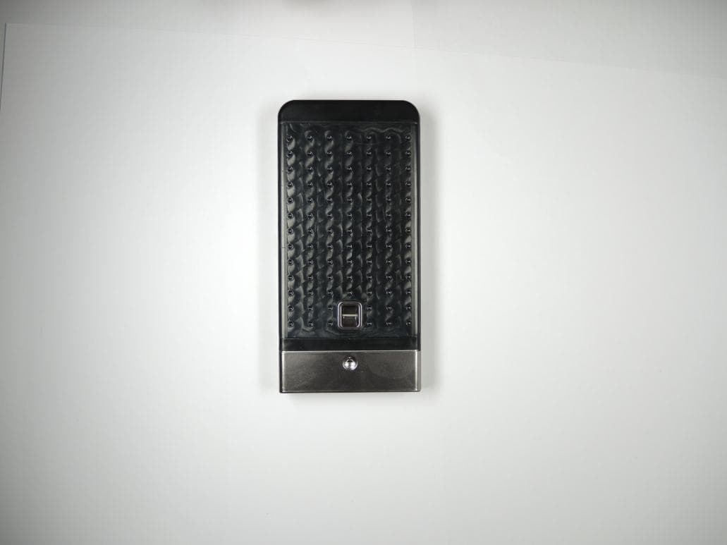
Click to zoom
Application Details
- Equipment Class
- DXX - Part 15 Low Power Communication Device Transmitter
- Date of Grant
- Jun 02, 2015
- Application Purpose
- Original Equipment
- Date of Application
- May 07, 2015
- Equipment Note
- Contactless payment terminal
- Frequency Range
- 13.56000000 - 13.56000000
- Company
- INGENICO
- Country
- France
Documents & Files
Document Text
Text extracted from the exhibit documents filed with the FCC. Open a document above to read the original.
Users Manual
Page 1/2 LCIE Laboratoire de Moirans Z.I. Centr’Alp 170, Rue de Chatagnon 38430 MOIRANS-FRANCE USER MANUAL (FCC STATEMENT) FCCID: XKB-IMP4B2 This is a copy of the page where the FCC statement is included: 900020417 R11 000 01 Page 2/2 LCIE Laboratoire de Moirans Z.I. Centr’Alp 170, Rue de Chatagnon 38430 MOIRANS-FRANCE
Users Manual
Ingenico SA – 28-32 boulevard de Grenelle 75015 Paris - FRANCE Tél. 33(0)1 58 01 80 00 - Fax 33 (0)1 58 01 91 35 ISMP2-Companion- User Guide U S E R G U I D E User Guide • 2/28 Copyright © 2011 Ingenico 900020417 R11 000 01 All rights reserved Contents 1. Introduction __________________________________________________ 4 2. Unpacking ___________________________________________________ 5 3. Recommendations _____________________________________________ 6 3.1. Safety _______________________________________________________________ 6 Sécurité _________________________________________________________________ 6 Sicherheit ________________________________________________________________ 7 3.2. Security of your terminal _______________________________________________ 7 3.3. EC standard compliance marking _________________________________________ 8 3.4. FCC & IC Compliance. __________________________________________________ 8 3.5. Marking ____________________________________________________________ 10 3.6. Bluetooth SIG _______________________________________________________ 12 3.7. Main Characteristics __________________________________________________ 12 4. Installation and connection _____________________________________ 13 4.1. Functional description ________________________________________________ 13 4.2. Battery insertion _____________________________________________________ 15 4.3. Charging ISMP2-Companion ____________________________________________ 16 4.4. Terminal in its environment ____________________________________________ 17 4.5. Power on / off _______________________________________________________ 17 4.6. Connection _________________________________________________________ 18 4.6.1. USB cable connection __________________________________________________________ 18 4.6.2. Cable disconnection ___________________________________________________________ 18 4.7. Payment Integration with Bluetooth _____________________________________ 19 5. Daily use _____________________________________________________ 19 5.1. Getting started with ISMP2-Companion __________________________________ 19 5.2. ISMP2-Companion keypad functions _____________________________________ 19 5.3. Adjusting the contrast ________________________________________________ 20 User Guide • 3/28 Copyright © 2011 Ingenico 900020417 R11 000 01 All rights reserved 5.4. Barcode reader ______________________________________________________ 20 5.5. Card insertion _______________________________________________________ 22 5.5.1. Swiping a card ________________________________________________________________ 22 5.5.2. Inserting a chip card ___________________________________________________________ 22 5.5.3. Reading Contactless (Optional) __________________________________________________ 22 6. Maintenance ________________________________________________ 24 6.1. Cleaning of the terminal _______________________________________________ 24 Entretien du terminal _____________________________________________________ 24 Wartung von Endgeräten __________________________________________________ 24 6.2. Transport and storage ________________________________________________ 25 6.3. Troubleshooting _____________________________________________________ 25 6.4. End of life ___________________________________________________________ 26 Fin de vie _______________________________________________________________ 26 Produktentsorgung _______________________________________________________ 26 User Guide • 4/28 Copyright © 2011 Ingenico 900020417 R11 000 01 All rights reserved 1. Introduction Thank you for choosing a payment terminal Ingenico. We recommend you to read carefully this installation guide: It gives you the necessary information about safety precautions, unpacking, installation, and maintenance of your terminal. WARRANTY / SECURITY To benefit from the guarantee-related product, and to respect the security, we ask you to use only accessories delivered in box with the product, entrusting maintenance operations only to an authorized person. ISMP2-Companion is battery powered, use only Ingenico parts for replacement. ISMP2-Companion can be powered by different sources please respect these recommendations: ISMP2-Companion can be USB powered by using the power supply provided by Ingenico in the packaging. Failure to comply with these instructions will void the manufacturer’s responsibility. This symbol indicates an important Warning. This symbol indicates a piece of advice. User Guide • 5/28 Copyright © 2011 Ingenico 900020417 R11 000 01 All rights reserved 2. Unpacking ADVICE Carefully preserve the packaging of ISMP2-Companion. It must be re-used whenever the terminal is shipped. Products of ISMP2-Companion range are named: IMP4xx According to the model, the following items are included in the ISMP2-Companion box (including optional accessories): The user guide can be an option. WARNING The power supply unit provided with your equipment is specially designed for this Ingenico terminals. Do not use any other power supply. The use of a power supply with apparently similar voltage/current characteristics may damage your terminal. AVERTISSEMENT Dans le cas où vous choisiriez d’utiliser un bloc alimentation, assurez-vous de n’utiliser que le bloc d'alimentation qui a été conçu spécialement pour votre terminal. N'utilisez pas d'autre bloc d'alimentation. L'emploi d'un bloc d'alimentation présentant des caractéristiques apparemment similaires de tension/intensité peut endommager votre terminal. WARNHINWEIS Nur das Netzteil, das speziell für Ihr Gerät ausgelegt wurde, benutzen. Benutzen Sie kein anderes Netzteil. Die Benutzung eines Netzgeräts mit scheinbar ähnlicher Spannung/Stromstärke kann zur Beschädigung Ihres Terminals führen. ADVICE Your terminal is delivered with a protective see through film. We advise that you leave this protective film to ensure optimum protection of your terminal. Film presence does not alter in anyway the use of the termina…
Text truncated - open the document above for the full version.
External Photos
Page 1/4 LCIE Laboratoire de Moirans Z.I. Centr’Alp 170, Rue de Chatagnon 38430 MOIRANS-FRANCE EXTERNAL PHOTOS OF EQUIPMENT FCCID: XKB-IMP4B2 Difference between both references: With or without barcode reader Page 2/4 LCIE Laboratoire de Moirans Z.I. Centr’Alp 170, Rue de Chatagnon 38430 MOIRANS-FRANCE Page 3/4 LCIE Laboratoire de Moirans Z.I. Centr’Alp 170, Rue de Chatagnon 38430 MOIRANS-FRANCE Page 4/4 LCIE Laboratoire de Moirans Z.I. Centr’Alp 170, Rue de Chatagnon 38430 MOIRANS-FRANCE
ID Label/Location Info
Page 1/3 LCIE Laboratoire de Moirans Z.I. Centr’Alp 170, Rue de Chatagnon 38430 MOIRANS-FRANCE PRODUCT LABELING FCCID: XKB-IMP4B2 Page 2/3 LCIE Laboratoire de Moirans Z.I. Centr’Alp 170, Rue de Chatagnon 38430 MOIRANS-FRANCE Page 3/3 LCIE Laboratoire de Moirans Z.I. Centr’Alp 170, Rue de Chatagnon 38430 MOIRANS-FRANCE
Internal Photos
Page 1/4 LCIE Laboratoire de Moirans Z.I. Centr’Alp 170, Rue de Chatagnon 38430 MOIRANS-FRANCE INTERNAL PHOTOS OF EQUIPMENT FCCID: XKB-IMP4B2 Page 2/4 LCIE Laboratoire de Moirans Z.I. Centr’Alp 170, Rue de Chatagnon 38430 MOIRANS-FRANCE Page 3/4 LCIE Laboratoire de Moirans Z.I. Centr’Alp 170, Rue de Chatagnon 38430 MOIRANS-FRANCE Page 4/4 LCIE Laboratoire de Moirans Z.I. Centr’Alp 170, Rue de Chatagnon 38430 MOIRANS-FRANCE
Operational Description
LCIE Laboratoire de Moirans Z.I. Centr’Alp 170, Rue de Chatagnon 38430 MOIRANS-FRANCE GENERAL INFORMATION FCCID: XKB-IMP4B2 1.1. Product description LCIE Laboratoire de Moirans Z.I. Centr’Alp 170, Rue de Chatagnon 38430 MOIRANS-FRANCE LCIE Laboratoire de Moirans Z.I. Centr’Alp 170, Rue de Chatagnon 38430 MOIRANS-FRANCE LCIE Laboratoire de Moirans Z.I. Centr’Alp 170, Rue de Chatagnon 38430 MOIRANS-FRANCE 1.2. Tested System Details See test report 1.3. Test Methodology Both conducted and radiated testing were performed according to the procedures in ANSI C63.4-2003, FCC Part 15 Subpart C. Radiated testing was performed at an antenna to EUT distance of 10 meters. During testing, all equipment’s and cables were moved relative to each other in order to identify the worst case set-up. 1.4. Test facility Tests have been performed on February 12th to 20th, 2015. This test facility has been fully described in a report and accepted by FCC as compliant with the radiated and AC line conducted test site criteria in ANSI C63.4-2003 in a letter dated March 25 th , 2008 (registration number 94821). This test facility has also been accredited by COFRAC (French accreditation authority for European Union test lab accreditation organization) according to NF EN ISO/IEC 17025, accreditation number 1-1633 as compliant with test site criteria and competence in 47 CFR Part 15/ANSI C63.4 and EN55022/CISPR22 norms for 89/336/EEC European EMC Directive application. All pertinent data for this test facility remains unchanged.
RF Exposure Info
RF Exposure Considerations for FCC ID: XKB-IMP4B2 Per FCC KDB 447498 D01 General RF Exposure Guidance v05 The 1-g and 10-g SAR test exclusion thresholds for 100 MHz to 6 GHz at test separation distances ≤ 50 mm are determined by (Eq.1) below: [(max. power of channel, including tune-up tolerance, mW)/(min. test separation distance, mm)] * [√f(GHz)] If result of Eq.1 is less than or equal to the exemption limits below, then corresponding SAR test is not required. SAR Test Configuration Exemption limit 1-g SAR Result of Eq.1 ≤ 3.0 10-g extremity SAR Result of Eq.1 ≤ 7.5 where; f(GHz) is the RF channel transmit frequency in GHz. Power and distance are rounded to the nearest mW and mm before calculation. The result is rounded to one decimal place for comparison. The test exclusions are applicable only when the minimum test separation distance is ≤ 50 mm and for transmission frequencies between 100 MHz and 6 GHz. When the minimum test separation distance is < 5 mm, a distance of 5 mm is applied to determine SAR test exclusion. For our device, the parameters for consideration are as follows: Channel Frequency (GHz) Maximum source-based time averaged conducted output power including tune-up tolerance (mW) Minimum separation distance (mm) Result of Eq. 1 Limit for 1-g SAR Limit for 10-g extremity SAR Verdict 02.402 0.8 5 0.25 37.5 Exempt from SAR 392.441 2.4 5 0.75 37.5 Exempt from SAR 782.480 2 5 0.63 37.5 Exempt from SAR Conclusion: Therefore our device complies with FCC’s RF radiation exposure limits for general population without SAR evaluation.
RF Exposure Info
LCIE Laboratoire de Moirans Z.I. Centr’Alp 170, Rue de Chatagnon 38430 MOIRANS-FRANCE FCCID: XKB-IMP4B2 RF Exposure Information When all the antennas are at least 20cm away from the user’s body (excluding hands and wrists during normal operation of the device), but individual antennas cannot be separated by more than 20cm from each other. If [ Pd(1) / LPd(1) ] + [ Pd(2) / LPd(2) ] + ..... + [ Pd(n) / LPd(n) ] < 1, Then, the device complies with FCC’s RF radiation exposure limit for general population as a portable device (d> 5mm). Where; Pd(n) = Power density of n th transmitter at 5mm LPd(n) = Power density limit for the n th transmitter § 1.1310 Radiofrequency radiation exposure limits. Prediction of MPE limit at a given distance Equation from page 18 of OET Bulletin 65, Edition 97-01 where:S = power density P = power input to the antenna G = power gain of the antenna in the direction of interest relative to an isotropic radiator R = distance to the center of radiation of the antenna 2 4R PG S p = LCIE Laboratoire de Moirans Z.I. Centr’Alp 170, Rue de Chatagnon 38430 MOIRANS-FRANCE Calculations: For 2.4GHz transmitter: S = 0.57mW/cm² at 5mm (Portable) for P=2.0mW and G= -0.5dBi S limit = 1.0mW/cm² Calculation for worst case power output: Maximum peak output power at the antenna terminal:3.00(dBm) Maximum peak output power at the antenna terminal:2.00(mW) Antenna gain(typical):-0.5(dBi) Maximum antenna gain:0.89(numeric) Prediction distance:0.5(cm) Prediction frequency:2480(MHz) MPE limit for uncontrolled exposure at prediction frequency:1(mW/cm^2) Power density at prediction frequency: 0.57(mW/cm^2) For CLESS transmitter: S = 0.00032mW/cm² at 5mm (Portable) for P=0.001mW and G=0dBi S limit = 0.97mW/cm² Maximum peak output power at the antenna terminal:-30.00(dBm) Maximum peak output power at the antenna terminal:0.001(mW) Antenna gain(typical):0(dBi) Maximum antenna gain:1(numeric) Prediction distance:0.5(cm) Prediction frequency:13.56(MHz) MPE limit for uncontrolled exposure at prediction frequency:0.97(mW/cm^2) Power density at prediction frequency: 0.00032(mW/cm^2) Calculation: (Pd(2.4GHz) / LPd(2.4GHz)) + (Pd(FM) / LPd(FM)) = 0.0141 mW/cm² <1 Conclusion: The device complies with FCC’s RF radiation exposure limit for general population as a portable device (d>0.5cm) under the collocation conditions described above.
Test Report
This document shall not be reproduced, except in full, without the written approval of the LCIE. This document contains results related only to the item tested. It does not imply the conformity of the whole production to the item tested .Unless otherwise specified; the decision of conformity takes into account the uncertainty of measures. This document does not anticipate any certification decision. TEST REPORT N°: 827941-R1-E JDE : 133540 Subject Electromagnetic compatibility and Radio spectrum Matters (ERM) tests according to standards: FCC CFR 47 Part 15, Subpart B et C RSS-210 Issue 8 Issued to INGENICO Rovaltain TGV – Quartier de la Gare 26300 – Alixan - FRANCE Apparatus under test Product Terminal ISMP version Companion Trade mark INGENICO Manufacturer INGENICO Model ISMP2 Model under test IMP452-11T2854A Serial number 14344PP00007751 & 14344PP00007752 FCCID XKB-IMP4B2 ICID 2586D-IMP4B2 Test date February 12 th to 20 th , 2015 Test location Moirans IC Test site 6500A-1 & 6500A-3 Test performed by G.Deschamps Composition of document 59 pages Modification of the last version None Document issued on April 20 th , 2015 Written by : Approved by : Gaëtan Deschamps Anthony Merlin Tests operator Technical manager TEST REPORT N°827941-R1-E Page 2/59 SUMMARY 1. SYSTEM TEST CONFIGURATION ..................................................................................................... 3 2. SYSTEM TEST CONFIGURATION ..................................................................................................... 4 3. CONDUCTED EMISSION DATA......................................................................................................... 8 4. RADIATED EMISSION DATA ........................................................................................................... 10 5. MAXIMUM PEAK OUTPUT POWER (15.247) .................................................................................. 16 6. HOPPING CHANNEL SEPARATION (15.247) .................................................................................. 19 7. NUMBER OF HOPPING FREQUENCIES (15.247) ........................................................................... 27 8. TIME OF OCCUPANCY (DWELL TIME) (15.247) ............................................................................. 29 9. BAND EDGE MEASUREMENT (15.247) .......................................................................................... 33 10. OCCUPIED BANDWIDTH ................................................................................................................. 38 12. UNCERTAINTIES CHART ................................................................................................................ 41 13. ANNEX 1 (GRAPHS) ........................................................................................................................ 42 TEST REPORT N°827941-R1-E Page 3/59 1. SYSTEM TEST CONFIGURATION Standard: - FCC Part 15, Subpart C 15.247 - ANSI C63.4 (2003) - RSS-210 Issue 8 – Dec 2010 - RSS-Gen Issue 3 – Dec 2010 EMISSION TEST LIMITS RESULTS (Comments) Limits for conducted disturbance at mains ports 150kHz-30MHz Frequency Quasi-peak value (dBμV) Average value (dBμV) PASS FAIL NA NP 150-500kHz 66 to 56 56 to 46 0.5-5MHz 56 46 5-30MHz 60 50 Radiated emissions 9kHz-30MHz CFR 47 §15.209 (a) CFR 47 §15.247 (d) RSS-210 §A8.5 Measure at 300m 9kHz-490kHz : 67.6dBμV/m /F(kHz) Measure at 30m 490kHz-1.705MHz : 87.6dBμV/m /F(kHz) 1.705MHz-30MHz : 29.5 dBμV/m PASS FAIL NA NP Radiated emissions 30MHz-25GHz* CFR 47 §15.209 (a) CFR 47 §15.247 (d) RSS-210 §A8.5 Highest frequency :400MHz (Declaration of provider) Measure at 3m 30MHz-88MHz : 40 dBμV/m 88MHz-216MHz : 43.5 dBμV/m 216MHz-960MHz : 46.0 dBμV/m 960MHz-1GHz : 54.0 dBμV/m 1GHz – 25GHz: 54.0 dBμV/m (AV) 74.0 dBμV/m (PK) PASS FAIL NA NP Maximum Peak Output Power CFR 47 §15.247 (b) RSS-210 §A8.4(1) Limit: 21dBm Conducted or Radiated measurement PASS FAIL NA NP Hopping Channel Separation CFR 47 §15.247 (a) (1) RSS-210 §A8.1(b) Minimum between: Two-third 20dB Bandwidth or 25kHz Whichever is greater PASS FAIL NA NP Number of Hopping Frequencies CFR 47 §15.247 (a) (1) (iii) RSS-210 §A8.1(d) At least 15 channels used PASS FAIL NA NP Time of Occupancy (Dwell Time) CFR 47 §15.247 (a) (1) (iii) RSS-210 §A8.1(d) Maximum 0.4 sec within 31.6sec PASS FAIL NA NP Band Edge Measurement CFR 47 §15.209 (a) CFR 47 §15.247 (d) RSS-210 §A8.5 Limit: -20dBc PASS FAIL NA NP Occupied bandwidth RSS-Gen §4.6.1 No limit PASS FAIL NA NP Receiver Spurious Emission** RSS-Gen §4.10 See RSS-Gen §4.10 PASS FAIL NA NP *§15.33: The highest internal source of a testing device is defined like more the highest frequency generated or used in the testing device or on which the testing device works or agrees. - If the highest frequency of the internal sources of the testing device is lower than 108 MHz, measurement must be only performed until 1GHz. - If the highest frequency of the internal sources of the testing device ranges between 108 MHz and 500 MHz, measurement must be only performed until 2GHz. - If the highest frequency of the internal sources of the testing device ranges between 500 MHz and 1 GHz, measurement must be only performed until 5GHz. If the highest frequency of the internal sources of the testing device is above 1 GHz, measurement must be only performed until 5 times the highest frequency or 40 GHz, while taking smallest of both. **Testing covered the receive mode, and receiver spurious emissions are considered to be the same as transmitter. TEST REPORT N°827941-R1-E Page 4/59 2. SYSTEM TEST CONFIGURATION 2.1. INFORMATIONS There are 2 models of ISMP2: 2.2. HARDWARE IDENTIFICATION (EUT AND AUXILIARIES): Equipment under test (EUT): IMP452-11T2854A Serial Number: 14344PP00007751 & 14344PP00007752 Photography of EUT Power supply: During all the tests, EUT is supplied by V nom : 3.7 VDC For measurement wit…
Text truncated - open the document above for the full version.
Test Report
This document shall not be reproduced, except in full, without the written approval of the LCIE. This document contains results related only to the item tested. It does not imply the conformity of the whole production to the item tested .Unless otherwise specified; the decision of conformity takes into account the uncertainty of measures. This document does not anticipate any certification decision. TEST REPORT N°: 827941-R2-E JDE : 133540 Subject Electromagnetic compatibility and Radio spectrum Matters (ERM) tests according to standards: FCC CFR 47 Part 15, Subpart B et C RSS-210 Issue 8 Issued to INGENICO Rovaltain TGV – Quartier de la Gare 26300 – Alixan - FRANCE Apparatus under test Product Terminal ISMP version Companion Trade mark INGENICO Manufacturer INGENICO Model ISMP2 Model under test IMP452-11T2854A Serial number 14344PP00007751 & 14344PP00007752 FCCID XKB-IMP4B2 ICID 2586D-IMP4B2 Test date February 12 th to 20 th , 2015 Test location Moirans IC Test site 6500A-1 & 6500A-3 Test performed by G.Deschamps Composition of document 41 pages Modification of the last version None Document issued on April 20 th , 2015 Written by : Approved by : Gaëtan Deschamps Anthony Merlin Tests operator Technical manager TEST REPORT N°827941-R2-E Page 2/41 SUMMARY 1. TEST PROGRAM .................................................................................................................................... 3 2. SYSTEM TEST CONFIGURATION ......................................................................................................... 4 3. CONDUCTED EMISSION DATA ............................................................................................................. 7 4. RADIATED EMISSION DATA (15.209) .................................................................................................... 9 5. FUNDAMENTAL FREQUENCY TOLERANCE (15.225E) ...................................................................... 17 6. BAND-EDGE COMPLIANCE §15.209 ................................................................................................... 19 7. OCCUPIED BANDWIDTH ..................................................................................................................... 21 8. ANNEX 1 (GRAPHS) ............................................................................................................................. 23 9. UNCERTAINTIES CHART ..................................................................................................................... 41 TEST REPORT N°827941-R2-E Page 3/41 1. TEST PROGRAM Standard: - FCC Part 15, Subpart B (Digital Devices) - FCC Part 15, Subpart C - ANSI C63.4 (2003) - RSS-Gen Issue 3 – Dec 2010 - RSS-210 Issue 8 – Dec 2010 EMISSION TEST LIMITS RESULTS (Comments) Limits for conducted disturbance at mains ports 150kHz-30MHz CFR 47 §15.207 Frequency Quasi-peak value (dBμV) Average value (dBμV) PASS FAIL NA NP 150-500kHz 66 to 56 56 to 46 0.5-5MHz 56 46 5-30MHz 60 50 Radiated emissions 9kHz-30MHz CFR 47 §15.209 (a) CFR 47 §15.225 RSS-Gen §4.9 Measure at 300m 9kHz-490kHz : 67.6dBμV/m /F(kHz) Measure at 30m 490kHz-1.705MHz : 87.6dBμV/m /F(kHz) 1.705MHz-30MHz : 29.5 dBμV/m PASS FAIL NA NP Radiated emissions 30MHz-25GHz* CFR 47 §15.209 (a) CFR 47 §15.225 RSS-Gen §4.9 Highest frequency :400MHz (Declaration of provider) Measure at 3m 30MHz-88MHz : 40 dBμV/m 88MHz-216MHz : 43.5 dBμV/m 216MHz-960MHz : 46.0 dBμV/m Above 960MHz : 54.0 dBμV/m PASS FAIL NA NP Fundamental field strength limit CFR 47 §15.225 RSS-210 §A2.6 Operation within the band 13.110-14.010 MHz PASS FAIL NA NP Fundamental frequency tolerance CFR 47 §15.225 RSS-210 §A2.6 Operation within the band 13.110-14.010 MHz PASS FAIL NA NP Band edge compliance CFR 47 §15.225 RSS-210 §A2.6 Operation within the band 13.110-14.010 MHz PASS FAIL NA NP Occupied bandwidth RSS-Gen §4.6.1 No limit PASS FAIL NA NP Receiver Spurious Emission** RSS-Gen §4.10 See RSS-Gen §4.10 PASS FAIL NA NP *§15.33: The highest internal source of a testing device is defined like more the highest frequency generated or used in the testing device or on which the testing device works or agrees. - If the highest frequency of the internal sources of the testing device is lower than 108 MHz, measurement must be only performed until 1GHz. - If the highest frequency of the internal sources of the testing device ranges between 108 MHz and 500 MHz, measurement must be only performed until 2GHz. - If the highest frequency of the internal sources of the testing device ranges between 500 MHz and 1 GHz, measurement must be only performed until 5GHz. If the highest frequency of the internal sources of the testing device is above 1 GHz, measurement must be only performed until 5 times the highest frequency or 40 GHz, while taking smallest of both. **Testing covered the receive mode, and receiver spurious emissions are considered to be the same as transmitter. TEST REPORT N°827941-R2-E Page 4/41 2. SYSTEM TEST CONFIGURATION 2.1. INFORMATIONS There are 2 models of ISMP2: 2.2. HARDWARE IDENTIFICATION (EUT AND AUXILIARIES): Equipment under test (EUT): IMP452-11T2854A Serial Number: 14344PP00007751 & 14344PP00007752 Photography of EUT Power supply: During all the tests, EUT is supplied by V nom : 3.7 VDC For measurement with different voltage, it will be presented in test method. Name Type Rating Reference / Sn Comments Battery AC DC Battery 3.7 VDC 296118442 / None - PHIHONG AC DC Battery 100-240 VAC to 5 VDC, 0.3 A to 1 A and 50/60Hz PSAI05R-050Q / D142700110A1 PHIHONG TEST REPORT N°827941-R2-E Page 5/41 Inputs/outputs - Cable: Access Type Length used (m) Declared <3m Shielded Under test Comments PHIHONG AC/DC 1.2 - Access1 Mini USB - Auxiliary equipment used during test: Type Reference Sn Comments Contactless card - - SAM - - Two used. Contact card - - IPod A1509 CCQKTK66FFCJ - Radio frequency - Equipment information (2 R…
Text truncated - open the document above for the full version.
Test Setup Photos
Page 1/3 LCIE Laboratoire de Moirans Z.I. Centr’Alp 170, Rue de Chatagnon 38430 MOIRANS-FRANCE CONDUCTED AND RADIATED MEASUREMENT PHOTO FCCID: XKB-IMP4B2 1.1 Conducted emission Page 2/3 LCIE Laboratoire de Moirans Z.I. Centr’Alp 170, Rue de Chatagnon 38430 MOIRANS-FRANCE 1.2 Radiated emissions Page 3/3 LCIE Laboratoire de Moirans Z.I. Centr’Alp 170, Rue de Chatagnon 38430 MOIRANS-FRANCE
Contact Information
Applicant
Nicolas Jacquemont(Certification Manager)
Test Firm
LCIE Etablissement Sud-EstAnthony Merlin
Technical Specifications
| # | Rule Parts | Frequency Range | Power Output |
|---|---|---|---|
| 1 | 15C | 13.56 MHz - 13.56 MHz | - |
Other Applications from INGENICO
XKB-DX8AM
Aug 06, 2026Smart POS Terminal
Equipment Class
PCB - PCS Licensed TransmitterXKB-INGA02WF
Apr 03, 2026Smart Module
Equipment Class
DSS - Part 15 Spread Spectrum TransmitterXKB-INGA02WU
Mar 25, 2026Smart Module
Equipment Class
DTS - Digital Transmission SystemXKB-MOBEM3TOC
Dec 24, 2025Mobile Payment Terminal
Equipment Class
DXX - Part 15 Low Power Communication Device Transmitter
XKB-RX9CLWBT
Aug 26, 2024Payment terminal
Equipment Class
NII - Unlicensed National Information Infrastructure TX