XKB-IUC16XCLContactless payment terminal
INGENICO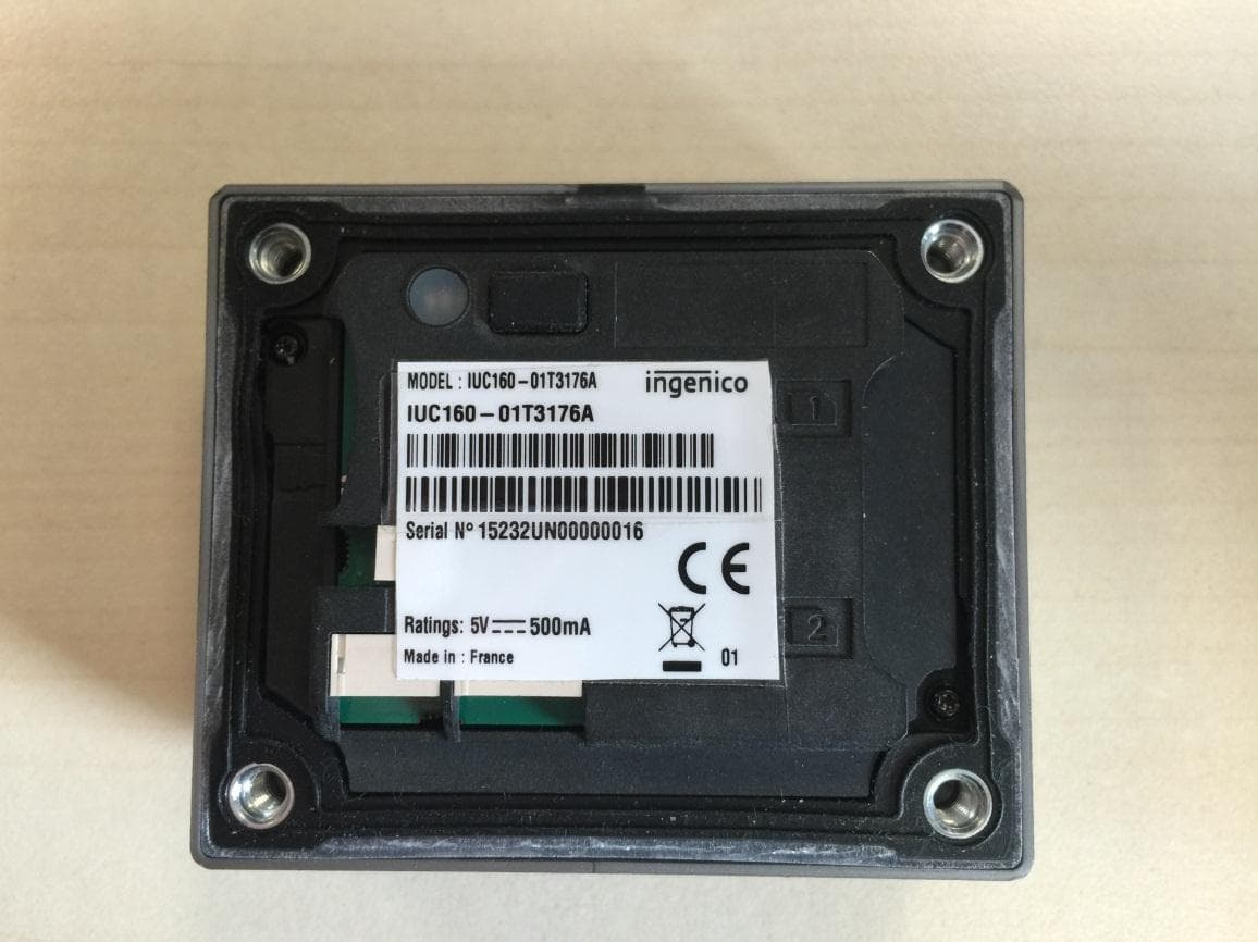
Click to zoom
Application Details
- Equipment Class
- DXX - Part 15 Low Power Communication Device Transmitter
- Date of Grant
- Dec 13, 2015
- Application Purpose
- Original Equipment
- Date of Application
- Dec 13, 2015
- Equipment Note
- Contactless payment terminal
- Frequency Range
- 13.56000000 - 13.56000000
- Company
- INGENICO
- Country
- France
Documents & Files
Document Text
Text extracted from the exhibit documents filed with the FCC. Open a document above to read the original.
Users Manual
www.ingenico.com 28-32, boulevard de Grenelle, 75015 Paris - France / (T) +33 (0)1 58 01 80 00 / (F) +33 (0)1 58 01 91 35 Ingenico - SA au capital de 47 656 332 / 317 218 758 RCS Nanterre iUC160B Quick start and installation guide iUC160B 900022579 R11 000 01/0915 Copyright© 2015 Ingenico All rights reserved 2 Contents 1_Introduction 2_Recomendation 2_1 Safety 2_2 Security of your terminal 2_3 Integration (see installation guide*) 2_4 EC standard compliance marking 2_5 IC statements 2_6 FCC Statement 3_Maintenance 3_1 Transport and storage 3_2 Environment (WEEE, Batteries and Packaging) 3 5 5 6 7 7 Save this information Leaflet and file in a safe place ! 7 8 iUC160B 900022579 R11 000 01/0915 Copyright© 2015 Ingenico All rights reserved 3 1_Introduction Thank you for choosing a payment terminal Ingenico. We recommend you to read carefully this installation guide: It gives you the necessary information about safety precautions, unpacking, installation, and maintenance of your terminal. Danke, dass Sie sich für einen Zahlungsterminal Ingenico entschieden haben. Wir empfehlen Ihnen, diese Installationsanleitung sorgfältig durchzulesen. Sie enthält die erforderlichen Informationen zu den Sicherheitsvorkehrungen, dem Auspackung, der Installation und der Wartung Ihres Terminals. Merci d’avoir choisi un terminal de paiement Ingenico. Nous vous recommandons de lire attentivement ce guide d’installation: Il vous donne les informations nécessaires sur les précautions de sécurité, le déballage, l’installation et l’entretien de votre terminal. WARRANTY / SECURITY To benefit from the guarantee-related product, and to respect the security, we ask you to use only accessories delivered in box with the product, entrusting maintenance operations only to an authorized person. GARANTIE / SICHERHEIT Anspruch nehmen zu können und die Sicherheit zu gewährleisten, bitten wir Sie, nur die in der mit dem Erzeugnis gelieferten Karton enthaltenen Zubehörteile zu verwenden und die Wartung einer dazu befugten Person anzuvertrauen. GARANTIE / SECURITE Pour bénéficier de la garantie liée au produit, et afin de respecter la sécurité, nous vous demandons de n’utiliser que des accessoires livrés dans la boîte avec le produit, en confiant les opérations de maintenance seulement à une personne autorisée. iUC160B 900022579 R11 000 01/0915 Copyright© 2015 Ingenico All rights reserved 4 The power sources should comply with Standards IEC 60950-1: 2005 (2nd Edition) +/A1:2009 +/A2:2013 and EN 60950-1: 2006 +/A11:2009 +/A1:2010 +/A12:2011 +/A2:2013. Moreover, they should be Safety Extra-Low Voltage circuits and Power Limited Sources according to clauses 2.2 and 2.5 of these standards. Die Stromquellen sollten den Normen IEC 60950-1: 2005 (Ausgabe 2) +/A1:2009 +/A2:2013 und EN 60950-1: 2006 +/A11:2009 +/ A1:2010 +/A12:2011 +/A2:2013 entsprechen. Zudem sollte es sich dabei um Schutzkleinspannungen und begrenzte Stromquellen gemäß den Bestimmungen 2.2 und 2.5 dieser Normen handeln. iUC160B power ratings: 5 V max 500mA Nota: Failure to comply with these instructions will void the manufacturer’s responsibility. Hinweis: Bei Nichteinhaltung dieser Anweisungen wird die Haftung des Herstellers aufgehoben. Nota: le non respect de ces instructions annule la responsabilité du fabricant. This symbol indicates an important Warning. Dieses Symbol stellt ein wichtiges Warnzeichen dar. Ce symbole indique un avertissement important. Nennleistungen des iUC160B: 5 V max 500mA Les alimentations électriques doivent être conformes aux normes IEC 60950-1: 2005 (2nd Edition) +/A1:2009 +/A2:2013 et EN 60950-1: 2006 +/A11:2009 +/ A1:2010 +/A12:2011 +/A2:2013. De plus, elles doivent être des circuits Très Basse Tension de Sécurité et être des Sources à Puissance Limitée conformément aux chapitres 2.2 et 2.5 de ces normes. Caractéristiques électriques d’alimentation des iUC160B: 5 V max 500mA : courant continu iUC160B 900022579 R11 000 01/0915 Copyright© 2015 Ingenico All rights reserved 5 2_Recomendation 2_1 Safety Power on/Power down To power on or power down the iUC160B connect or disconnect the USB cable. Starten /stoppen Für starten oder stoppen iUC160B anschließen oder abziehen Kabel USB. Mise en marche / Arrêt Pour allumer ou éteindre l’iUC160B connectez ou débranchez le câble USB. Lithium battery The iUC160B is fitted with a lithium battery which is not accessible to the user. Only a qualified technician may be authorized to open the unit and change this component. For switzerland annex 2.15 of SR 814.81 applies for batteries. Lithium Batterie Die iUC160B sind mit einer Lithium-Batterie ausgestattet, die nicht für den Benutzer zugänglich. Nur ein qualifizierter Techniker können ermächtigt werden, das Gerät zu öffnen und ändern Sie die Komponente werden Für die Schweiz 2,15 2,15 Anhang von SR 814.81 gilt für Batterien Pile au lithium Les iUC160B sont munis d’une pile au lithium qui n’est pas accessible à l’utilisateur. Seul un technicien qualifié peut être autorisé à ouvrir l’appareil et à changer ce composant. Pour la Suisse l’annexe 2.15 de la SR 814.81 s’applique pour les batteries. iUC160B 900022579 R11 000 01/0915 Copyright© 2015 Ingenico All rights reserved 6 Connections to external equipment and circuits All external circuits and equipment connected to iUC160B should be Safety Extra-Low Voltage circuits and be Limited power sources within the meaning of sections 2.2 and 2.5 of Standards IEC 60950-1: 2005 +/ A1:2009 +/A2:2013 and EN 60950-1: 2006 +/A11:2009 +/A1:2010 +/ A12:2011 +/A2:2013. Verbindungen zu externen Geräten und Schaltungen Alle externen Schaltungen und Geräten, die an iUC160B sollte Safety Extra-Low Voltage-Schaltungen und sein Begrenzte Energiequellen im Sinne der Abschnitte 2.2 und 2.5 von Standards IEC 60950-1: 2005 +/ A1:2009 +/A2:2013 und EN 60950-1: 2006 +/A11:2009 +/A1:2010 +/ A12:2011 +/A2:2013. Connexion aux équipements et circuits externes Tous les circuits et équipements externes connectés aux iUC160B doivent être des c…
Text truncated - open the document above for the full version.
External Photos
Page 1/3 LCIE Laboratoire de Moirans Z.I. Centr’Alp 170, Rue de Chatagnon 38430 MOIRANS-FRANCE EXTERNAL PHOTOS OF EQUIPMENT FCCID: XKB-IUC16XCL Page 2/3 LCIE Laboratoire de Moirans Z.I. Centr’Alp 170, Rue de Chatagnon 38430 MOIRANS-FRANCE Page 3/3 LCIE Laboratoire de Moirans Z.I. Centr’Alp 170, Rue de Chatagnon 38430 MOIRANS-FRANCE
ID Label/Location Info
Page 1/1 LCIE Laboratoire de Moirans Z.I. Centr’Alp 170, Rue de Chatagnon 38430 MOIRANS-FRANCE PRODUCT LABELING FCCID: XKB-IUC16XCL Position on EUT:
Internal Photos
Page 1/6 LCIE Laboratoire de Moirans Z.I. Centr’Alp 170, Rue de Chatagnon 38430 MOIRANS-FRANCE INTERNAL PHOTOS OF EQUIPMENT FCCID: XKB-IUC16XCL Page 2/6 LCIE Laboratoire de Moirans Z.I. Centr’Alp 170, Rue de Chatagnon 38430 MOIRANS-FRANCE Page 3/6 LCIE Laboratoire de Moirans Z.I. Centr’Alp 170, Rue de Chatagnon 38430 MOIRANS-FRANCE Page 4/6 LCIE Laboratoire de Moirans Z.I. Centr’Alp 170, Rue de Chatagnon 38430 MOIRANS-FRANCE Page 5/6 LCIE Laboratoire de Moirans Z.I. Centr’Alp 170, Rue de Chatagnon 38430 MOIRANS-FRANCE Page 6/6 LCIE Laboratoire de Moirans Z.I. Centr’Alp 170, Rue de Chatagnon 38430 MOIRANS-FRANCE
Operational Description
LCIE Laboratoire de Moirans Z.I. Centr’Alp 170, Rue de Chatagnon 38430 MOIRANS-FRANCE GENERAL INFORMATION FCCID: XKB-IUC16XCL 1.1. Product description LCIE Laboratoire de Moirans Z.I. Centr’Alp 170, Rue de Chatagnon 38430 MOIRANS-FRANCE 1.2. Tested System Details Equipment under test (EUT): Photography of EUT Power supply: During all the tests, EUT is supplied by V nom : 5VDC For measurement with different voltage, it will be presented in test method. Name Type Rating Reference / Sn Comments Supply1 AC DC Battery USB From Laptop 5V – 500mA - - Inputs/outputs - Cable Access Type Length used (m) Declared <3m Shielded Under test Access1 USB power supply 2 Access2 COM0 RS232 2 Access3 SAM2 / Access4 SAM1 / Access5 μSD Card – MMC / Access6 Wake Up (2 Wires) 0.3 Auxiliary equipment used during test Type Reference Sn Comments Laptop LENOVO 8896-2FG L3-B7463 LCIE Laboratoire de Moirans Z.I. Centr’Alp 170, Rue de Chatagnon 38430 MOIRANS-FRANCE Equipment information: RF module: NC Frequency band: [13.553–13.567 ] MHz Sub-band REC7003: Annexe g(f) RF mode: Transmitter Transceiver Receiver Standby Product class § 7.1.4 1 2 3 Receiver classification § 4.1.1 1 2 3 Antenna type: External: Internal: Antenna gain: NC Extreme temperature range: Category I (General) -20°C to +55°C Performed at-30°C to +70°C Category II (Portable) -10°C to +55°C Category III (Indoor) +5°C to +35°C Extreme test source voltage: ±10%: other: 5V – 5.5Vdc NC : Not communicated by customer 1.3. Test Methodology Both conducted and radiated testing were performed according to the procedures in ANSI C63.4, FCC Part 15 Subpart C. Radiated testing was performed at an antenna to EUT distance of 10 meters. During testing, all equipment’s and cables were moved relative to each other in order to identify the worst case set-up. 1.4. Test facility Tests have been performed on from September 18th to 28th, 2015. This test facility has been fully described in a report and accepted by FCC as compliant with the radiated and AC line conducted test site criteria in ANSI C63.4 (registration number 94821). This test facility has also been accredited by COFRAC (French accreditation authority for European Union test lab accreditation organization) according to NF EN ISO/IEC 17025, accreditation number 1-1633 as compliant with test site criteria and competence in 47 CFR Part 15/ANSI C63.4 and EN55022/CISPR22 norms for 89/336/EEC European EMC Directive application. All pertinent data for this test facility remains unchanged.
Test Report
This document shall not be reproduced, except in full, without the written approval of the LCIE. This document contains results related only to the item tested. It does not imply the conformity of the whole production to the item tested .Unless otherwise specified; the decision of conformity takes into account the uncertainty of measures. This document does not anticipate any certification decision. TEST REPORT N°: 838096-R1-E JDE : 137851 Subject Electromagnetic compatibility and Radio spectrum Matters (ERM) tests according to standards: FCC CFR 47 Part 15, Subpart B et C RSS-210 Issue 8.1 Issued to INGENICO Rovaltain TGV – Quartier de la Gare 9 Avenue de la gare 26958 VALENCE CEDEX 9 Apparatus under test Product Lecteur RFID / RFID Reader Trade mark INGENICO Manufacturer INGENICO Model under test IUC160-01T3176A Serial number 15232UN00000016 FCCID XKB-IUC16XCL ICID 2586D-IUC16XCL Test date Du 18 au 28 Septembre 2015 / From September 18 th to 28 th , 2015 Test location Moirans IC Test site 6500A-1 & 6500A-3 Test performed by Jonathan PAUC / Jonathan SARTO Composition of document 31 pages Modification of the last version None Document issued on November 2 nd , 2015 Written by : Approved by : Jonathan PAUC Anthony MERLIN Tests operator Technical manager TEST REPORT N°838096-R1-E Page 2/31 SUMMARY 1. TEST PROGRAM .................................................................................................................................... 3 2. SYSTEM TEST CONFIGURATION ......................................................................................................... 4 3. CONDUCTED EMISSION DATA ............................................................................................................. 6 4. RADIATED EMISSION DATA (15.209) .................................................................................................... 8 5. FUNDAMENTAL FREQUENCY TOLERANCE (15.225E) ...................................................................... 15 6. BAND-EDGE COMPLIANCE §15.209 ................................................................................................... 17 7. OCCUPIED BANDWIDTH ..................................................................................................................... 19 8. ANNEX 1 (GRAPHS) ............................................................................................................................. 21 9. UNCERTAINTIES CHART ..................................................................................................................... 31 TEST REPORT N°838096-R1-E Page 3/31 1. TEST PROGRAM Standard: - FCC Part 15, Subpart B (Digital Devices) - FCC Part 15, Subpart C - ANSI C63.10 (2013) - RSS-210 Issue 8.1 – Feb 2015 - RSS-Gen Issue 4 – Nov 2014 EMISSION TEST LIMITS RESULTS (Comments) Limits for conducted disturbance at mains ports 150kHz-30MHz CFR 47 §15.207 Frequency Quasi-peak value (dBμV) Average value (dBμV) PASS FAIL NA NP 150-500kHz 66 to 56 56 to 46 0.5-5MHz 56 46 5-30MHz 60 50 Radiated emissions 9kHz-30MHz CFR 47 §15.209 (a) CFR 47 §15.225 RSS-Gen §4.9 Measure at 300m 9kHz-490kHz : 67.6dBμV/m /F(kHz) Measure at 30m 490kHz-1.705MHz : 87.6dBμV/m /F(kHz) 1.705MHz-30MHz : 29.5 dBμV/m PASS FAIL NA NP Radiated emissions 30MHz-2GHz* CFR 47 §15.209 (a) CFR 47 §15.225 RSS-Gen §4.9 Highest frequency : 390MHz (Declaration of provider) Measure at 3m 30MHz-88MHz : 40 dBμV/m 88MHz-216MHz : 43.5 dBμV/m 216MHz-960MHz : 46.0 dBμV/m Above 960MHz : 54.0 dBμV/m PASS FAIL NA NP Fundamental field strength limit CFR 47 §15.225 RSS-210 §A2.6 Operation within the band 13.110-14.010 MHz PASS FAIL NA NP Fundamental frequency tolerance CFR 47 §15.225 RSS-210 §A2.6 Operation within the band 13.110-14.010 MHz PASS FAIL NA NP Band edge compliance CFR 47 §15.225 RSS-210 §A2.6 Operation within the band 13.110-14.010 MHz PASS FAIL NA NP Occupied bandwidth RSS-Gen §4.6.1 No limit PASS FAIL NA NP Receiver Spurious Emission** RSS-Gen §4.10 See RSS-Gen §4.10 PASS FAIL NA NP *§15.33: The highest internal source of a testing device is defined like more the highest frequency generated or used in the testing device or on which the testing device works or agrees. - If the highest frequency of the internal sources of the testing device is lower than 108 MHz, measurement must be only performed until 1GHz. - If the highest frequency of the internal sources of the testing device ranges between 108 MHz and 500 MHz, measurement must be only performed until 2GHz. - If the highest frequency of the internal sources of the testing device ranges between 500 MHz and 1 GHz, measurement must be only performed until 5GHz. If the highest frequency of the internal sources of the testing device is above 1 GHz, measurement must be only performed until 5 times the highest frequency or 40 GHz, while taking smallest of both. **Testing covered the receive mode, and receiver spurious emissions are considered to be the same as transmitter. TEST REPORT N°838096-R1-E Page 4/31 2. SYSTEM TEST CONFIGURATION 2.1. HARDWARE IDENTIFICATION (EUT AND AUXILIARIES): Equipment under test (EUT): IUC160-01T3176A Serial Number: 15232UN00000016 Photography of EUT Power supply: During all the tests, EUT is supplied by V nom : 5VDC For measurement with different voltage, it will be presented in test method. Name Type Rating Reference / Sn Comments Supply1 AC DC Battery USB From Laptop 5V – 500mA - - Inputs/outputs - Cable Access Type Length used (m) Declared <3m Shielded Under test Access1 USB power supply 2 Access2 COM0 RS232 2 Access3 SAM2 / Access4 SAM1 / Access5 μSD Card – MMC / Access6 Wake Up (2 Wires) 0.3 Auxiliary equipment used during test Type Reference Sn Comments Laptop LENOVO 8896-2FG L3-B7463 TEST REPORT N°838096-R1-E Page 5/31 Equipment information: RF module: NC Frequency band: [13.553–13.567 ] MHz Sub-band REC7003: Annexe g(f) RF mode: Trans…
Text truncated - open the document above for the full version.
Test Setup Photos
Page 1/4 LCIE Laboratoire de Moirans Z.I. Centr’Alp 170, Rue de Chatagnon 38430 MOIRANS-FRANCE CONDUCTED AND RADIATED MEASUREMENT PHOTO FCCID: XKB-IUC16XCL 1.1 Conducted emission Page 2/4 LCIE Laboratoire de Moirans Z.I. Centr’Alp 170, Rue de Chatagnon 38430 MOIRANS-FRANCE 1.2 Radiated emissions Test setup in anechoic chamber (Pos Z) Page 3/4 LCIE Laboratoire de Moirans Z.I. Centr’Alp 170, Rue de Chatagnon 38430 MOIRANS-FRANCE Test setup in anechoic chamber (Pos XY) – setup >1GHz Page 4/4 LCIE Laboratoire de Moirans Z.I. Centr’Alp 170, Rue de Chatagnon 38430 MOIRANS-FRANCE Test setup in anechoic chamber (Pos Z) – setup >1GHz
Contact Information
Applicant
Nicolas Jacquemont(Certification Manager)
Test Firm
LCIE Etablissement Sud-EstAnthony Merlin
Technical Specifications
| # | Rule Parts | Frequency Range | Power Output |
|---|---|---|---|
| 1 | 15C | 13.56 MHz - 13.56 MHz | - |
Other Applications from INGENICO
XKB-DX8AM
Aug 06, 2026Smart POS Terminal
Equipment Class
PCB - PCS Licensed TransmitterXKB-INGA02WF
Apr 03, 2026Smart Module
Equipment Class
DSS - Part 15 Spread Spectrum TransmitterXKB-INGA02WU
Mar 25, 2026Smart Module
Equipment Class
DTS - Digital Transmission SystemXKB-MOBEM3TOC
Dec 24, 2025Mobile Payment Terminal
Equipment Class
DXX - Part 15 Low Power Communication Device Transmitter
XKB-RX9CLWBT
Aug 26, 2024Payment terminal
Equipment Class
NII - Unlicensed National Information Infrastructure TX