XKB-M5CLWBTV2Mobile payment terminal
INGENICO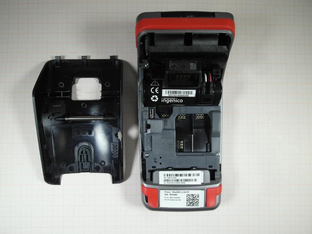
Click to zoom
Application Details
- Equipment Class
- DXX - Part 15 Low Power Communication Device Transmitter
- Date of Grant
- Jan 05, 2023
- Application Purpose
- Original Equipment
- Date of Application
- Jan 05, 2023
- Equipment Note
- Mobile payment terminal
- Frequency Range
- 13.56000000 - 13.56000000
- Company
- INGENICO
- Country
- France
Documents & Files
Document Text
Text extracted from the exhibit documents filed with the FCC. Open a document above to read the original.
Users Manual
www.ingenico.com 28-32, boulevard de Grenelle, 75015 Paris - France / (T) +33 (0)1 58 01 80 00 / (F) +33 (0)1 58 01 91 35 Ingenico - SA au capital de 47 656 332 / 317 218 758 RCS Nanterre Move 5000 User Guide Optional Move 5000 900017771 R11 000 12/0419 Copyright© 2019 Ingenico All rights reserved 2 Contents 1_Introduction 2_Presentation 2_1 Content of the box 2_2 Overview on the MOVE/5000 2_3 Keyboard details and functionality 2_4 Touch panel 3_Use of the terminal 3_1 Switching off the terminal 3_2 Reading card 3_3 Scan Engine (Optional) 4_Installation 4_1 Recommendations 4_2 Terminal connections 4_2_1 uUSB 4_2_2 DC Jack 4_2_3 MicroSD memory Card 4_2_4 Audio Jack (optional) 4_3 Opening trap door 4_4 SAMs & SIMs 4 5 13 5 8 6 14 9 10 10 10 13 14 14 16 17 15 15 12 Move 5000 900017771 R11 000 12/0419 Copyright© 2019 Ingenico All rights reserved 3 4_5 Battery 4_5_1 Main characteristics 4_5_2 Installing the battery 4_5_3 Charging the battery 4_5_4 Changing the battery 4_6 Paper roll 4_6_1 Main characteristics of INGENICO paper roll 4_6_2 Installing paper roll 5_Recommendations 5_1 Safety 5_2 Security of your terminal 5_3 Fixed installation 6_Standards 6_1 Environment (WEEE, Batteries and Packaging) 6_2 FCC/IC Compliance 6_3 MIC Compliance 7_Troubleshooting 18 18 18 20 21 22 22 23 24 24 25 28 26 28 29 34 33 Move 5000 900017771 R11 000 12/0419 Copyright© 2019 Ingenico All rights reserved 4 1_Introduction We hope that you will be fully satisfied with your new terminal MOVE/5000. This terminal is available in different models. Please select by yourself in this documentation items related to your model. Read this guide to understand and make the best use of your terminal. It presents you the necessary information about use, installation, maintenance, safety and security recommendations. WARRANTY / SECURITY Use only the power supply included with the product to ensure best performance and safety. Maintenance should only be provided by Ingenico authorized technician. Failure to comply with these instructions will void the manufacturer’s responsibility. This symbol indicates an important Warning. This symbol indicates a piece of advice. Move 5000 900017771 R11 000 12/0419 Copyright© 2019 Ingenico All rights reserved 5 2_Presentation WARNING The power supply unit provided with your equipment is specially designed for Ingenico terminals. Do not use any other power supply. The use of a power supply with apparently similar voltage/current characteristics may damage your terminal. 2_1Content of the box MOVE/5000 terminal unit equipped with a paper roll A battery pack disconnected User guide Power adapter Move 5000 900017771 R11 000 12/0419 Copyright© 2019 Ingenico All rights reserved 6 ADVICE Keep the packaging. It must be re-used whenever the termi- nal is shipped. 2_2Overview of the MOVE/5000 Terminal unit 3’’5 LCD Display with touch panel Backlit keyboard Smart card reader Easy loading printer Magnetic card reader Move 5000 900017771 R11 000 12/0419 Copyright© 2019 Ingenico All rights reserved 7 Compartment where are located: the battery pack the modules SAM1/SAM2/SIM1/SIM2 the 2nd Smart card reader (optional) Move 5000 900017771 R11 000 12/0419 Copyright© 2019 Ingenico All rights reserved 8 2_3 Keyboard details and functiona- lity Weight (without paper roll nor battery) 310g Dimensions (L x w x h)169x78x57 mm Electrical mains network 100-240VAC / 50-60 Hz - Class II equipment Connections on terminal Micro USB AB serial link Power connector Contacts for Cradle Some keys can have other functions according to the appli- cations that are in the terminal. The functions key accesses the different application menus The red key cancels the procedure in progress The yellow key cancels the last character The green key validates input selections and information. It is also used to switch on the terminal Feed paper a few centimers if pressed for a long time (more than 2 seconds) Move 5000 900017771 R11 000 12/0419 Copyright© 2019 Ingenico All rights reserved 9 2_4 Touch panel Move/5000 features touch screen display, allowing user interaction via finger or a stylus. Note that there are 2 different stylus pens depending on the touch screen type, one for Move/5000 with resistive touch screen and one for Move/5000 with capacitive touch screen as shown below : Capacitive stylus Resistive stylus Stylus location Retractable stylus is located at the back cover as shown above : Move 5000 900017771 R11 000 12/0419 Copyright© 2019 Ingenico All rights reserved 10 3_Use of the terminal 3_1 Switching off the terminal ADVICE Before to use the terminal, always check if the roll of paper is present. If the battery is empty and the terminal in use is removed from its base, the terminal automatically shuts off. It may also be switch by pressing simultaneously and (yellow key) for one second. In order to restart the terminal, press on the keyboard. 3_2 Reading card Magnetic stripe card The card can be read either from bottom to top or from top to bottom, with the stripe facing the terminal. Use a regular movement in order to ensure a reliable card reading. Move 5000 900017771 R11 000 12/0419 Copyright© 2019 Ingenico All rights reserved 11 Card reader: insert the card horizontally with the chip facing upwards and leave in position throughout the transaction. Smart card 2nd card reader (Optional): is located under terminal trapdoor (on back of the terminal). Insert the card up side down chip facing the terminal. Bring the card firmly up to the active zone. Keep the card close to the reader during the transaction Contactless (optional) The 4 virtual LEDs are displayed during the transaction. The terminal behavior for the cardholder may depend on: The terminal environment Local usage (language...) Move 5000 900017771 R11 000 12/0419 Copyright© 2019 Ingenico All rights reserved 12 3_3 Scan Engine (Optional) An optional Camera Autofocus with LED or an optional Barcode module can be fitted on back of Move/5000 terminal (dedicated reference…
Text truncated - open the document above for the full version.
Users Manual
Move 5000 900017771 R11 000 12/0419 Copyright© 2019 Ingenico All rights reserved 27 CAUTION Positioning of the terminal on check stand must be in such a way to make cardholder PIN (Personal Identification Number) spying infeasible. Installing device on an adjustable stand must be in such a way that consumers can swivel the terminal sideways and/ or tilt it forwards/backwards to a position that makes visual observation of the PIN-entry process difficult. Positioning of in-store security cameras such that the PIN- entry keypad is not visible. NEVER ask the customer to divulge their PIN Code. Customers should be advised to ensure that they are not being overloo- ked when entering their PIN Code. 5_3 Fixed installation If the device is to be used in a situation where it is not possible for the cardholder to pick up and shield their PIN entry themselves, the device may be used without PIN shield, but it must be installed in the following manner: a) The device must be angled at 45 or more, so that oversight of the PIN entry from the rear of the device is not possible. b) The device must either be fitted in a swivel stand – so that the customer can position the device in the best angle to prevent oversight – or the device must be fixed in the best possible position to prevent oversight if such a generic position exists in the specific environment to which the device is installed. c) The device environment must be accompanied with conspicuous notices and educational material which informs the customer to shield their PIN during PIN entry. d) The device must be deployed so that oversight from other customers, either in different payment lanes, or in other areas of the shopping environment, is prevented. This may be achieved through the placement of the lanes and device, so that the customer is automatically positioned between the device keypad and other customers. Alternatively, it may be achieved by the environment in which the device is installed, so that the checkout itself shields the PIN entry process. e) The terminal is exclusively made for indoor use. If the above conditions are not fulfilled, the device with PIN shield must be used. Move 5000 900017771 R11 000 12/0419 Copyright© 2019 Ingenico All rights reserved 28 6_Standards 6_1 Environment (WEEE, Batteries and Packaging) This product is labeled in accordance with European Directives 2002/96/EC concerning Waste Electrical and Electronic Equipment (WEEE) and 2006/66/EC concerning Batteries and Accumulators. Those provisions are requiring producers and manufacturers to become liable for take-back, treatment and recycling upon end of life of equipment and batteries. The associated symbol means that WEEE and waste batteries must not be thrown away but collected separately and recycled. Ingenico ensures that efficient collection and recycling schemes are set-up for WEEE and batteries according to the local regulation of your country. Please contact your retailers for more detailed information about the compliance solution in place for disposing of your old product and used batteries. Packaging waste must also be collected separately to assure a proper disposal and recycling. Please note that proper recycling of the electrical and electronic equipment and waste batteries will ensure safety of human health and environment. Move 5000 900017771 R11 000 12/0419 Copyright© 2019 Ingenico All rights reserved 29 6_2 FCC/IC Compliance This equipment has been tested and found to comply with the limits for a Class B digital device, pursuant to part 15 of the FCC Rules. These limits are designed to provide reasonable protection against harmful interference in a residential installation. This equipment generates, uses and can radiate radio frequency energy and, if not installed and used in accordance with the instruction, may cause harmful interference to radio communications. However, there is no guarantee that interference will not occur in a particular installation. If this equipment does cause harmful interference to radio or television reception which can be determined by turning the equipment off and on, the user is encouraged to try to correct interference by one or more of the following measures : Reorient or relocate the receiving antenna. Increase the separation between the equipment and receiver. Connect the equipment into an outlet on circuit different from that to which the receiver is connected. Consult the dealer or an experienced radio/TV technician for help. This device complies with Part 15 of the FCC Rules and Industry Canada license-exempt RSS standard(s). Operation is subject to the following two conditions: (1) This device may not cause harmful interference, and (2) This device must accept any interference received, including interference that may cause undesired operation. Le présent appareil est conforme aux CNR d’Industrie Canada applicables aux appareils radio exempts de licence. L’exploitation est autorisée aux deux conditions suivantes : (1) l’appareil ne doit pas produire de brouillage, et (2) l’utilisateur de l’appareil doit accepter tout brouillage radioélectrique subi, même si le brouillage est susceptible d’en compromettre le fonctionnement. You are cautioned that changes or modifications not expressly approved by the part responsible for compliance could void the user’s authority to operate the equipment. Move 5000 900017771 R11 000 12/0419 Copyright© 2019 Ingenico All rights reserved 30 Under Industry Canada regulations, this radio transmitter may only operate using an antenna of a type and maximum (or lesser) gain approved for the transmitter by Industry Canada. To reduce potential radio interference to other users, the antenna type and its gain should be so chosen that the equivalent isotropically radiated power (e.i.r.p.) is not more than that necessary for successful communication. Conformément à la réglementation d’Industrie Canada, le présent émetteur radio peut fonctionner avec une antenne d’un type et d’un gain m…
Text truncated - open the document above for the full version.
Cover Letter(s)
CONFIDENTIALITY REQUEST for Certification Service in USA Federal Communication Commission Equipment Authorization Division, Application Processing Branch 7435 Oakland Mills Road Columbia, MD 21048 2022-12-09 TO WHOM IT MAY CONCERN Pursuant to Paragraphs §0.457 and 0.459 of the Commission’s Rules (47 C.F.R.) and Section §552(b)(4) of the Freedom of Information Act, we requests confidentiality for the following products: FCC ID XKB-M5CLWBTV2 Model name Move/5000 For the product stated above, we request permanent confidentiality for exhibits which contain Operational Description, B lock Diagram, Schematics, Parts Lists or Tune Up Information. The above exhibits contain our trade secrets and proprietary information that could be of benefit to our competitors. If you have any questions, please feel free to contact me at the address shown below. Sincerely, Name: Nicolas Jacquemont Comp any: INGENICO Address: 9 Avenue de la Gare, Rovaltain TGV, BP 25156, 26958 Valence, France Cedex 9
External Photos
External photos of the EU T – Move/5000 Photo 1: Photo 2: Photo 3:
ID Label/Location Info
ingenico FCC ID: J(K8-M5000CLW1 IC : 2588D -M5000CLW1 Product: Movt/5000 CL/WiFi/BT V2 Move/5000 CL/WiFi/BT V2
Internal Photos
Internal photos of the EUT – M5CLWBTV2 Photo 1: Photo 2 Phot o 3:
Internal Photos
Photo 3: Photo 5: Photo 4: Photo 6: Photo 7: Photo 8:
Test Report
TEST REPORT Test report no.: 1-4835_22-02-15 Testing laboratory Applicant CTC advanced GmbH Untertuerkheimer Strasse 6 – 10 66117 Saarbruecken / Germany Phone: + 49 681 5 98 - 0 Fax: + 49 681 5 98 - 9075 Internet: https://www.ctcadvanced.com e-mail: [email protected] Accredited Testing Laboratory: The testing laboratory (area of testing) is accredited according to DIN EN ISO/IEC 17025 (2018-03) by the Deutsche Akkreditierungsstelle GmbH (DAkkS) The accreditation is valid for the scope of testing procedures as stated in the accreditation certificate starting with the registration number: D-PL-12076-01. Ingenico Group 9 Avenue de la Gare Rovaltain 26958 Valence Cedex 9 / FRANCE Phone: -/- Contact: Georges Allemand e-mail: [email protected] Manufacturer Ingenico Group 9 Avenue de la Gare Rovaltain 26958 Valence Cedex 9 / FRANCE Test standard/s FCC - Title 47 CFR Part 15 FCC - Title 47 of the Code of Federal Regulations; Chapter I; Part 15 - Radio frequency devices RSS - 210 Issue 10 Spectrum Management and Telecommunications Radio Standards Specification - Licence-Exempt Radio Apparatus: Category I Equipment For further applied test standards please refer to section 3 of this test report. Test Item Kind of test item: Payment Terminal Model name: Move/5000 FCC ID: XKB-M5CLWBTV2 ISED certification number: 2586D-M5CLWBTV2 Frequency: 13.56MHz Technology tested: RFID Antenna: Integrated antenna Power supply: 3.4 V to 4.2 V DC by battery, AC/DC adapter PHIHONG AM08R-50B Temperature range: -20°C to +45°C This test report is electronically signed and valid without handwritten signature. For verification of the electronic signatures, the public keys can be requested at the testing laboratory. Test report authorized: Test performed: Christoph Schneider Hans-Joachim Wolsdorfer Lab Manager Lab Manager Radio Communications Radio Communications Test report no.: 1-4835_22-02-15 © CTC advanced GmbH Page 2 of 29 1 Table of contents 1 Table of contents ............................................................................................................................................. 2 2 General information ......................................................................................................................................... 3 2.1 Notes and disclaimer ........................................................................................................................... 3 2.2 Application details ............................................................................................................................... 3 2.3 Test laboratories sub-contracted ........................................................................................................ 3 3 Test standard/s, references and accreditations .............................................................................................. 4 4 Reporting statements of conformity – decision rule ...................................................................................... 5 5 Test environment ............................................................................................................................................. 6 6 Test item........................................................................................................................................................... 6 6.1 General description ............................................................................................................................. 6 6.2 Additional information......................................................................................................................... 6 7 Description of the test setup ............................................................................................................................ 7 7.1 Shielded semi anechoic chamber ....................................................................................................... 8 7.2 Shielded fully anechoic chamber ...................................................................................................... 10 7.3 AC conducted................................................................................................................................... 11 7.4 Conducted measurements normal and extreme conditions ............................................................. 12 8 Measurement uncertainty .............................................................................................................................. 13 9 Summary of measurement results ................................................................................................................ 14 10 Additional comments ................................................................................................................................ 15 11 Measurement results ................................................................................................................................ 16 11.1 Occupied bandwidth .......................................................................................................................... 16 11.2 Field strength of the fundamental ..................................................................................................... 18 11.3 Field strength of the harmonics and spurious .................................................................................. 19 11.4 Conducted limits ............................................................................................................................... 23 11.5 Frequency error ................................................................................................................................. 26 12 Glossary ..................................................................................................................................................... 27 13 Document history ..........................................................................................…
Text truncated - open the document above for the full version.
Test Setup Photos
Annex D No.1-4835/22-02-01_Annex_D Setup photos of the Device Under Test This document is electronically signed and valid without handwritten signature. For verification of the electronic signatures, the public keys can be requested at the testing laboratory. Document authorized: Hans-Joachim Wolsdorfer Lab Manager Radio Communications CTC advanced GmbHUntertuerkheimer Str. 6-10 66117 Saarbruecken / Germany Phone: +49 681 5 98 - 0 Fax: +49 681 5 98 - 9075 web: ctcadvanced.com e-mail: [email protected] Photos Annex D Photo 1 Photo 2 2022-10-13Document 1-4835/22-02-01_Annex_D2/4 Photo 3 Photo 4 2022-10-13Document 1-4835/22-02-01_Annex_D3/4 Photo 5 - END OF DOCUMENT - 2022-10-13Document 1-4835/22-02-01_Annex_D4/4
Contact Information
Applicant
Nicolas Jacquemont(Certification Manager)
Test Firm
cetecom advanced GmbHGerald Schmidt
Technical Specifications
| # | Rule Parts | Frequency Range | Power Output |
|---|---|---|---|
| 1 | 15C | 13.56 MHz - 13.56 MHz | - |
Other Applications from INGENICO
XKB-DX8AM
Aug 06, 2026Smart POS Terminal
Equipment Class
PCB - PCS Licensed TransmitterXKB-INGA02WF
Apr 03, 2026Smart Module
Equipment Class
DSS - Part 15 Spread Spectrum TransmitterXKB-INGA02WU
Mar 25, 2026Smart Module
Equipment Class
DTS - Digital Transmission SystemXKB-MOBEM3TOC
Dec 24, 2025Mobile Payment Terminal
Equipment Class
DXX - Part 15 Low Power Communication Device Transmitter
XKB-RX9CLWBT
Aug 26, 2024Payment terminal
Equipment Class
NII - Unlicensed National Information Infrastructure TX