XKB-ML30Payment Terminal
INGENICO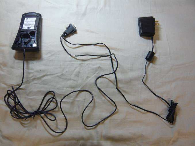
Click to zoom
Application Details
- Equipment Class
- JBP - Part 15 Class B Computing Device Peripheral
- Date of Grant
- Jan 31, 2010
- Application Purpose
- Original Equipment
- Date of Application
- Jan 31, 2010
- Equipment Note
- Payment Terminal
- Company
- INGENICO
- Country
- France
Documents & Files
Document Text
Text extracted from the exhibit documents filed with the FCC. Open a document above to read the original.
Attestation Statements
Date : 01-20-2009 Declaration We, the undersigned INGENICO hereby declares that the model number ML30-322A-0101 and ML30-312A- 0101. Referenced with the grantee code XKB-ML30 doesn’t contain any intentional radiator circuit. FCC ID : XKB-ML30 Trade Name Model Number ML30 ML30-322A-0101 ML30 ML30-312A-0101 INGENICO 1, rue Claude Chappe BP 346 07503 Guilherand Granges – France Marc DELORME Marc DELORME Quality Manager [email protected] Signature
Cover Letter(s)
January 19 th , 2010 CONFIDENTIALITY REQUEST Curtis-Straus LLC - TCB 1 Distribution Center Circle #1 Littleton, MA 01460 USA Re: Confidentiality request for a Digital Device FCC ID: XKB-ML30 Gentlemen, INGENICO SA requests, pursuant to 47CFR 0.459, post grant confidentiality for portions of the material contained in this application. The following document regarding this submission for FCC ID: XKB-ML30 shall be kept confidential: 1. Block Diagram description of the ML30 (file: Block Diagram-XKB-ML30.pdf) Specifically, these exhibits contain information relating to circuit function and complexity that could be of benefit to competitors. The material contains trade secrets and confidential information that INGENICO does not customarily release to the public and which is otherwise not generally available to the public. Regards, Marc DELORME Quality Manager 1, rue Claude Chappe – BP 346 07503 GUILHERAND GRANGES - France
External Photos
FCC ID: XKB-ML30 Page 1/4 EXTERNAL PHOTOS OF TESTED EUT FCC ID: XKB-ML30 Page 2/4 Lower face connection port FCC ID: XKB-ML30 Page 3/4 RS232 Configuration (ML30-312A-0101) FCC ID: XKB-ML30 Page 4/4 RS232 configuration (power supply unit) USB Configuration
ID Label/Location Info
FCC ID: XKB-ML30 Page 1/2 PRODUCT LABELING Label#1 (RS232 configuration) Label#1 (USB configuration) FCC ID: XKB-ML30 Page 2/2 Label#2 (USB & RS232 configuration) Label#1 Label#2
Internal Photos
FCC ID: XKB-ML30 Page 1/4 INTERNAL PHOTOS OF TESTED EUT General view, cover removed, rear face General view, rear cover Component view, lower face FCC ID: XKB-ML30 Page 2/4 Component view, rear face CIU TREILLIS board (Front & Rear side) Component view, rear face without CIU TREILLIS board FCC ID: XKB-ML30 Page 3/4 Component view, upper face Component view, Behind LCD FCC ID: XKB-ML30 Page 4/4
Operational Description
FCC ID: XKB-ML30 Page 1/3 OPERATIONAL DESCRIPTION 1.1. ML30 description FCC ID: XKB-ML30 Page 2/3 FCC ID: XKB-ML30 Page 3/3 1.2. Related Submittal(s) / Grant(s) All host equipment used in the test configuration are FCC granted, when relevant. 1.3. Justification Test was performed on ML30-322A-0101 Serial number: 09310PP10000102 with “USB cable option” and “RS232 option cable + power supply adapter FRIWO Ref: 153051). Reference 322A and 312A indicates only whether apparatus is sold with USB or RS232 configurations. 1.4. Tested System Details The FCC IDs for all equipment, plus description of all cables used in the tested system are: Trade Mark – Model Number (Serial number) FCC ID Description Cable description ML30-322A-0101 (USB option cable) XKB-ML30 Bank payment terminal USB cable unshielded (2m) ML30-312A-0101 (RS232 option cable) XKB-ML30 Bank payment terminal RS232 cable unshielded (3m) DC power supply cable (2m) Power adapter: 153051 FRIWO 120Vac / 60Hz RS232 configuration Laptop DELL VOSTRO 1710 sn: T932DA00 None Laptop Power cable unshielded Power supply DELL unit (CN-ODF266-71615-76L-C8FC) None Adaptor AC/DC Power cable unshielded Smartcard (Bank card) Sn: none - - - SAM cards (x2) Sn: none - - - * : Equipment under test 1.5. Test Methodology Both conducted and radiated testing were performed according to the procedures in ANSI C63.4-2003, FCC Part 15 Subpart B. Radiated testing was performed at an antenna to EUT distance of 10 meters. During testing, all equipment’s and cables were moved relative to each other in order to identify the worst case set-up. 1.6. Test facility Tests have been performed on November 12 th , 2009. This test facility has been fully described in a report and accepted by FCC as compliant with the radiated and AC line conducted test site criteria in ANSI C63.4-2003 in a letter dated March 25 th , 2008 (registration number 94821). This test facility has also been accredited by COFRAC (French accreditation authority for European Union test lab accreditation organization) according to NF EN ISO/IEC 17025, accreditation number 1-1633 as compliant with test site criteria and competence in 47 CFR Part 15/ANSI C63.4 and EN55022/CISPR22 norms for 89/336/EEC European EMC Directive application. All pertinent data for this test facility remains unchanged.
Test Report
RAPPORT D'ESSAI / TEST REPORT N° 200909-5696C-A1-R1-E Page : 2 / 21 SUMMARY 1. TEST PROGRAM ................................................................................................................................... 3 2. APPARATUS UNDER TEST: CONFIGURATION ................................................................................... 4 3. MEASUREMENT OF CONDUCTED EMISSION (150KHZ-30MHZ) ....................................................... 5 4. MEASUREMENT OF RADIATED EMISSION (30MHZ-1GHZ)................................................................ 7 5. TEST EQUIPMENT LIST ...................................................................................................................... 11 6. UNCERTAINTIES CHART .................................................................................................................... 13 7. ANNEX 1 (GRAPHS) ............................................................................................................................ 14 RAPPORT D'ESSAI / TEST REPORT N° 200909-5696C-A1-R1-E Page : 3 / 21 1. TEST PROGRAM Standard : FCC CFR 47, PART 15, Subpart B ANSI C63-4 (2003). Requirements for unintentional radiator. Class B computer peripheral. - Radiated emissions from 30MHz to 2GHz - Conducted emissions from 150kHz to 30MHz * Highest internal frequency: 171MHz General conclusion: Measures performed on the sample of the product ML30, SN: 09310PP10000102, in configuration and description presented in this test report, show compliance levels with FCC CFR 47, Part 15 B . RAPPORT D'ESSAI / TEST REPORT N° 200909-5696C-A1-R1-E Page : 4 / 21 2. APPARATUS UNDER TEST: CONFIGURATION 2.1. JUSTIFICATION Test was performed on ML30-322A-0101 Serial number: 09310PP10000102 with “USB cable option” and “RS232 option cable + power supply adapter FRIWO Ref: 153051). Reference 322A and 312A indicates only whether apparatus is sold with USB or RS232 configurations. 2.2. HARDWARE IDENTIFICATION (EUT AND AUXILIARIES): ML30-322A-0101 (USB option cable) Serial number: 09310PP10000102 ML30-312A-0101 (RS232 option cable + Power supply adapter FRIWO) RS232 and USB mode, With mains power adapter: 153051 FRIWO 120Vac / 60Hz – 400mA (DC cable attached on adapter: 2m; used for RS232 mode) - Soft: TEST CEM V01.02 - Internal max frequencies: 171MHz - Colour screen driver 25.1.1 • Input/output: - DC power input (8Vdc) - USB (Slave) or RS232 port • Cables: - 1x DC power supply cable (fixed on mains power unit), unshielded: 2m - 1x RS232 Com cable: 3m P/N: 252678837 - 1x USB cable: 2m P/N: 252292872 • Auxiliaries equipment used during test: - 1 x Laptop DELL VOSTRO 1710 Sn: T932DA00 - 1 x Smartcard (Opuce EMV card) - 2 x SAM cards • Auxiliaries equipment used during test: Trade Mark – Model Number (Serial number) FCC ID Description Cable description Laptop DELL VOSTRO 1710 sn: T932DA00 None Laptop Power cable unshielded Power supply DELL unit (CN-ODF266-71615-76L-C8FC) None Adaptor AC/DC Power cable unshielded 2.3. UNNING MODE The inboard software (EMC TEST) performed the followings tests and activates the followings functions: - Smartcards reading: CAM0, SAM1 / SAM2 (Power ON and reading) - Backlight and display are ON 2.4. EQUIPMENT MODIFICATIONS None 2.5. SPECIAL ACCESSORIES 1 x Ferrite core on mains power adapter FRIWO 153051 (DC side). Power supply: USB mode: USB port of the PC (5V) (configuration n°1) RS232 mode: power adapter 8Vdc (configuration n°2) RAPPORT D'ESSAI / TEST REPORT N° 200909-5696C-A1-R1-E Page : 5 / 21 3. MEASUREMENT OF CONDUCTED EMISSION (150KHZ-30MHZ) 3.1. TEST CONDITIONS Date of test : November 12th, 2009 Test performed by : J PAUC Humidity : 38% Temperature : 21°C Pressure : 992mB 3.2. SETUP FOR CONDUCTED EMISSIONS MEASUREMENT The product has been tested according to ANSI C63.4-(2003) and FCC Part 15 subpart B. The product has been tested with 110V/60Hz power line voltage on laptop power supply and compared to the FCC Part 15 subpart B §15.107 limits. Measurement bandwidth was 9 kHz from 150 kHz to 30 MHz. The EUT with its auxiliaries are set on a non-conducting 80cm above the ground reference plane. The distance between the EUT and the LISN is 80cm. The EUT is 40cm away for the vertical ground plane. The EUT is powered through the laptop that is powered through the LISN (measure). Measurement is made with a Rohde & Schwarz ESU8 receiver in peak mode. This was followed by a Quasi-Peak, i.e. CISPR measurement for any strong signal. If the average limit is met when using a Quasi-Peak detector, the EUT shall be deemed to meet both limits and measurement with the average detector is unnecessary. The LISN (measure and auxiliaries) is 50Ω / 50μH. The Peak data are shown on plots in annex 1. Quasi-Peak and Average measurements are detailed in a table with frequencies and levels measured. Interconnecting cables and equipment's were moved to position that maximized emission. A summary of the worst case emissions found in all test configurations and modes is shown on the following page. RAPPORT D'ESSAI / TEST REPORT N° 200909-5696C-A1-R1-E Page : 6 / 21 Configuration n°1 (USB Mode, 322A-0101) Configuration n°2 (RS232 Mode, 312A-0101) 3.3. DIVERGENCE, ADDITION OR SUPPRESSION ON THE TEST SPECIFICATION None 3.4. MEASUREMENTS RESULTS Mains terminals 110Vac/60Hz: Measurements are performed on the phase (L1) and neutral (N) of the power line of the PC. Measure on L: graph Emc#1 (Configuration n°1, USB mode) (see annex 1) Measure on N: graph Emc#2 (Configuration n°1, USB mode) (see annex 1) Measure on L: graph Emc#3 (Configuration n°2, RS232 mode) (see annex 1) Measure on N: graph Emc#4 (Configuration n°2, RS232 mode ) (see annex 1) RESULT: PASS RAPPORT D'ESSAI / TEST REPORT N° 200909-5696C-A1-R1-E Page : 7 / 21 4. MEASUREMENT OF RADIATED EMISSION (30MHZ-2GHZ) 4.1. TEST CONDITIONS Date of test : November 12th, 2009 Test performed by : J PAUC Humidity : 38% Temperature : 21°C Pressure : 992mB 4.2. SETUP FOR RADIATED EMISSIONS MEASUREMENT The installati…
Text truncated - open the document above for the full version.
Test Setup Photos
FCC ID: XKB-ML30 Page 1/2 1 CONDUCTED AND RADIATED MEASUREMENT PHOTO 1.1 Conducted emission Configuration n°1 (USB Mode, 322A-0101) Configuration n°2 (RS232 Mode, 312A-0101) FCC ID: XKB-ML30 Page 2/2 1.2 Radiated emission Configuration n°1 (USB Mode, 322A-0101) Configuration n°2 (RS232 Mode, 312A-0101)
Contact Information
Applicant
Nicolas Jacquemont(Certification Manager)
Test Firm
LCIE Sud-EstJacques Lorquin
Technical Specifications
| # | Rule Parts | Frequency Range | Power Output |
|---|---|---|---|
| 1 | 15B | - | - |
Other Applications from INGENICO
XKB-DX8AM
Aug 06, 2026Smart POS Terminal
Equipment Class
PCB - PCS Licensed TransmitterXKB-INGA02WF
Apr 03, 2026Smart Module
Equipment Class
DSS - Part 15 Spread Spectrum TransmitterXKB-INGA02WU
Mar 25, 2026Smart Module
Equipment Class
DTS - Digital Transmission SystemXKB-MOBEM3TOC
Dec 24, 2025Mobile Payment Terminal
Equipment Class
DXX - Part 15 Low Power Communication Device Transmitter
XKB-RX9CLWBT
Aug 26, 2024Payment terminal
Equipment Class
NII - Unlicensed National Information Infrastructure TX