XLXA3900Wireless Thermostat
Beijing HaiLin Auto Controls Equipment Co., Ltd.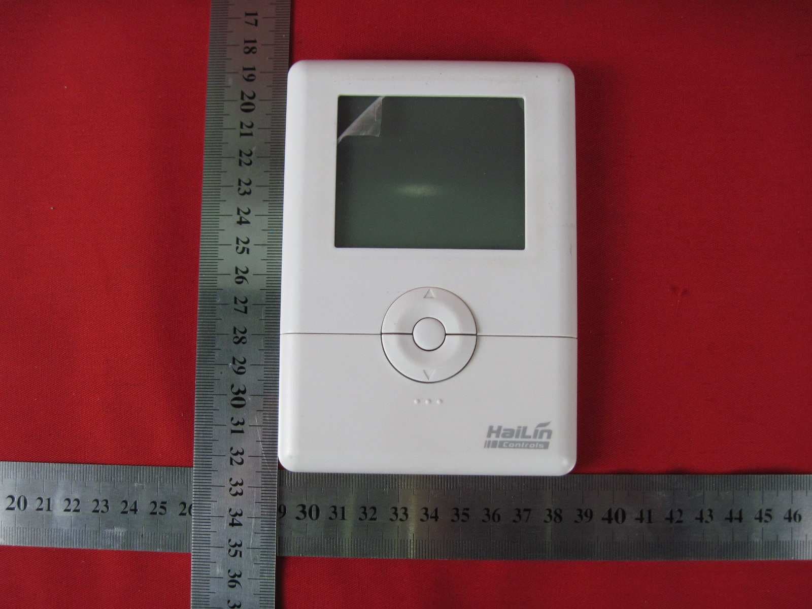
Click to zoom
Application Details
- Equipment Class
- DSR - Part 15 Remote Control/Security Device Transceiver
- Date of Grant
- Jan 11, 2011
- Application Purpose
- Original Equipment
- Date of Application
- Jan 10, 2011
- Equipment Note
- Wireless Thermostat
- Frequency Range
- 433.59400000 - 434.59400000
- Country
- China
Documents & Files
Document Text
Text extracted from the exhibit documents filed with the FCC. Open a document above to read the original.
Users Manual
Wireless Thermostat Owners Manual Model:A3900 The product is a thermostat which consists of two parts, one is sender which normally used in client room to send client’s adjustment code, and the other is controller which normally used with central air conditioner to receive the adjustment code of sender part and to adjust air conditioner. Please note that the thermostats need to wake up by pressing the middle button for 5seconds when they are first use. Press the middle round button which is between the “UP” and “DOWN” keys for 5seconds till the display shows ”PE”, the thermostat will disable wireless functions and goes into “Stand By” mode to save the battery energy. Press it again for another 5 seconds to restart the thermostat. This wireless thermostat working at frequency 433.34MHz. Sender: FEATURES Structure of thermostat and explanation for the keypads We are pleased you have selected one of our broad line of wall thermostats. Our products are manufactured to high quality standards and are designed for years of service. REMOVE THE MYLAR LABEL FROM THE LCD DISPLAY WINDOW. ARMCHAIR PROGRAMMING 1. You can program your thermostat prior to installation by following these instructions and starting at the configuration menu. This can be done while you relax in your favorite chair and is a very good way to familiarize yourself with all the functions of your thermostat. The following time and temperature settings are pre-programmed into the thermostat: COMPRESSOR PROTECTION 2. The thermostat provides a 4 minutes delay after shutting of the heating or cooling system before it can be restarted. This feature will prevent damage to your compressor caused by rapid cycling. Note that this delay also applies to the heating system control. It does not provide a delay when there are power outages. You can select the function on or off at the configuration. TEMPERATURE RANGE 3. This thermostat can be programmed between 45 ̊F and 95 ̊F (7 ̊C and 35 ̊C). However, it will display room temperatures from 30 ̊F to 99 ̊F (0 ̊C and 37 ̊C). This thermostat will automatically cutoff in Heat mode if the temperature rises above 95 ̊F (35 ̊C), and automatically cutoff in Cool mode if the temperature drops below 45 ̊F (7 ̊C). POWER SUPPLY 4. The thermostat is supplied with a Li-battery. You can charge the Lithium battery through a USB cable (included) connected to a PC. During the charge process the battery icon will flash on and off. Note: The Lithium battery should be charged over 12 hours for the first 3 times to properly condition the battery. Low Battery Warning 5. Your thermostat has a battery warning system. When the batteries are first detected to be weak, the first stage low battery warning is indicated by battery symbol flashing on the LCD display. At your earliest convenience, you need to charge the batteries through USB. During the charging process the battery icon will flash one by one. When the battery charge completes, the battery icon will disappear. WIRELESS Modulation: GFSK WIRELESS Tx/Rx Datarate: 10KBaud WIRELESS Tx/Rx Deviation: 19KHZ WIRELESS CHANNEL Wireless Channel Communications Center Frequency Allowable Frequency Differences 1 433.594 MHZ ±30KHZ 2 433.794 MHZ ±30KHZ 3 433.994MHZ ±30KHZ 4 434.194 MHZ ±30KHZ 5 434.394 MHZ ±30KHZ 6 434.594 MHZ ±30KHZ INSTALLATION What You Need This thermostat includes two #8 slotted screws and two wall anchors for mounting. To install your thermostat, you should have the following tools and materials. ■ Slotted Screwdriver(s) ■ Small Philips screwdriver ■ Hammer ■ Electric drill and 3/16” bit OPERATION Standby mode When remove the thermostat from the box, the temperature will update after a few second. You can choose to set the thermostat or enter “Standby” mode. Press and hold the middle round button which is between the “UP” and “DOWN” keys for 5 seconds, “PE” will be displayed on the LCD to indicate Standby Mode. When you are ready to use the thermostat, press and hold the round button for 5 seconds to exit Standby Mode. NOTE: We suggest you to change the thermostat to “Stand By” mode when you don’t use the thermostat for a long time. Fan Operation If your system does not have a G terminal connection, skip to the next section (Heating system).. 1. Turn on the power switch of the system. 2. Press FAN key to ON mode. The blower should begin to operate. 3. Press FAN key to AUTO mode. The blower should stop immediately Heating System (SPAN=2,SP2=2) 1. Press the MODE key until HEAT shows on the LCD display. 2. Press to adjust thermostat setting to 2°F(1°C)above room temperature. The heating system should begin to operate. The display should show “Heat On”. However, if the “Wait” is displaying and flashing, the compressor lockout feature is operating (see Configuration menu, item 10). 3. Adjust temperature setting to 4°F(2°C)above room temperature. If your system configuration is set to “HP1” or “HP2”, the auxiliary heat system should begin to operate and the display should show “AUX Heat On”. 4. When the room temperature above the thermostat setting, the heating system should stop operating. Emergency System EMER MODE bypasses the Heat Pump to use the heat source wired to terminal E/W1 on the Controller. EMER Mode is typically used when the compressor has failed or the outdoor temperature is too cold to run the heat pump. 1. Press the MODE key to select EMER mode, “EMER” will show on the display. 2. Press to adjust thermostat temperature setting above room temperature. The Emergency. Heating system will begin to operate. The display will show “Heat On” “EMER” to indicate that the system is operating. 3. When the room temperature above the thermostat setting. The Emergency heating system should stop operating. Cooling System (SPAN=2,SP2=2) 1. Press MODE key to select the Cool mode. 2. Press to adjust thermostat setting below room temperature. The blower should come on immediately, followed by cold air circulation. The display should show “Cool On”. 3. Adjust te…
Text truncated - open the document above for the full version.
Cover Letter(s)
Confidential Letter of Beijing HaiLin Auto Controls Equipment Co., Ltd.
Cover Letter(s)
Beijing Hailin Auto Controls Equipment Co., Ltd. Shahe Industrial Zone, Changping Distric (8610)52816666-1311 Request for Supercede TO: Federal Communication Commission Please kindly be notified that we, Beijing Hailin Auto Controls Equipment Co., Ltd. herein request to supercede the FCC ID: XLXA3900 for the following reason: 1. There is one mistake for the test equipment list in the test report due to the reversing of the equipment model and S/N information. We are willing to correct it and replace the report. Please kindly permit the supercede. Thank you. Sincerely, (Signature) Name / Title: Yongming Huang/ Engineer Company: Beijing Hailin Auto Controls Equipment Co., Ltd. Tel: (8610)52816666-1311 Fax: Email: [email protected]
External Photos
External Photos
ID Label/Location Info
Wireless Thermostat Model:A3900 Power supply: DC 4.2V Beijing Hailin Auto Controls Equipment Co., Ltd. Shahe Industrial Zone, Changping District, Beijing, 102206, P.R.China FCCID:XLXA3900 This device complies with part 15 of the FCC Rules. Operation is subject to the following two conditions: (1) this device may not cause harmful interference received, and (2) this device must accept any interference received, including interference that may cause undesired operation.
Internal Photos
Internal Photos Internal Photos Internal Photos
Test Report
Produkte Products Prüfbericht - Nr.: Test Report No.: 18000211 001 Seite 1 von 23 Page 1 of 23 Auftraggeber: Client: Beijing Hailin Electric Equipment Co., Ltd Shahe Industrial Zone, Changping District, Beijing 102206 P.R.China Gegenstand der Prüfung: Test item: Wireless Thermostat Bezeichnung: Identification: A3900 Serien-Nr.: Serial No.: Engineering Sample Wareneingangs-Nr.: Receipt No.: 1143001493 Eingangsdatum: Date of receipt: 2009-07-03 Prüfort: Testing location: Refer to section 1.1 Prüfgrundlage: Test specification: FCC Part 15 Subpart C: 2009 Prüfergebnis: Test Result: Der Prüfgegenstand entspricht oben genannter Prüfgrundlage(n). The test items passed the test specification(s). Prüflaboratorium: Testing Laboratory: Refer to section 1.1 geprüft/ tested by: 2010-12-22 Yang, Kai/PE kontrolliert/ reviewed by: 2010-12-22 Sun, Lixun/TC Datum Date Name/Stellung Name/Position Unterschrift Signature Datum Date Name/Stellung Name/Position Unterschrift Signature Sonstiges/ Other Aspects: Abkürzungen: P(ass) = entspricht Prüfgrundlage F(ail) = entspricht nicht Prüfgrundlage N/A = nicht anwendbar N/T = nicht getestet Abbreviations: P(ass) = passed F(ail) = failed N/A = not applicable N/T = not tested Produkte Products Prüfbericht - Nr.: Test Report No.: 18000211 001 Seite 2 von 23 Page 2 of 23 TEST SUMMARY 4.1.1 SECTION 15.203 ANTENNA REQUIREMENT Result: Passed 4.1.2 SECTION 15.231 (C) 20DB BANDWIDTH TESTING Result: Passed 4.1.3 SECTION 15.205, SECTION 15.209, SECTION 15.231 (B) RADIATED EMISSION Result: Passed 4.1.4 SECTION 15.231 (A) LIMITING OPERATIONS AND DURATION OF TRANSMISSION Produkte Products Prüfbericht - Nr.: Test Report No.: 18000211 001 Seite 3 von 23 Page 3 of 23 Contents 1 TEST SITES ..............................................................................................................................................................4 1.1 TEST FACILITIES..................................................................................................................................................4 1.2 LIST OF TEST AND MEASUREMENT INSTRUMENTS...............................................................................................4 2 GENERAL PRODUCT INFORMATION..............................................................................................................5 2.1 PRODUCT FUNCTION AND INTENDED USE............................................................................................................5 2.2 RATINGS AND SYSTEM DETAILS..........................................................................................................................5 2.3 INDEPENDENT OPERATION MODES......................................................................................................................5 2.4 NOISE GENERATING AND NOISE SUPPRESSING PARTS.........................................................................................5 2.5 SUBMITTED DOCUMENTS.....................................................................................................................................5 3 TEST SET-UP AND OPERATION MODES .........................................................................................................6 3.1 TEST SPECIFICATION............................................................................................................................................6 3.2 PRINCIPLE OF CONFIGURATION SELECTION.........................................................................................................6 3.3 PHYSICAL CONFIGURATION FOR TESTING............................................................................................................6 3.4 TEST OPERATION AND TEST SOFTWARE..............................................................................................................6 3.5 SPECIAL ACCESSORIES AND AUXILIARY EQUIPMENT..........................................................................................6 3.6 COUNTERMEASURES TO ACHIEVE EMC COMPLIANCE.........................................................................................6 4 SUMMARY OF TEST RESULTS...........................................................................................................................7 4.1 TEST RESULT.......................................................................................................................................................8 4.1.1 Section 15.203 Antenna Requirement..........................................................................................................8 4.1.2 Section 15.231 (c) 20dB Bandwidth Testing ...............................................................................................9 4.1.3 Section 15.205, Section 15.209, Section 15.231 (b) Radiated Emission ...................................................11 4.1.4 Section 15.231 (a) Limiting operations and duration of transmission ......................................................21 5 PHOTOGRAPHS OF THE TEST SET-UP .........................................................................................................22 6 LIST OF TABLES ..................................................................................................................................................23 7 LIST OF FIGURES ................................................................................................................................................23 8 LIST OF PHOTOGRAPHS ...................................................................................................................................23 Produkte Products Prüfbericht - Nr.: Test Report No.: 18000211 001 Seite 4 von 23 Page 4 of 23 1 Test Sites 1.1 Test Facilities Laboratory: Audix Technology (Shenzhen) Co., Ltd. (2.948 listed) Address: No.6 Ke Feng Road, Block 52, Shenzhen Science & Industry park Nantou, Shenzhen, Guangdong, China The used test equipment is in accordance with CISPR 16-1 for measurement of radio interference. …
Text truncated - open the document above for the full version.
Test Setup Photos
Photograph 1: Set-up for measurement of radiated emission, <1GHz Photograph 2: Set-up for measurement of radiated emission, >1GHz
Contact Information
Applicant
Yongming Huang(Testing Engineer)
Technical Contact
TUV Rheinland (China) Ltd.Yang Kai
010-65666660
Unit 707, AVIC Bldg., No.10B, Central Road, · Beijing · China
Test Firm
Audix Technology (Shenzhen) Co.Smart Tsai
Technical Specifications
| # | Rule Parts | Frequency Range | Power Output |
|---|---|---|---|
| 1 | 15.231 | 433.594 MHz - 434.594 MHz | - |
Other Applications from Beijing HaiLin Auto Controls Equipment Co., Ltd.
XLXRV01-W
Feb 20, 2011Wireless Thermostat
Equipment Class
DSR - Part 15 Remote Control/Security Device Transceiver