XLXRV01-WWireless Thermostat
Beijing HaiLin Auto Controls Equipment Co., Ltd.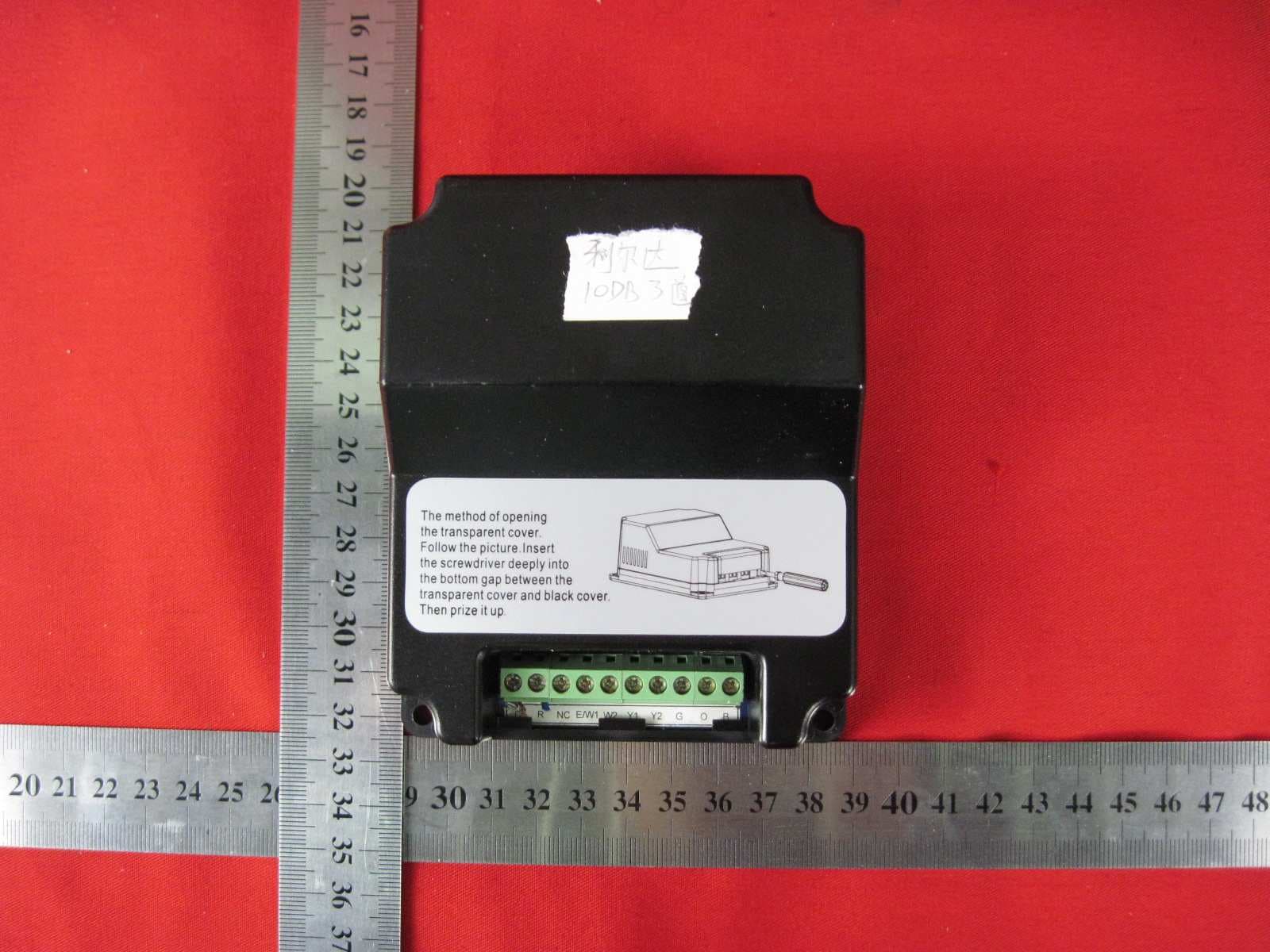
Click to zoom
Application Details
- Equipment Class
- DSR - Part 15 Remote Control/Security Device Transceiver
- Date of Grant
- Feb 20, 2011
- Application Purpose
- Original Equipment
- Date of Application
- Feb 14, 2011
- Equipment Note
- Wireless Thermostat
- Frequency Range
- 433.59400000 - 433.59400000
- Country
- China
Documents & Files
Document Text
Text extracted from the exhibit documents filed with the FCC. Open a document above to read the original.
Users Manual
RV01-W manual GENERAL The set is designed to control the room temperature in industrial, commercial and residential environments. It includes an A3900 and an RV01-W. Wireless data communication between the thermostat and controller enables temperature control. Read This Before Installing Controller OPERATION The RV01-W receives the signal from the Wireless Thermostat without any wires and controls the cooling and heating equipment. YOUR THERMOSTAT REPLACES Description Heat Pump (No Aux. or Emergency Heat) Yes Heat Pump (with Aux. or Emergency Heat) Yes Standard Heating & Cooling Systems Yes Two Stage Heating & Two Stage Cooling Yes Standard Heating Only Systems Yes Millivolt Heating Only Systems– Floor or Wall Furnaces Yes Standard Central Air Conditioning Yes Gas or Oil Heating Yes Electric Furnace Yes Hydronic (Hot Water) Zone Heat-2 Wires Yes Hydronic (Hot Water) Zone Heat–3 Wires No This Controller will NOT control 110/220Volt systems. POWER SUPPLY The RV01-W must be powered by 24 VAC. MATCHING The thermostat matched with the Controller at the factory. Simply Power up the Controller and operate the Thermostat. Follow the instructions below only if you find the Thermostat and Controller are not communicating. Step 1 Make sure the thermostat mode is in the OFF position. Step 2 Press “PROG” key for 3 seconds until the screen changes to the menu screen. Step 3 Press “PROG” key to scroll through the menu until the LCD displays ”CRES”. Step 4 Press the Matching Key on the controller. Step 5 Use the UP key on the thermostat to change the parameter ”CRES” to “1” immediately. The thermostat will force the controller to match. Press the Hold/Run Key to return to the normal screen. Step 6 Test by selecting Fan ON in the Thermostat screen. Wait for the radio signal icon to flash once on the screen. TESTING Similar to menu setting. Step 1 Press the “PROG” key, until it displays “TEST”, change the parameter to “2” by pressing the "up" key. The relays will open one by one. Step 2 Testing is finished, press the "RUN" key to exit the setting state. NOTE: This item is only for testing, not for normal output. If the wires are left connected this test may be dangerous. NOTE: The distance between the thermostat and controller should be longer than 1m, if not it may fail to communicate, requiring a return to the first step. In the event that the Thermostat and Controller haven't matched, press and hold the key on the right side of the controller for at least 3 seconds. Relays will open and close one by one. The program will exit testing after 3 cycles. This test can be terminated by pressing and holding the button on the side for 3 seconds. Technical Data Power AC24V±10%,50/60Hz Working environment 32°F~120°F ( 0°C~50°C ) Range 5~95%RH(non-condensing) Shell Fire retardant PC ABS Dimension 4.5x3.8x1.8 in ( 116×98×45 mm )(HxWxD) Connection interface Each terminal is capable of accepting 2×18 AWG solid copper wires Wireless carrier wave frequency 433MHz Communication baud rate 10kbps Wireless channels 1~6channels Communication distance Beeline distance 300ft in the field (The distance will reduce to 100ft if through walls and floors) COMPRESSOR PROTECTION The thermostat provides a 4 minutes delay after shutting off the heating or cooling system before it can be restarted. This delay will prevent damage to your compressor caused by rapid cycling. Note that this delay also applies to the heating system control. It does not provide a delay when there are power outages. You can select the function of "on" or "off" from the configuration. WIRELESS Modulation: GFSK WIRELESS Tx/Rx Datarate: 10KBaud WIRELESS Tx/Rx Deviation: 19KHZ WIRELESS CHANNEL Wireless Channel Communications Center Frequency Allowable Frequency Differences 1 433.594 MHZ ±30KHZ 2 433.794 MHZ ±30KHZ 3 433.994MHZ ±30KHZ 4 434.194 MHZ ±30KHZ 5 434.394 MHZ ±30KHZ 6 434.594 MHZ ±30KHZ THERMOSTAT OUTPUT Standard Terminal Outputs: Refer to equipment manufacturers' instructions for specific system wiring information. You can configure the controller for use with either multi-stage electric heat systems or multi-stage gas systems. When configured for electric heat, the G terminal (blower/fan) will be energized on a call for heat. This thermostat is designed to operate a single-transformer system. If you have a two-transformer system, cut and tape off one transformer. If the transformer safety circuits are in only one of the systems, remove the transformer of the system with NO safety circuits. If required, replace the remaining transformer with a 75VA Class II transformer. After disconnecting one transformer, the two commons must be connected together. Use the terminal output information below to help you wire the thermostat properly for your multi-stage system. After wiring see CONFIGURATION section for proper thermostat configuration. THERMOSTAT TERMINALS SYSTEM Single-stage Multi-stage C 24 Volt (Common) R 24 Volt Emergency (hot) E/W1 Heat mode 1st stage W2 No output Heat Mode 2nd stage Y1 Cool Mode 1st stage Y2 No output 2nd stage compressor G Blower/Fan Energized on call for Cool (and Heat if configured to Electric Heat) O No output B No output Heat Pump Terminal Outputs Refer to equipment manufacturers' instructions for specific system wiring information. You can configure the thermostat for use with the following heat pump system types: Single stage compressor system; gas or electric backup. This thermostat is designed to operate a single-transformer system. If you have a two-transformer system, cut and tape off one transformer. If transformer safety circuits are in only one of the systems, remove the transformer of the system with NO safety circuits. If required, replace remaining transformer with a 75VA Class II transformer. After disconnecting one transformer, the two commons must be connected together. Use the terminal output information below to help you wire the thermostat properly for your heat pump system. After wiring, see CONFIGURATION se…
Text truncated - open the document above for the full version.
External Photos
External Photos
ID Label/Location Info
Room Thermostat Model:RV01-W FCC ID:XLXRV01-W Power supply: 24Vac (±10%), 50Hz/60Hz Load: <1A Protection level: IP30 Environment requirement: Operation temperature 0 - 50°C Humidity range :5 - 95% RH(non-condensing) Beijing Hailin Auto Controls Equipment Co.,Ltd This device complies with part 15 of the FCC Rules. Operation is subject to the following two conditions: (1) This device may not cause harmful interference, and (2) this device must accept any interference received, including interference that may cause undesired operation.
Test Report
Figure 1: Mains terminal continuous disturbance voltage, line L Figure 2: Mains terminal continuous disturbance voltage, line N Figure 3: 20dB Bandwidth of the lowest frequency Figure 4: 20dB Bandwidth of the highest frequency Figure 5: 200ms pulse train plot Figure 6: Spectral diagrams and measurement results, Horizontal polarization, 30MHz-1GHz, 3m, the lowest frequency. Figure 7: Spectral diagrams and measurement results, Horizontal polarization, >1GHz, 3m, the lowest frequency. Figure 8: Spectral diagrams and measurement results, Vertical polarization, 30MHz-1GHz, 3m, the lowest frequency. Figure 9: Spectral diagrams and measurement results, Vertical polarization, >1GHz, 3m, the lowest frequency. - Figure 10: Spectral diagrams and measurement results, Horizontal polarization, 30MHz-1GHz, 3m, the highest frequency. Figure 11: Spectral diagrams and measurement results, Horizontal polarization, >1GHz, 3m, the highest frequency. Figure 12: Spectral diagrams and measurement results, Vertical polarization, 30MHz-1GHz, 3m, the highest frequency. Figure 13: Spectral diagrams and measurement results, Vertical polarization, >1GHz, 3m, the highest frequency. Figure 14: Duration of transmission
Test Report
Produkte Products Prüfbericht - Nr.: Test Report No.: 18000340 001 Seite 1 von 27 Page 1 of 27 Auftraggeber: Client: Beijing Hailin Electric Equipment Co., Ltd Shahe Industrial Zone, Changping District, Beijing 102206 P.R.China Gegenstand der Prüfung: Test item: Wireless Thermostat Bezeichnung: Identification: RV01-W Serien-Nr.: Serial No.: Engineering Sample Wareneingangs-Nr.: Receipt No.: 1143001493 Eingangsdatum: Date of receipt: 2009-06-22 Prüfort: Testing location: Refer to section 1.1 Prüfgrundlage: Test specification: FCC Part 15 Subpart C: 2009 Prüfergebnis: Test Result: Der Prüfgegenstand entspricht oben genannter Prüfgrundlage(n). The test items passed the test specification(s). Prüflaboratorium: Testing Laboratory: Refer to section 1.1 geprüft/ tested by: 2011-01-27 Yang, Kai/PE kontrolliert/ reviewed by: 2011-01-27 Sun, Lixun/TC Datum Date Name/Stellung Name/Position Unterschrift Signature Datum Date Name/Stellung Name/Position Unterschrift Signature Sonstiges/ Other Aspects: Abkürzungen: P(ass) = entspricht Prüfgrundlage F(ail) = entspricht nicht Prüfgrundlage N/A = nicht anwendbar N/T = nicht getestet Abbreviations: P(ass) = passed F(ail) = failed N/A = not applicable N/T = not tested Produkte Products Prüfbericht - Nr.: Test Report No.: 18000340 001 Seite 2 von 27 Page 2 of 27 TEST SUMMARY 4.1.1 SECTION 15.203 ANTENNA REQUIREMENT Result: Passed 4.1.2 SECTION 15.207 MAINS TERMINAL CONTINUOUS DISTURBANCE VOLTAGE Result: Passed 4.1.3 SECTION 15.231 (C) 20DB BANDWIDTH TESTING Result: Passed 4.1.4 SECTION 15.205, SECTION 15.209, SECTION 15.231 (B) RADIATED EMISSION Result: Passed 4.1.5 SECTION 15.231 (A) LIMITING OPERATIONS AND DURATION OF TRANSMISSION Produkte Products Prüfbericht - Nr.: Test Report No.: 18000340 001 Seite 3 von 27 Page 3 of 27 Contents 1 TEST SITES ..............................................................................................................................................................4 1.1 TEST FACILITIES..................................................................................................................................................4 1.2 LIST OF TEST AND MEASUREMENT INSTRUMENTS...............................................................................................4 2 GENERAL PRODUCT INFORMATION..............................................................................................................5 2.1 PRODUCT FUNCTION AND INTENDED USE............................................................................................................5 2.2 RATINGS AND SYSTEM DETAILS..........................................................................................................................5 2.3 INDEPENDENT OPERATION MODES......................................................................................................................5 2.4 NOISE GENERATING AND NOISE SUPPRESSING PARTS.........................................................................................5 2.5 SUBMITTED DOCUMENTS.....................................................................................................................................5 3 TEST SET-UP AND OPERATION MODES .........................................................................................................6 3.1 TEST SPECIFICATION............................................................................................................................................6 3.2 PRINCIPLE OF CONFIGURATION SELECTION.........................................................................................................6 3.3 PHYSICAL CONFIGURATION FOR TESTING............................................................................................................6 3.4 TEST OPERATION AND TEST SOFTWARE..............................................................................................................6 3.5 SPECIAL ACCESSORIES AND AUXILIARY EQUIPMENT..........................................................................................6 3.6 COUNTERMEASURES TO ACHIEVE EMC COMPLIANCE.........................................................................................6 4 SUMMARY OF TEST RESULTS...........................................................................................................................7 4.1 TEST RESULT.......................................................................................................................................................8 4.1.1 Section 15.203 Antenna Requirement..........................................................................................................8 4.1.2 Section 15.207 Mains Terminal Continuous Disturbance Voltage .............................................................9 4.1.3 Section 15.231 (c) 20dB Bandwidth Testing .............................................................................................12 4.1.4 Section 15.205, Section 15.209, Section 15.231 (b) Radiated Emission ...................................................14 4.1.5 Section 15.231 (a) Limiting operations and duration of transmission ......................................................24 5 PHOTOGRAPHS OF THE TEST SET-UP .........................................................................................................25 6 LIST OF TABLES ..................................................................................................................................................27 7 LIST OF FIGURES ................................................................................................................................................27 8 LIST OF PHOTOGRAPHS ...................................................................................................................................27 Produkte Products Prüfbericht - Nr.: Test Report No.: 18000340 001 Seite 4 von 27 Page 4 of 27 1 Test Sites 1.1 Test Facilities Laboratory: Audix Technology (Shenzhen) Co., Ltd. (2.94…
Text truncated - open the document above for the full version.
Test Setup Photos
Photograph 1: Set-up for mains terminal continuous disturbance voltage Photograph 2: Set-up for measurement of radiated emission, <1GHz Photograph 3: Set-up for measurement of radiated emission, >1GHz
Contact Information
Applicant
Yongming Huang(Testing Engineer)
Technical Contact
TUV Rheinland (China) Ltd.Kai Yang
[email protected]010-65666660
Unit 707, AVIC Bldg., No.10B, Central Road, · Beijing · China
Non-Technical Contact
TUV Rheinland (China) Ltd.Kai Yang
[email protected]010-65666660
Test Firm
Audix Technology (Shenzhen) Co.Smart Tsai
Technical Specifications
| # | Rule Parts | Frequency Range | Power Output |
|---|---|---|---|
| 1 | 15.231 | 433.594 MHz - 433.594 MHz | - |
Other Applications from Beijing HaiLin Auto Controls Equipment Co., Ltd.
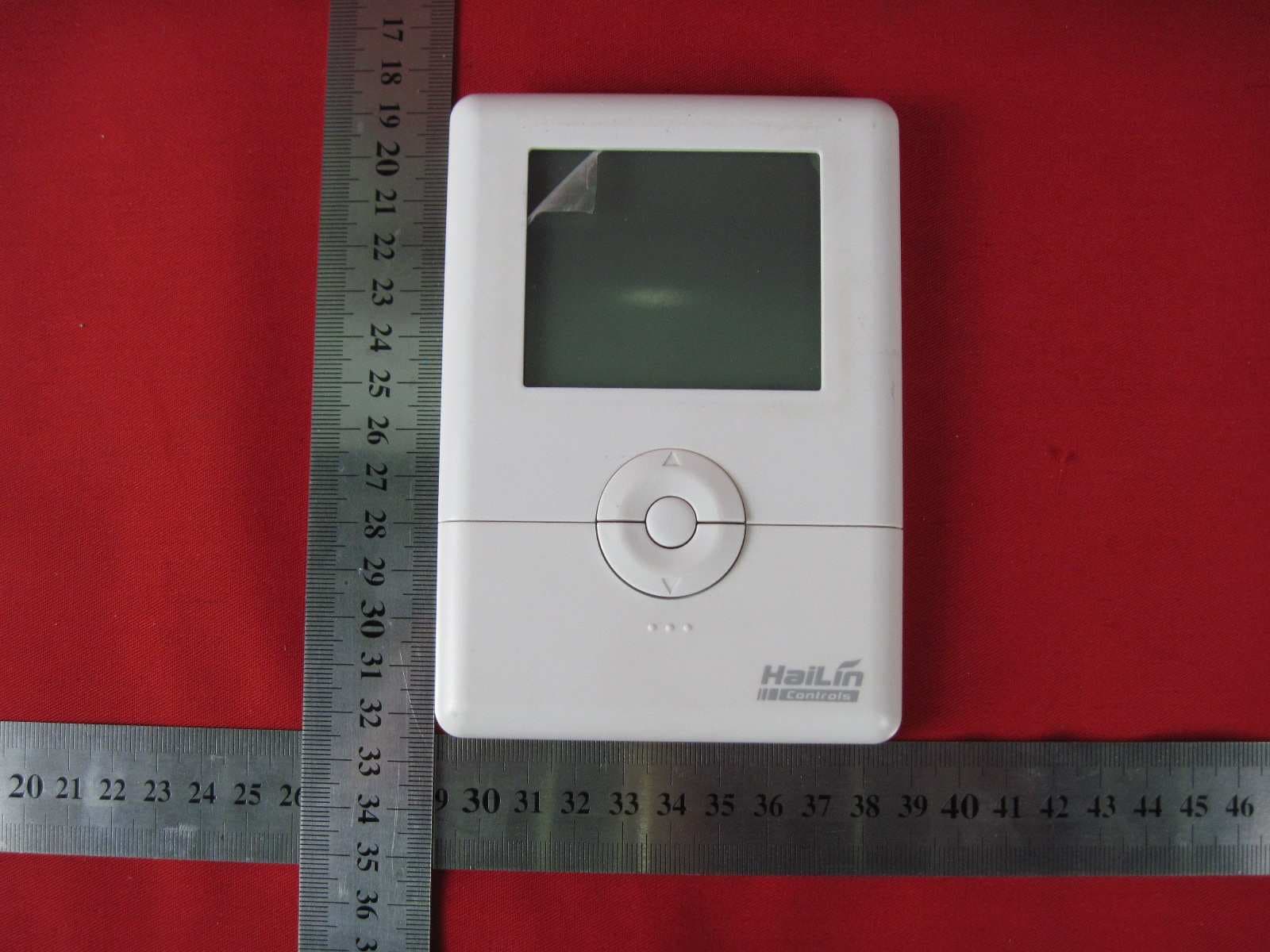
XLXA3900
Jan 11, 2011Wireless Thermostat
Equipment Class
DSR - Part 15 Remote Control/Security Device Transceiver