XM2-LOWPOWER6OPTICAL SYSTEMS
Teko Telecom Srl
Click to zoom
Application Details
- Equipment Class
- PCB - PCS Licensed Transmitter
- Date of Grant
- Aug 08, 2011
- Application Purpose
- Original Equipment
- Date of Application
- Aug 07, 2011
- Equipment Note
- OPTICAL SYSTEMS
- Frequency Range
- 940.00000000 - 941.00000000
- Company
- Teko Telecom Srl
- Country
- Italy
Documents & Files
Document Text
Text extracted from the exhibit documents filed with the FCC. Open a document above to read the original.
Users Manual
www.tekotelecom.it www.tekotelecom.it Let us repeat ! SIRIUS: Teko Telecom Modular Coverage and Capacity System TECHNICAL HANDBOOK Doc ID Number 91 080 0781 - Rel. 02 english www.tekotelecom.it www.tekotelecom.it Doc ID Number 91 080 0781 - Rel. 02 english Let us repeat ! BOLOGNA, 11/10/2010 UPDATINGS: Rel. 02 (11/04/2011) ......................................... ......................................... Document Identification Number 91 080 0781 – Rel. 02 SIRIUS: Teko Telecom Modular Coverage and Capacity System www.tekotelecom.it www.tekotelecom.it Doc ID Number 91 080 0781 - Rel. 02 page 3 english SIRIUS: Teko Telecom Modular Coverage and Capacity System Let us repeat ! Table of Contents 1. Teko Telecom Modular Coverage and Capacity System - General Description ...............9 1.1 Components ..........................................................................................................................10 1.1.1 Modules providing the RF interface towards the signal source ......................................12 1.1.2 Equipment extending coverage / distributing capacity .....................................................19 1.1.3 Modules providing the optical interface towards Remote Units ....................................22 1.1.4 Passive Modules providing distribution and filtering .........................................................29 1.1.5 Modules for the management of the System .........................................................................34 1.1.6 Power Supply Modules ...................................................................................................................39 1.1.7 Subracks hosting the System modules .....................................................................................41 1.1.8 Forced-air cooling Subrack ............................................................................................................43 1.2 Coverage and Capacity Solutions ......................................................................................44 1.2.1 Modular Off-air Repeaters - General description ..................................................................44 1.2.2 Optical Systems - General Description ......................................................................................47 A – Master Unit ...........................................................................................................................................47 B – Remote Units .......................................................................................................................................53 1.2.3 Coverage Systems Management and Power Supply ...........................................................61 1.2.4 Teko Telecom Coverage Systems Technical Specifications ................................................65 2. System Installation ...................................................................................................................68 2.1 Mechanical Installation .......................................................................................................69 2.1.1 Positioning Master Unit Subracks ...............................................................................................71 2.1.2 Positioning Remote Units ..............................................................................................................72 2.2 Connections ...........................................................................................................................74 2.2.1 RF Connections ..................................................................................................................................75 2.2.2 RS485 Connections ........................................................................................................................103 A – Connecting monitored subracks mounted within the same rack hosting the Master subrack ........................................................................................................................................104 B – Connecting remote monitored subracks ................................................................................105 2.2.3 Optical Connections ......................................................................................................................106 A – Connecting Master Unit to Remote Units ...............................................................................107 www.tekotelecom.it www.tekotelecom.it Doc ID Number 91 080 0781 - Rel. 02 page 4 english SIRIUS: Teko Telecom Modular Coverage and Capacity System Let us repeat ! B – Connecting Master point to point Modules to Slave point to point Modules ..........109 2.2.4 Power Supply Connections .........................................................................................................110 A – Active Subracks Power Supply Connection ...........................................................................111 B – Remote Units Power Supply Connection and Alarms Connection ................................114 2.3 Power-Up ..............................................................................................................................117 3. System Commissioning ..........................................................................................................119 4. Preventive Maintenance ........................................................................................................121 4.1 Optical Fibres .......................................................................................................................121 4.2 Remote Units .......................................................................................................................121 4.2.1 Remote Units with passive cooling system (natural convection - fan unit not equipped) ................................................................................................................................…
Text truncated - open the document above for the full version.
Cover Letter(s)
Teko Telecom S.p.A. Via Meucci, 24/a Castel S. Pietro Terme (BO) – Italy Tel +39 051 69 46 811 – Fax +39 051 94 84 73 P.IVA/VAT IT 02186561201 – Reg. Imprese di Bologna n. 02186561201 Capitale sociale Euro 660.000,00 i.v. – Soggetta a direzione e coordinamento di MetaSystem Group S.p.A. Società con Sistema di Qualità ed Ambiente certificato – ISO 9001:2000, ISO 14001:2004 Castel San Pietro Terme, 28 July 2011 Nemko Canada Inc 303 River Road Ottawa, Ontario, Canada K1V 1H2 Attn: Director of Certification Authority to Act as Agent On our behalf, I appoint Nemko Spa – via del Carroccio n. 4, Biassono (MB) Italy to act as our agent in the preparation of this application for equipment certification. I certify that submitted documents properly describe the device or system for which equipment certification is sought. I also certify that each unit manufactured, imported or marketed, as defined in the Federal Communications Commission’s regulations will have affixed to it a label identical to that submitted for approval with this application. For instances where our authorized agent signs the application for certification on our behalf, I acknowledge that all responsibility for complying with the terms and conditions for certification, as specified by Nemko Canada Inc, still resides with (applicant name and address). Dated 28 July 2011 By: ALESSANDRO BRUNELLI Signature Printed Title: CERTIFICATION ENGINEER On behalf of : TEKO TELECOM Telephone: +39 051 6946811
Cover Letter(s)
Teko Telecom S.p.A. Via Meucci, 24/a Castel S. Pietro Terme (BO) – Italy Tel +39 051 69 46 811 – Fax +39 051 94 84 73 P.IVA/VAT IT 02186561201 – Reg. Imprese di Bologna n. 02186561201 Capitale sociale Euro 660.000,00 i.v. – Soggetta a direzione e coordinamento di MetaSystem Group S.p.A. Società con Sistema di Qualità ed Ambiente certificato – ISO 9001:2000, ISO 14001:2004 Castel San Pietro Terme, 28 July 2011 Nemko Canada Inc. 303 River Road Ottawa, Ontario, Canada K1V 1H2 FCC ID: XM2-LOWPOWER6 Product Name: Optical Systems Remote Unit TRL7S8SC8A9S19AWAS with Master Device REUSE TEST REPORT The multiband low power units are engineered following a fully modular philosophy and thanks to this it will be possible to create every combination of bands reusing the same circuitry. Due to this design methodology every section (band amplifier) will have the exact RF schematics, PCB layout, component, RF level setup, modulation type and consequently RF performance for each frequency band and so this allow us the reuse of test data obtained during previous measuring sessions. External antenna is not provided with equipment. The bands were already tested in other projects except for a new band. Details are: SMR700: 698-787 MHz (see FCC ID: XM2LOWPOWERL, see test reports: 148253-1_TRFWL and 148253-2_TRFWL) SMR800C: 817-869 MHZ (new band) AMPS: 824-894 MHz (see FCC ID: XM2-LOWPOWER, see test reports: 131640-1_TRF_EMC and 156523-1_TRF_WL) SMR900: 896-940 and 901-941 MHz (see FCC ID: XM2LOWPOWERL) (see FCC ID: XM2LOWPOWERL, see test reports: 148253-3_TRFWL and 148253-4_TRFWL) PCS: 1850-1995 MHz (see FCC ID: XM2-LOWPOWER) (see FCC ID: XM2-LOWPOWER, see test reports: 131640-2_TRF_EMC and 156523-2_TRF_WL) AWS: 1710-2155 MHz (see FCC ID: XM2-LOWPOWER) (see FCC ID: XM2-LOWPOWER, see test reports: 131640-3_TRF_EMC and 156523-3_TRF_WL) Teko Telecom S.p.A. Via Meucci, 24/a Castel S. Pietro Terme (BO) – Italy Tel +39 051 69 46 811 – Fax +39 051 94 84 73 P.IVA/VAT IT 02186561201 – Reg. Imprese di Bologna n. 02186561201 Capitale sociale Euro 660.000,00 i.v. – Soggetta a direzione e coordinamento di MetaSystem Group S.p.A. Società con Sistema di Qualità ed Ambiente certificato – ISO 9001:2000, ISO 14001:2004 Dated 28 July 2011 By: ALESSANDRO BRUNELLI Signature Printed Title: CERTIFICATION ENGINEER On behalf of : TEKO TELECOM Telephone: +39 051 6946811
External Photos
TEKO TELECOM S.p.A. Via Meucci, 24/a 40024 Castel S. Pietro Terme (BO) – Italy Tel +39 051 69 46 811 – Fax +39 051 94 84 73 www.tekotelecom.it File: Teko - external photos.docx Pg.1 of 2 REMOTE UNIT TRL7S8SC8A9S19AWAS EXTERNAL PHOTOS TEKO TELECOM S.p.A. Via Meucci, 24/a 40024 Castel S. Pietro Terme (BO) – Italy Tel +39 051 69 46 811 – Fax +39 051 94 84 73 www.tekotelecom.it File: Teko - external photos.docx Pg.2 of 2
ID Label/Location Info
TEKO TELECOM S.p.A. Via Meucci, 24/a 40024 Castel S. Pietro Terme (BO) – Italy Tel +39 051 69 46 811 – Fax +39 051 94 84 73 www.tekotelecom.it File: Label.docx Pg.1 of 1 LABEL LOCATION AND LABEL CONTENT
Internal Photos
Teko Telecom S.p.A. Via Meucci, 24/a Castel S. Pietro Terme (BO) – Italy Tel +39 051 69 46 811 – Fax +39 051 94 84 73 P.IVA/VAT IT 02186561201 – Reg. Imprese di Bologna n. 02186561201 Capitale sociale Euro 660.000,00 i.v. – Soggetta a direzione e coordinamento di MetaSystem Group S.p.A. Società con Sistema di Qualità ed Ambiente certificato – ISO 9001:2000, ISO 14001:2004 INTERNAL COMPARATIVE PHOTOS INTERNAL PHOTO OF TRL7S8SC8A9S19AWAS In this image, each colour represents a different section (band amplifier) on the new equipment. In the photos below, that represent previous and already tested equipment, you can see the same section highlighted with the same colour of the photo above. The yellow section is the new one and it is included in the new disegned filter. Teko Telecom S.p.A. Via Meucci, 24/a Castel S. Pietro Terme (BO) – Italy Tel +39 051 69 46 811 – Fax +39 051 94 84 73 P.IVA/VAT IT 02186561201 – Reg. Imprese di Bologna n. 02186561201 Capitale sociale Euro 660.000,00 i.v. – Soggetta a direzione e coordinamento di MetaSystem Group S.p.A. Società con Sistema di Qualità ed Ambiente certificato – ISO 9001:2000, ISO 14001:2004 INTERNAL PHOTO OF TRU8A19AWWS/AC-WL INTERNAL PHOTO OF TRU7S8A19WL/AC-WS Teko Telecom S.p.A. Via Meucci, 24/a Castel S. Pietro Terme (BO) – Italy Tel +39 051 69 46 811 – Fax +39 051 94 84 73 P.IVA/VAT IT 02186561201 – Reg. Imprese di Bologna n. 02186561201 Capitale sociale Euro 660.000,00 i.v. – Soggetta a direzione e coordinamento di MetaSystem Group S.p.A. Società con Sistema di Qualità ed Ambiente certificato – ISO 9001:2000, ISO 14001:2004 INTERNAL PHOTO OF TRU8S9S19WL/AC-WS
Operational Description
www.tekotelecom.it www.tekotelecom.it Doc ID Number 91 080 0781 - Rel. 02 page 53 english SIRIUS: Teko Telecom Modular Coverage and Capacity System Let us repeat ! Remote UnitsB – Remote Units distribute wireless signals throughout the area to be covered ; they can be installed up to 20km (12.4miles) from the Master Unit site. Remote Units can be Single, Dual or Tri-band with different power classes: Very High, High, Medium and Low. Single, Dual or Tri-band Very High, High and Medium Power Remote Unit Single, Dual or Tri-band Low Power Remote Unit Remote Units are equipped with the Fiber Optic Receiver and Transmitter module (for Optical to RF and RF to Optical conversion) power amplifiers and filtering. A single Master Unit can drive up to 144 Remote Units. Various network structures can be supported by the Master Unit: the Remote Units of the same Optical System can be deployed with a point-to-point connection (star-configuration - using one fiber optic per Remote Unit) or with cascading of up to 5 Remote Units using a single fibre and optimized optical couplers. www.tekotelecom.it www.tekotelecom.it Doc ID Number 91 080 0781 - Rel. 02 page 54 english SIRIUS: Teko Telecom Modular Coverage and Capacity System Let us repeat ! The following figure shows the Tri-band Remote Unit block diagram: in down-link the optical signal from Master Unit is converted into an RF signal by the Fiber Optic Receiver module. RF signals, filtered by the triplexer, are amplified by Low, Medium, High or Very High Power amplifiers (Low, Medium, High or Very High Power Remote Units), filtered and transmitted through an antenna or a passive distribution system. In up-link the RF signal is filtered by the triplexer. The three RF signals are amplified by Low-Noise Amplifiers, filtered and then converted into an optical signal by the Fiber Optic Transmitter module. The signal is transmitted via fiber optics to the Master Unit. Fiber Optic Receiver From MASTER unit (DownLink) To MASTER unit (UpLink) PA900 PA1800 PA2100 Antenna System LNA900 LNA1800 LNA2100 Fiber Optic Transmitter Management module PSU O E O E Example: Tri-band Remote Unit block diagram Please Note: each final power amplifier is protected by a fuse. Very High Power/High Power/Medium Power final amplifiers fuse position and electrical rating Fuse 32V-7,5A HPA/MPA Fuse 32V-20A VHPA Fuse 32V-7,5A Low Power final amplifier fuse position and electrical rating The management module collects information relevant to the various modules. An RF modem allows data communication over fiber between Remote Unit and Master Unit. Let us repeat ! TEKO TELECOM OPTICAL SYSTEM - US BAndS www.tekotelecom.it REMOTE UNIT DRILLING TEMPLATE TRL7S8SC8A9S19AWAS 6-Band Low Power Remote Unit operating in the SMR700, SMR800 Commercial, AMPS850, SMR900, PCS1900 and AWS1721 bands, belongs to TEKO TELECOM Optical System, the most advanced cost- effective flexible Multi-Band and Multi-Operator solution for cellular cover- age and capacity distribution. TEKO TELECOM Low Power Remote Units have been expressly conceived for high quality of service and easy set-up: Automatic Gain Control (AGC) on the optical link with the Master Unit, • for constant gain independently from optical losses; Linear Power Amplifiers expressly designed for IMD reduction over the • entire bandwidth; Automatic Level Control (ALC) in the UL path independent for each • band, for maximum quality of service; RF Antenna Combiners expressly designed for Multi-Operator function-• ing, providing high insulation and low passive intermodulation (PIM); Wavelength Division Multiplexing (WDM) for Tx/Rx communications • with the Master Unit over the same optical fibre; Point-to-point and cascade connection with the Master Unit, for maxi-• mum flexibility of installation; Optical remote link up to 20 km (12.4 miles);• New and innovative mechanical design, for easy installation and pro-• fessional visual impact; Optional kit providing IP66 protection degree, for installation in harsh • environments. TEKO TELECOM Remote Units are available in a wide range of different executions as for: Single-Band – Multi-Band,• Operating frequencies from 380 to 2700MHz, complying with all the • most important international standards for Mobile Communications and Public Safety, Low – Medium – High – Very High Power classes.• They represent the ideal solution for cellular coverage extension and ca- pacity distribution in any indoor application, campuses, long tunnels as well as in several outdoor scenarios. TRL7S8SC8A9S19AWAS 6-BAND LOW POWER REMOTE UNIT REMOTE UNIT BLOCK DIAGRAM Fiber Optic Transmitter Antenna System From/To MASTER unit (DownLink/UpLink) Management module PSU O E POWER AMPLIFIERS O E LOW NOISE AMPLIFIERS WDM Fiber Optic Receiver 350 mm (13.78 in) 395 mm (15.55 in) 414 mm (16.30 in) 385 mm (15.16 in) Let us repeat ! Teko Telecom S.p.A. - [email protected] Via Meucci 24/a - 40024 Castel San Pietro Terme (BO) - Italy Tel. +39 051 6946811 - Fax +39 051 948473 Let us repeat ! Teko Telecom S.p.A. - [email protected] Via Meucci 24/a - 40024 Castel San Pietro Terme (BO) - Italy Tel. +39 051 6946811 - Fax +39 051 948473 www.tekotelecom.it DS TRL7S8SC8A9S19AWAS - Ed. 01 - 24/02/2011 TRL7S8SC8A9S19AWAS 6-BAND LOW POWER REMOTE UNIT Optical output power6dBm Optical connectorsSC-APC Fibre typeSingle mode SMR 9/125 Optical Link Budget10 dB (AGC) Nominal Optical Input Power+6 dBm up to –4 dBm RF connectorN (f) RF return loss13dB Operating Wavelength1550 nm ± 20 nm Operating temperature range-20°C up to +55°C (-4°F up to +131°F) CoolingPassive (natural convection) Power supply85÷264Vac (50-60Hz) (/AC version); -72 ÷ -36Vdc (/48 version) Power consumption150 W Dimensionsapprox 414 x 395 x 144 mm (24.41 x 16.34 x 10.24 in) (max volume - heat sinks, handles and connectors included) Weightapprox 19 Kg (41.9lbs) Degree of protectionIP32 (box) IP66 (with optional protection kit) 6-BAND LOW POWER REMOTE UNIT TRL7S8SC8A9S19AWAS 6-BAND MULTI-OPERATOR…
Text truncated - open the document above for the full version.
Parts List/Tune Up Info
Distinta-compo.txt |-----------------------------------------------------------------------------------------------|-------------| |Bill Of Materials for 0054130.sch on Tue Nov 02 10:49:09 2010 | | |-----------------------------------------------------------------------------------------------|-------------| |ITEM |Reference |VALUE | TEKO-CODE | |-----+-----------------------------------------------------------+-----------------------------|-------------| |1 |C11 |0,9pF | 05 051 0109 | |2 |C160 C791 |1.5pF | 05 051 0115 | |3 |C454 C485 |2.2pF | 05 051 0125 | |4 |C185 |3.3pF | 05 051 0135 | |5 |C165 C322 C328 C373 C378 C787 |3.9pF | 05 051 0140 | |6 |C31 C41-42 C213 C218 C516 C535 C637 C665 C882 C887 C927 |6.8pF | 05 051 0160 | | |C932 | | | |7 |C142 C350 C498-499 |TBD | | |8 |C7 C14 C57-58 C72 C79 C86 C89-90 C92-94 C98 C100 C112-113 |100nF | 05 041 0275 | | |C115 C125-126 C128 C205-207 C244-245 C257 C260 C266 C269 | | | | |C275 C318-320 C356-358 C393-394 C401-402 C409-410 C459 C461| | | | |C489-490 C502 C545 C553 C561 C594 C596 C598-599 C615 C654 | | | | |C657-658 C682 C685-686 C707 C717-731 C739 C763 C765 C781 | | | | |C810-811 C816 C836 C845 C852-853 C860-861 C869-870 C879-880| | | | |C923-925 C960-961 C968-969 C1030 | | | |9 |C1023 C1025 |10nF | 05 041 0220 | |10 |C1031-1032 |22nF | 05 041 0230 | |11 |C109 |0.2pF | 05 051 0100 | |12 |C284 |0.5pF | 05 051 0105 | |13 |C792 |1.5pF | 05 051 0115 | |14 |C786 |1.8pF | 05 051 0120 | |15 |C9 C13 C23-24 C32 C43 C74 C95 C133 C186 C197 C214 C219 C261|100pF | 05 051 0255 | | |C280 C323 C329 C345 C374 C379 C395-397 C403-405 C411 C449 | | | | |C451 C455 C486 C503 C517 C528 C536 C638 C666 C691 C699 C715| | | | |C766 C779 C788 C834 C854-856 C862-864 C871-873 C883 C888 | | | | |C904 C928 C933 C949 C962 C970-972 C982 C992 C1006 C1022 | | | | |C1024 | | | |16 |C424 C426 C430 C432 C434 C491-493 C734-738 C742-748 |10nF | 05 041 0220 | | |C751-758 C805 C812 C1015 C1018 | | | |17 |C114 C173 C522 C976 C986 C1000 |15pF | 05 041 0080 | |18 |C2 C77-78 C116 C149 C177 C189 C196 C285 C526-527 C705-706 |1nF | 05 041 0185 | | |C709-710 C980-981 C990-991 C1004-1005 | | | |19 |C796 |2.2pF | 05 051 0125 | |20 |C40 C515 C534 C795 |2.7pF | 05 051 0130 | |21 |C132 C174 C523 C977 C987 C1001 |22pF | 05 051 0195 | |22 |C80 C521 C632 C802 |4.7pF | 05 051 0145 | |23 |C8 C75-76 C101-102 C169 C175 C241 C243 C267 C276-277 C326 |47pF | 05 051 0235 | | |C382 C412-413 C524 C687 C689 C695 C697 C813 C963-964 C978 | | | | |C988 C1002 | | | |24 |C22 C29 C159 C164 C184 C208 C217 C321 C327 C372 C377 C636 |5.6pF | 05 051 0155 | | |C664 C881 C886 C926 C931 | | | |25 |C453 C484 |8.2pF | 05 051 0165 | |26 |C5 C34 C91 C179 C199-200 C242 C270 C514 C530 C533 C688 C696|TBD | | | |C704 C708 C996 C1007 C1011 | | | |27 |C289 C292 C296 C445 C448 |100nF | 05 041 0275 | |28 |C25 C33 C48 C61 C63 C73 C97 C198 C222-225 C227-231 C262-263|10nF | 05 041 0220 | | |C281 C306-307 C312-313 C335-336 C341-342 C363-364 C369-370 | | | | |C386 C417 C421 C428 C433 C507 C511 C529 C572 C574 C578 C580| | | | |C582 C584 C586-588 C592 C659 C692 C700 C771 C826 C895-896 | | | | |C901-902 C940-941 C946-947 C983 C993 C1008 | | | |29 |C44 C117 C134 C162 C167 C187 C215 C220 C324 C330 C375 C380 |1nF | 05 041 0185 | | |C456 C487 C518 C539 C639 C667 C784 C789 C884 C889 C929 C934| | | |30 |C1 |1uF | 05 041 0285 | |31 |C62 |6.8nF | 05 041 0210 | |32 |C30 C501 |0.5pF | 05 051 0105 | |33 |C500 |0.8pF | 05 051 0108 | |34 |C12 |TBD | | |35 |C290-291 C297-298 |180pF | 05 041 0145 | |36 |C37 C46 C237 C440 |0.8pF | 05 051 0108 | |37 |C35 |1.5pF | 05 051 0115 | |38 |C106 C124 |100nF | 05 041 0275 | |39 |C4 C18 C39 C53-55 C119 C122 C135 C143-144 C158 C170 C183 |100pF | 05 041 0130 | | |C190 C194-195 C203 C209-210 C314 C316 C347 C351-352 C354 | | | | |C538 C541-543 C549 C555 C641 C643 C649-652 C669 C671 | | | | |C677-680 C903 C915-916 C918-921 C948 | | | |40 |C127 |10nF | 05 041 0220 | |41 |C10 C20 C27 C56 C84-85 C87 C103-104 C108 C120 C136 C145 |1nF | 05 041 0185 | | |C171 C180 C191 C204 C211 C287 C294 C301 C317 C348 C355 C387| | | | |C389 C391 C398-399 C406-407 C414-415 C431 C446 C497 C504 | | | | |C537 C544 C550 C556-557 C564-565 C567 C575 C633 C642 C653 | | | | |C655 C670 C681 C683 C716 C749 C759 C764 C768 C780 C823 C835| | | | |C857-858 C865-866 C874-875 C907 C917 C922 C952 C965-966 | | | | |C973-974 C1019 | | | |42 |C438 |1pF | 05 051 0110 | |43 |C560 |2.2nF | 05 041 0200 | |44 |C3 C6 C47 C121 C137 C172 C192 C212 C254 C349 C450 C452 C458|22pF | 05 051 0195 | | |C465-466 C470-483 C644 C672 C909-913 C954-958 | | | |45 |C559 |4.7pF | 05 051 0145 | |46 |C15 C21 C82 C123 C161 C166 C178 C193 C252-253 C255 C259 |47pF | 05 051 0235 | | |C300 C315 C343 C346 C353 C371 C546-548 C551-552 C554 | | | |47 |C16-17 C36 C107 C234-236 C238 C437 C439 C443 C800 |TBD | | |48 |C566 C569 |22pF | 05 051 0195 | |49 |C19 |TBD | | |50 |C28 C111 C152 C226 C283 C418-420 C506 C583 C585 C589-591 |1uF | 05 041 0285 | | |C593 C635 C733 C740 C750 C760 C770 C806-807 C814 C825 | | | | |C1016-1017 C1020 | | | |51 |C463 |0.3pF | 05 051 0103 | |52 |C606 C609 C611 |0.5pF | 05 051 0105 | |53 |C462 C464 C605 C625 |0.8pF | 05 051 0108 | |54 |C110 |1.5pF | 05 051 0115 | |55 |C331 C337 C359 C365 C610 C624 |1.8pF | 05 051 0120 | |56 |C333 C339 C361 C367 C629 C821 C850 |10pF | 05 051 0170 | |57 |C628 C820 C849 |12pF | 05 051 0180 | |58 |C622 C630 C817 C822 C846 C851 |15pF | 05 051 0185 | |59 |C99 |1pF | 05 051 0110 | |60 |C286 C798 C840 |2.2pF | 05 051 0125 | |61 |C429 C614 C663 C703 C732 C741 C775-776 C830-831 |22pF | 05 051 0195 | |62 |C626 |3.3pF | 05 051 0135 | |63 |C627 C819 C848 |3.9pF | 05 051 0140 | |64 |C239 C308 C891 C897 C936 C942 |4.7pF | 05 051 0145 | |65 |C304 C310 C893 C899 C938 C944 |5.6pF | 05 051 0155 | |66 |C713 C761 C777 C832 |6.8pF | 05 051 0160 | |67 |C334 C340 C362 C368 |8.2pF | 05 051 0165 | |68 |C427 C714 C762 C778 C833 |820pF | 05 050 0205 | |69 |C305 C311 C436 C494-495 C577 C581 C600-604 C616-620 C799 |TBD | | | |C803-804 C841-843 C868 C876 C878 C894 C900 C9…
Text truncated - open the document above for the full version.
RF Exposure Info
Prediction of MPE limit at a given distance Equation from page 18 of OET Bulletin 65, Edition 97-01 where:S = power density P = power input to the antenna G = power gain of the antenna in the direction of interest relative to an isotropic radiator R = distance to the center of radiation of the antenna Maximum peak output power at antenna input terminal:38.00(dBm) Maximum peak output power at antenna input terminal:6400(mW) Antenna gain(maximum):16(dBi) Maximum antenna gain:39.81071706(numeric) Time Averaging:100(%) Prediction distance:145(cm) Prediction frequency:2000(MHz) MPE limit for uncontrolled exposure at prediction frequency:1.000(mW/cm^2) Power density at prediction frequency:0.964349(mW/cm^2) Margin of compliance:-0.2(dB) This equates to:9.643487136W/m^2 2 4R PG S π =
RF Exposure Info
Prediction of MPE limit at a given distance Equation from page 18 of OET Bulletin 65, Edition 97-01 where:S = power density P = power input to the antenna G = power gain of the antenna in the direction of interest relative to an isotropic radiator R = distance to the center of radiation of the antenna Maximum peak output power at antenna input terminal:38.00(dBm) Maximum peak output power at antenna input terminal:6400(mW) Antenna gain(maximum):16(dBi) Maximum antenna gain:39.81071706(numeric) Time Averaging:100(%) Prediction distance:190(cm) Prediction frequency:865(MHz) MPE limit for uncontrolled exposure at prediction frequency:0.577(mW/cm^2) Power density at prediction frequency:0.561646(mW/cm^2) Margin of compliance:-0.1(dB) This equates to:5.616463076W/m^2 2 4R PG S π =
RF Exposure Info
Prediction of MPE limit at a given distance Equation from page 18 of OET Bulletin 65, Edition 97-01 where:S = power density P = power input to the antenna G = power gain of the antenna in the direction of interest relative to an isotropic radiator R = distance to the center of radiation of the antenna Maximum peak output power at antenna input terminal:38.00(dBm) Maximum peak output power at antenna input terminal:6400(mW) Antenna gain(maximum):4.5(dBi) Maximum antenna gain:2.818382931(numeric) Time Averaging:100(%) Prediction distance:50(cm) Prediction frequency:865(MHz) MPE limit for uncontrolled exposure at prediction frequency:0.577(mW/cm^2) Power density at prediction frequency:0.574156(mW/cm^2) Margin of compliance:0.0(dB) This equates to:5.74156256W/m^2 2 4R PG S π =
RF Exposure Info
Prediction of MPE limit at a given distance Equation from page 18 of OET Bulletin 65, Edition 97-01 where:S = power density P = power input to the antenna G = power gain of the antenna in the direction of interest relative to an isotropic radiator R = distance to the center of radiation of the antenna Maximum peak output power at antenna input terminal:38.00(dBm) Maximum peak output power at antenna input terminal:6400(mW) Antenna gain(maximum):6.5(dBi) Maximum antenna gain:4.466835922(numeric) Time Averaging:100(%) Prediction distance:50(cm) Prediction frequency:2000(MHz) MPE limit for uncontrolled exposure at prediction frequency:1.000(mW/cm^2) Power density at prediction frequency:0.909976(mW/cm^2) Margin of compliance:-0.4(dB) This equates to:9.099763416W/m^2 2 4R PG S π =
Test Report
Nemko Test Report: 131640-2 Applicant: TEKO Telecom S.p.A. Via Meucci, 24/a I-40024 Castel S. Pietro Terme (BO) Equipment Under Test: (E.U.T.) TRU8A19AWWL/AC-WS ( + Master Unit composed by: SUB-TRX+TPSU/AC+TPSU/48+TSPV-R+TTRC4W-S) In Accordance With: CFR 47, Part 24, Subpart E Broadband PCS Repeaters Tested By: Nemko Italy S.p.A.. Via Carroccio, 4 I-20046 Biassono (Italy) TESTED BY: G. Curioni DATE: 18-25 September, 2009 APPROVED BY: P. Barbieri DATE: 28 September, 2009 Number of Pages: 79 Nemko Italy S.p.A. CFR 47, PART 24, SUBPART E BROADBAND PCS REPEATERS EQUIPMENT: I TRU8A19AWWL/AC-WS PROJECT NO.: 131640-2 Page 2 of 79 Table of Contents SECTION 1. SUMMARY OF TEST RESULTS 3 SECTION 2. GENERAL EQUIPMENT SPECIFICATION 5 SECTION 3. RF POWER OUTPUT 8 SECTION 4. OCCUPIED BANDWIDTH 13 SECTION 5. SPURIOUS EMISSIONS AT ANTENNA TERMINALS 30 SECTION 6. FIELD STRENGTH OF SPURIOUS 59 SECTION 7. FILTER FREQUENCY RESPONSE 61 SECTION 8. TEST EQUIPMENT LIST 633 SECTION 9. PHOTOS 655 ANNEX A - TEST DETAILS 7070 ANNEX B - TEST DIAGRAMS 766 Nemko Italy S.p.A. CFR 47, PART 24, SUBPART E BROADBAND PCS REPEATERS EQUIPMENT: I TRU8A19AWWL/AC-WS PROJECT NO.: 131640-2 Page 3 of 79 Section 1. Summary of Test Results Manufacturer: TEKO Telecom Model No.: TRU8A19AWWL/AC-WS Serial No.: 090569002 General: All measurements are traceable to national standards. These tests were conducted on a sample of the equipment for the purpose of demonstrating compliance with CFR 47, Part 24, Subpart E. New Submission Production Unit Class II Permissive Change Pre-Production Unit THIS TEST REPORT RELATES ONLY TO THE ITEM(S) TESTED. THE FOLLOWING DEVIATIONS FROM, ADDITIONS TO, OR EXCLUSIONS FROM THE TEST SPECIFICATIONS HAVE BEEN MADE. See “ Summary of Test Data”. Nemko S.p.A. authorizes the above named company to reproduce this report provided it is reproduced in its entirety and for use by the company’s employees only. Any use which a third party makes of this report, or any reliance on or decisions to be made based on it, are the responsibility of such third parties. Nemko S.p.A. accepts no responsibility for damages, if any, suffered by any third party as a result of decisions made or actions based on this report. This report applies only to the items tested. Nemko Italy S.p.A. CFR 47, PART 24, SUBPART E BROADBAND PCS REPEATERS EQUIPMENT: I TRU8A19AWWL/AC-WS PROJECT NO.: 131640-2 Page 4 of 79 Summary Of Test Data NAME OF TEST PARA. NO. SPEC. RESULT RF Power Output 24.232 100W Complies Occupied Bandwidth 2.1049 Input/Output Complies Spurious Emissions at Antenna Terminals 24.238(a) -13 dBm Complies Field Strength of Spurious Emissions 24.238(a) -13 dBm erp Complies Frequency Stability 24.235 NA Footnotes For N/A’s: Frequency Stability testing was not per…
Text truncated - open the document above for the full version.
Contact Information
Applicant
Alessandro Brunelli(Certification Engineer)
Technical Contact
TEKO TELECOMMASSIMO NOTARGIACOMO
[email protected]+39 051 6946811
VIA MEUCCI 24/A · CASTEL SAN PIETRO TERME · Italy
Non-Technical Contact
TEKO TELECOMMARCO DELLA MORA
[email protected]+39 051 6946811
Test Firm
Nemko SpARalph Spanevello
Technical Specifications
| # | Rule Parts | Frequency Range | Power Output | Emission | Tolerance |
|---|---|---|---|---|---|
| 1 | 24D | 940 MHz - 941 MHz | 800.00 mW | D7W | Amp |
Other Applications from Teko Telecom Srl
XM2-RD35B35TW2
Mar 27, 2024Dual Band Next Generation Very Very High Power Remote Unit 3450-3550 and 3700-3980
Equipment Class
B2I - Part 20 Industrial Booster (CMRS)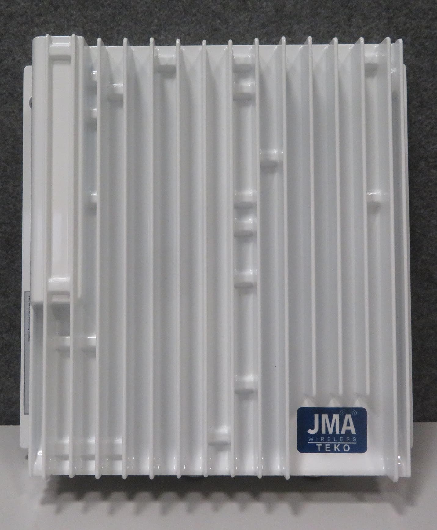
XM2-MP35B35B
Apr 02, 2023Remote Unit -Medium Power- 3450-3550 MHz
Equipment Class
B2I - Part 20 Industrial Booster (CMRS)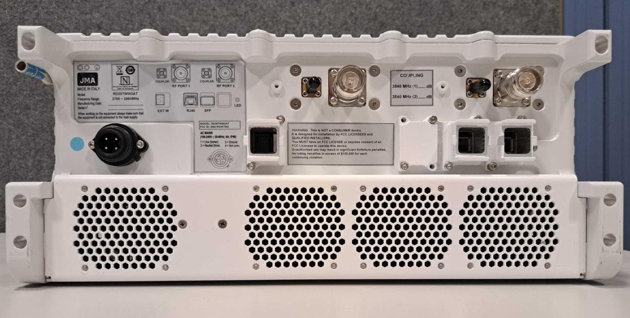
XM2-RD35TW2
Mar 27, 2023Next Generation Very Very High Power Remote Unit
Equipment Class
B2I - Part 20 Industrial Booster (CMRS)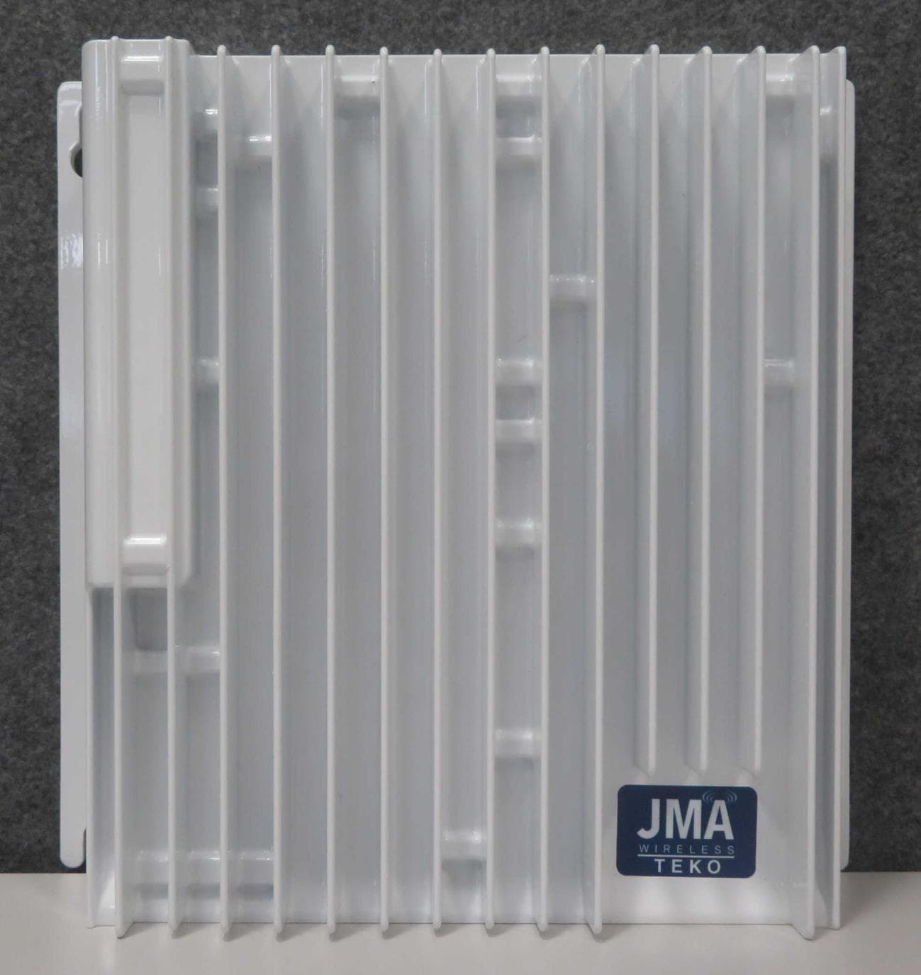
XM2-X25H2
Aug 03, 2022Cellhub High Power Radio Remote Unit
Equipment Class
TNB - Licensed Non-Broadcast Station Transmitter
XM2-X35H2B
Nov 02, 2020Cell Hub High-power Radio Remote Unit
Equipment Class
CBD - Citizens Band Category A and B Devices