XMR201404UC15UMTS/HSDPA Module
Quectel Wireless Solutions Company Limited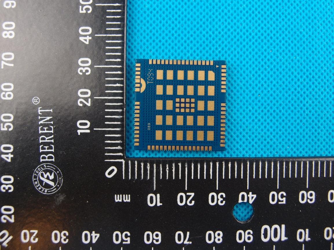
Click to zoom
Application Details
- Equipment Class
- PCB - PCS Licensed Transmitter
- Date of Grant
- May 28, 2014
- Application Purpose
- Original Equipment
- Date of Application
- May 28, 2014
- Equipment Note
- UMTS/HSDPA Module
- Frequency Range
- 1852.40000000 - 1907.60000000
- Country
- China
Documents & Files
Document Text
Text extracted from the exhibit documents filed with the FCC. Open a document above to read the original.
Users Manual
UC15 Hardware Design UMTS/HSDPA Module Series Rev. UC15_Hardware_Design_V1.3 Date: 2014-04-15 www.quectel.com UMTS/HSDPA Module Series UC15 Hardware Design UC15_Hardware_Design Confidential / Released 1 / 78 Our aim is to provide customers with timely and comprehensive service. For any assistance, please contact our company headquarters: Quectel Wireless Solutions Co., Ltd. Office 501, Building 13, No.99, Tianzhou Road, Shanghai, China, 200233 Tel: +86 21 5108 6236 Mail: [email protected] Or our local office, for more information, please visit: http://www.quectel.com/support/salesupport.aspx For technical support, to report documentation errors, please visit: http://www.quectel.com/support/techsupport.aspx GENERAL NOTES QUECTEL OFFERS THIS INFORMATION AS A SERVICE TO ITS CUSTOMERS. THE INFORMATION PROVIDED IS BASED UPON CUSTOMERS’ REQUIREMENTS. QUECTEL MAKES EVERY EFFORT TO ENSURE THE QUALITY OF THE INFORMATION IT MAKES AVAILABLE. QUECTEL DOES NOT MAKE ANY WARRANTY AS TO THE INFORMATION CONTAINED HEREIN, AND DOES NOT ACCEPT ANY LIABILITY FOR ANY INJURY, LOSS OR DAMAGE OF ANY KIND INCURRED BY USE OF OR RELIANCE UPON THE INFORMATION. THE INFORMATION SUPPLIED HEREIN IS SUBJECT TO CHANGE WITHOUT PRIOR NOTICE. COPYRIGHT THIS INFORMATION CONTAINED HERE IS PROPRIETARY TECHNICAL INFORMATION OF QUECTEL CO., LTD. TRANSMITTABLE, REPRODUCTION, DISSEMINATION AND EDITING OF THIS DOCUMENT AS WELL AS UTILIZATION OF THIS CONTENTS ARE FORBIDDEN WITHOUT PERMISSION. OFFENDERS WILL BE HELD LIABLE FOR PAYMENT OF DAMAGES. ALL RIGHTS ARE RESERVED IN THE EVENT OF A PATENT GRANT OR REGISTRATION OF A UTILITY MODEL OR DESIGN. Copyright © Quectel Wireless Solutions Co., Ltd. 2014. All rights reserved. UMTS/HSDPA Module Series UC15 Hardware Design UC15_Hardware_Design Confidential / Released 2 / 78 About the Document History Revision Date Author Description 1.0 2013-11-26 Mountain ZHOU Initial 1.1 2014-01-15 Huik LI 1. Modified packaging information of UC15 in the Chapter 7.3. 2. Modified Figure 4 and Figure 11. 3. Modified the description of command AT+CFUN in the Chapter 3.5.2. 1.2 2014-02-14 Huik LI Modified the frequency bands of UC15. 1.3 2014-04-15 Huik LI 1. Modified current consumption in Chapter 5.4. 2. Added PCM feature in Chapter 3.12. UMTS/HSDPA Module Series UC15 Hardware Design UC15_Hardware_Design Confidential / Released 3 / 78 Contents About the Document ................................................................................................................................... 2 Contents ....................................................................................................................................................... 3 Table Index ................................................................................................................................................... 6 Figure Index ................................................................................................................................................. 7 1 Introduction .......................................................................................................................................... 9 1.1. Safety Information...................................................................................................................... 9 2 Product Concept ................................................................................................................................ 11 2.1. General Description ................................................................................................................. 11 2.2. Directives and Standards ......................................................................................................... 12 2.2.1. FCC Statement ............................................................................................................... 12 2.2.2. FCC Radiation Exposure Statement .............................................................................. 12 2.3. Key Features ........................................................................................................................... 12 2.4. Functional Diagram ................................................................................................................. 15 2.5. Evaluation Board ..................................................................................................................... 15 3 Application Interface ......................................................................................................................... 17 3.1. General Description ................................................................................................................. 17 3.2. Pin Assignment ........................................................................................................................ 18 3.3. Pin Description ......................................................................................................................... 19 3.4. Operating Modes ..................................................................................................................... 24 3.5. Power Saving ........................................................................................................................... 25 3.5.1. Sleep Mode .................................................................................................................... 25 3.5.1.1. UART Application ................................................................................................. 25 3.5.1.2. USB Application with Suspend Function ............................................................. 26 3.5.1.3. USB Application without Suspend Function ........................................................ 27 3.5.2. Minimum Functionality Mode ......................................................................................... 27 3.6. Power Supply ................................................................................…
Text truncated - open the document above for the full version.
Cover Letter(s)
THIS MUST BE SIGNED BY THE APPLICANT AND SHOULD BE PLACED ON APPLICANTS LETTERHEAD ONLY IF AGENT IS SUBMITTING APPLICATION 022311 – 6 Authority to Act as Agent Date: _2014/5/19 American Certification Body, Inc. 6731 Whittier Avenue Suite C110 McLean, VA 22101 To Whom It May Concern: East China Institute of Telecommunications / Tina Gong_ is authorized to act on our behalf, until otherwise notified, for applications to American Certification Body, Inc. (ACB). We certify that we are not subject to denial of federal benefits, that includes FCC benefits, pursuant to Section 5301 of the Anti-Drug Abuse Act of 1988, 21 U.S.C. 862. Further, no party, as defined in 47 CFR 1.2002 (b), to the application is subject to denial of federal benefits, that includes FCC benefits. Thank you, Agency Agreement Expiration Date: ____12 months_____ By: (Signature 1 ) (Print name) Johnny xiang Title: Certification Manager On behalf of: Quectel Wireless Solutions Co. Ltd (Company Name) Telephone: 86-21-51086236 1 - Must be signed by applicant contact given for applicant on the FCC site, or by the authorized agent if an appropriate authorized agent letter has been provided. Letters should be placed on appropriate letterhead.
Cover Letter(s)
THIS MUST BE SIGNED BY THE APPLICANT/AGENT AND SHOULD BE PLACED ON APPROPRIATE LETTERHEAD 022311 – 6 Request for Confidentiality Date: 2014/5/19 Subject: Confidentiality Request for: XMR201404UC15 ______ Pursuant to FCC 47 CRF 0.457(d) and 0.459 and IC RSP-100, Section 10, the applicant requests that a part of the subject FCC application be held confidential. Type of Confidentiality Requested Exhibit Short Term Permanent Block Diagrams Short Term External Photos Short Term Permanent* 2 Internal Photos Short Term Permanent Operation Description/Theory of Operation Short Term Permanent Parts List & Placement/BOM Short Term Permanent Tune-Up Procedure Short Term Permanent Schematics Short Term Test Setup Photos Short Term Permanent* User’s Manual *Note: ______(Insert Explanation as Necessary)______ Quectel Wireless Solutions Co. Ltd has spent substantial effort in developing this product and it is one of the first of its kind in industry. Having the subject information easily available to "competition" would negate the advantage they have achieved by developing this product. Not protecting the details of the design will result in financial hardship. Permanent Confidentiality: The applicant requests the exhibits listed above as permanently confidential be permanently withheld from public review due to materials that contain trade secrets and proprietary information not customarily released to the public. Short-Term Confidentiality: The applicant requests the exhibits selected above as short term confidential be withheld from public view for a period of ___(specify number of days not to exceed 180) 3 ___ days from the date of the Grant of Equipment Authorization and prior to marketing. This is to avoid premature release of sensitive information prior to marketing or release of the product to the public. Applicant is also aware that they are responsible to notify ACB in the event information regarding the product or the product is made available to the public. ACB will then release the documents listed above for public disclosure pursuant to FCC Public Notice DA 04-1705. NOTE for Industry Canada Applications: The applicant understands that until such time that IC distinguishes between Short Term and Permanent Confidentiality, either type of marked exhibit above will simply be marked Confidential when submitted to IC. Sincerely, By: _ ___ Johnny xiang (Signature/Title 4 ) (Print name) 2 - The asterisked items (*) require further justification before permanent confidentiality will be allowed. These also currently require review by the FCC under their Permit-But-Ask policy before the grant is issued and can delay completion of an application. Further justification should be added to the note above. One such example for a potted device would be: “The EUT is FULLY potted using a non-removable epoxy based material. Removal of potting material causes irreparable damage to internal circuitry. See photographs exhibits that outline the device before and after potting.” 3 - Please refer to http://acbcert.com/documents/misc-docs/Memo-Short-Term-Vs-Standard-Confidentiality.pdf for complete details. 4 - Must be signed by applicant contact given for applicant on the FCC site, or by the authorized agent if an appropriate authorized agent letter has been provided. Letters should be placed on appropriate letterhead.
Cover Letter(s)
Cover Letter Date: May 19 th , 2014 American Certification Body, Inc. 6731 Whittier Avenue Suite C110 McLean, VA 22101 FCC ID: XMR201404UC15 Request Modular Authority We hereby request Modular Approval based on the numbered requirements identified below as we address them to be included in our application for equipment authorization. 1. The modular transmitter must have its own RF shielding. This is intended to ensure that the module does not have to rely upon the shielding provided by the device into which it is installed in order for all modular transmitter emissions to comply with Part15 limits. It is also intended to prevent coupling between the RF circuitry of the module and any wires or circuits in the device into which the module is installed. Such coupling may result in non-compliant operation. Response: The UC15 module meets this requirement by the use of an RF shield which encases power amplifier, PA, filters and all other RF components. The chipset, oscillators, and associated circuitry are entirely resident under a continuous metal shield assembly, designed for EMI mitigation, with designated ground and interfaces. Please reference device photos supplied with the document package for shield placement and assembly. 2. The modular transmitter must have buffered modulation/data inputs (if such inputs are provided) to ensure that the module will comply with Part 15 requirements under conditions of excessive data rates or over-modulation. Response: The modulation/data inputs are buffered, and routed through the baseband signal processor QSC6270 which inherently prevents non-compatible data rates or modulation types from being introduced to the transmitter. 3. The modular transmitter must have its own power supply regulation. This is intended to ensure that the module will comply with Part 15 requirements regardless of the design of the power supplying circuitry in the device into which the module is installed. Response: The transmitter module has its own dedicated power supply regulation, it is a linear regulator which buffers the UC15 DC voltage from the power supply voltage of the unit in which it is installed, thereby ensuring that the EMI emissions of the UC15 module are independent and unaffected by the device in which it is installed. 4. The modular transmitter must comply with the antenna requirements of Section 15.203 and 15.204(c). The antenna must either be permanently attached or employ a "unique" antenna coupler (at all connections between the module and the antenna, including the cable). Any antenna used with the module must be approved with the module, either at the time of initial authorization or through a Class n permissive change. The "professional installation" provision of Section 15.203 may not be applied to modules. Response: The UC15 module has two antenna connector, this module requires a unique coaxial feed assembly direct to the external antenna, which is approved for use as required in the relevant Sections and will be tested to confirm to FCC limits. 5. The modular transmitter must be tested in a stand-alone configuration, i.e., the module must not be inside another device during testing for compliance with Part 15 requirements. Response: Test in a stand-alone configuration and found compliant. Please refer to test report for compliance details. 6. The modular transmitter must be equipped with either a permanently affixed label or must be capable of electronically displaying its FCC identification number. Response: The module is equipped with a permanently affixed FCC ID label. Reference the label document showing label location on the module. Reference the User manual which states: "When integrating the module into a host, the label must be visible through a window, visible through an access panel that is easily removed, or a second label must be placed on the outside of the host device that contains the following text: Contains FCC ID: XMR201404UC15.” 7. The modular transmitter must comply with any specific rules or operating requirements that ordinarily apply to a complete transmitter and the manufacturer must provide adequate instructions along with the module to explain any such requirements. A copy of these instructions must be included in the application for equipment authorization. Response: Complies with rules and requirements that apply to a complete transmitter. Detailed instructions for maintaining compliance are given in the User’s Manual. 8. The modular transmitter must comply with any applicable RF exposure requirements in its final configuration. Response: The final configuration modular transmitter is compliant with applicable RF exposure requirements. The module will only be integrated into other authorized devices. RF Exposure is addressed in the RF Exposure Compliance. Thank you for your attention and timely review. Sincerely, Johnny xiang Certification Manager
External Photos
External photo:
ID Label/Location Info
Label&Location:
Internal Photos
Internal photo
RF Exposure Info
TEST REPORT No. 2014SAR0061 For Client : Quectel Wireless Solutions Co. Ltd Production : UMTS/HSDPA module Model Name : UC15 FCC ID: XMR201404UC15 Hardware Version: R1.0 Software Version: UC15AQAR02A01E1G Issued date: 2014-05-16 Note: The test results in this test report relate only to the devices specified in this report. This report shall not be reproduced except in full without the written approval of ECIT Shanghai. Test Laboratory: ECIT Shanghai, East China Institute of Telecommunications Add: 7F, G Area, No.668, Beijing East Road, Huangpu District, Shanghai, P. R. China Tel: (+86)-021-63843300, E-Mail: [email protected] SAR Test Report Report No.: 2014SAR0061 East China Institute of Telecommunications Page Number : 2 of 12 TEL: +86 21 63843300FAX:+86 21 63843301 Report Issued Date :May 16, 2014 Revision Version Report Number Revision Date Memo 2014SAR0061 00 2014-05-16 Initial creation of test report SAR Test Report Report No.: 2014SAR0061 East China Institute of Telecommunications Page Number : 3 of 12 TEL: +86 21 63843300FAX:+86 21 63843301 Report Issued Date :May 16, 2014 CONTENTS 1. TEST LABORATORY ........................................................................................................................ 4 1.1. TESTING LOCATION ........................................................................................................................ 4 1.2. TESTING ENVIRONMENT ............................................................................................................... 4 1.3. PROJECT DATA .................................................................................................................................. 4 1.4. SIGNATURE ......................................................................................................................................... 4 2. CLIENT INFORMATION ................................................................................................................... 5 2.1. APPLICANT INFORMATION ........................................................................................................... 5 2.2. MANUFACTURER INFORMATION ................................................................................................ 5 3. EQUIPMENT UNDER TEST (EUT) AND ANCILLARY EQUIPMENT (AE) ............................. 6 3.1. ABOUT EUT ......................................................................................................................................... 6 3.2. INTERNAL IDENTIFICATION OF EUT USED DURING THE TEST ........................................ 6 3.3. INTERNAL IDENTIFICATION OF AE USED DURING THE TEST ........................................... 6 4. REFERENCE DOCUMENTS ............................................................................................................. 7 4.1. APPLICABLE STANDARDS .............................................................................................................. 7 4.2. TEST LIMITS ....................................................................................................................................... 7 5. TEST RESULTS ................................................................................................................................... 8 5.1. CONDUCTED RF POWER OUTPUT ............................................................................................... 8 5.2. CALCULATION INFORMATION .................................................................................................. 10 5.3. RESULT OF GSM835 ......................................................................................................................... 11 5.4. RESULT OF GSM1900 ....................................................................................................................... 11 5.5. RESULT OF WCDMA BAND II ....................................................................................................... 12 5.6. RESULT OF WCDMA BAND V ....................................................................................................... 12 SAR Test Report Report No.: 2014SAR0061 East China Institute of Telecommunications Page Number : 4 of 12 TEL: +86 21 63843300FAX:+86 21 63843301 Report Issued Date :May 16, 2014 1. Test Laboratory 1.1. Testing Location Company Name: ECIT Shanghai, East China Institute of Telecommunications Address: 7-8F, G Area,No. 668, Beijing East Road, Huangpu District, Shanghai, P. R. China Postal Code: 200001 Telephone: (+86)-021-63843300 Fax: (+86)-021-63843301 FCC Registration NO.: 489729 1.2. Testing Environment NormalTemperature: 15-35°C Relative Humidity: 20-75% Ambient noise & Reflection: < 0.012 W/kg 1.3. Project Data Project Leader: Gong Yujuan Testing Start Date: 2014-05-14 Testing End Date: 2014-05-15 1.4. Signature SAR Test Report Report No.: 2014SAR0061 East China Institute of Telecommunications Page Number : 5 of 12 TEL: +86 21 63843300FAX:+86 21 63843301 Report Issued Date :May 16, 2014 2. Client Information 2.1. Applicant Information Company Name: Quectel Wireless Solutions Co. Ltd Address /Post: Room 501, Building 13, No.99 Tianzhou Road, Xuhui District, Shanghai,China Country: China Telephone: +86-21-51086236 Postal Code: 200233 Contact Hu Zhiqin 2.2. Manufacturer Information Company Name: Quectel Wireless Solutions Co. Ltd Address /Post: Room 501, Building 13, No.99 Tianzhou Road, Xuhui District, Shanghai,China Country: China Telephone: +86-21-51086236 Postal Code: 200233 Contact Hu Zhiqin SAR Test Report Report No.: 2014SAR0061 East China Institute of Telecommunications Page Number : 6 of 12 TEL: +86 21 63843300FAX:+86 21 63843301 Report Issued Date :May 16, 2014 3. Equipment Under Test (EUT) and Ancillary Equipment (AE) 3.1. About EUT EUT Description UMTS/HSDPA module Model name UC15 GSM Frequency Band GSM835/GSM1900 WCDMA Frequency Band WCDMA band II/WCDMA band V Antenna Type External Antenna FCC ID: XMR201404UC15 Note: Photographs of EUT are shown in ANNEX A of…
Text truncated - open the document above for the full version.
Test Report
TEST REPORT No. 2014RFA0061 For Client : Quectel Wireless Solutions Co. Ltd Production : UMTS/HSDPA module Model Name : UC15 FCC ID: XMR201404UC15 Hardware Version: R1.0 Software Version: UC15AQAR02A01E1G Issued date: 2014-05-20 Note: The test results in this test report relate only to the devices specified in this report. This report shall not be reproduced except in full without the written approval of ECIT Shanghai. Test Laboratory: ECIT Shanghai, East China Institute of Telecommunications Add: 7-8F, G Area, No.668, Beijing East Road, Huangpu District, Shanghai, P. R. China Tel: (+86)-021-63843300, E-Mail: [email protected] RF Test Report Report No.: 2014RFA0061 East China Institute of Telecommunications Page Number : 2 of 82 TEL: +86 21 63843300 FAX: +86 21 63843301 Report Issued Date : May 20, 2014 Revision Version Report Number Revision Date Memo 2014RFA0061 00 2014-05-20 Initial creation of test report RF Test Report Report No.: 2014RFA0061 East China Institute of Telecommunications Page Number : 3 of 82 TEL: +86 21 63843300 FAX: +86 21 63843301 Report Issued Date : May 20, 2014 CONTENTS 1. TEST LABORATORY ............................................................................................................... 5 1.1. TESTING LOCATION ............................................................................................................... 5 1.2. TESTING ENVIRONMENT ....................................................................................................... 5 1.3. PROJECT DATA ....................................................................................................................... 5 1.4. SIGNATURE ............................................................................................................................. 5 2. CLIENT INFORMATION ........................................................................................................... 6 2.1. APPLICANT INFORMATION ................................................................................................... 6 2.2. MANUFACTURER INFORMATION ......................................................................................... 6 3. EQUIPMENT UNDER TEST (EUT) AND ANCILLARY EQUIPMENT (AE) ............................ 7 3.1. ABOUT EUT ............................................................................................................................. 7 3.2. INTERNAL IDENTIFICATION OF EUT USED DURING THE TEST ....................................... 7 3.3. INTERNAL IDENTIFICATION OF AE USED DURING THE TEST ......................................... 7 3.4. STATEMENTS........................................................................................................................... 7 4. REFERENCE DOCUMENTS .................................................................................................... 8 4.1. REFERENCE DOCUMENTS FOR TESTING .......................................................................... 8 5. SUMMARY OF TEST RESULTS .............................................................................................. 9 6. TEST EQUIPMENTS UTILIZED ............................................................................................. 10 7. TEST ENVIRONMENT ........................................................................................................... 13 ANNEX A. MEASUREMENT RESULTS .................................................................................... 15 ANNEX A.1. OUTPUT POWER (§22.913(A)/§24.232(C)) ........................................................... 15 ANNEX A.2. 99%OCCUPIED BANDWIDTH (§2.1049(H)(I)) ....................................................... 17 ANNEX A.3. -26DB EMISSION BANDWIDTH(§22.917(B)/§24.238(B)) ..................................... 30 ANNEX A.4. BAND EDGE AT ANTENNA TERMINALS(§22.917(B)/§24.238(B)) ...................... 41 ANNEX A.5. FREQUENCY STABILITY (§2.1055/§24.235) ......................................................... 48 ANNEX A.6. CONDUCTED SPURIOUS EMISSION .................................................................... 54 RF Test Report Report No.: 2014RFA0061 East China Institute of Telecommunications Page Number : 4 of 82 TEL: +86 21 63843300 FAX: +86 21 63843301 Report Issued Date : May 20, 2014 ANNEX A.7. RADIATED................................................................................................................ 69 ANNEX A.8 CONDUCTED EMISSION (§15.107§15.207) .............................................................. 81 ANNEX B. DEVIATIONS FROM PRESCRIBED TEST METHODS .......................................... 82 RF Test Report Report No.: 2014RFA0061 East China Institute of Telecommunications Page Number : 5 of 82 TEL: +86 21 63843300 FAX: +86 21 63843301 Report Issued Date : May 20, 2014 1. Test Laboratory 1.1. Testing Location Company Name: ECIT Shanghai, East China Institute of Telecommunications Address: 7-8F, G Area, No. 668, Beijing East Road, Huangpu District, Shanghai, P. R. China Postal Code: 200001 Telephone: (+86)-021-63843300 Fax: (+86)-021-63843301 FCC Registration NO.: 489729 1.2. Testing Environment Normal Temperature: 15-35°C Extreme Temperature: -10/+55°C Relative Humidity: 30-60% 1.3. Project data Project Leader: Gong Yujuan Testing Start Date: 2014-05-05 Testing End Date: 2014-05-07 1.4. Signature RF Test Report Report No.: 2014RFA0061 East China Institute of Telecommunications Page Number : 6 of 82 TEL: +86 21 63843300 FAX: +86 21 63843301 Report Issued Date : May 20, 2014 2. Client Information 2.1. Applicant Information Company Name: Quectel Wireless Solutions Co. Ltd Address: Room 501, Building 13, No.99 Tianzhou Road, Xuhui District, Shanghai,China Telephone: +86-21-51086236 Postcode: 200233 2.2. Manufacturer Information Company Name: Quectel Wireless Solutions Co. Ltd Address: Room 501, Building 13, No.99 Tianzhou Road, Xuhui District, Shanghai,China Telephone: +86-21-51086236 Postcode: 200233 RF Test Report Report No.:…
Text truncated - open the document above for the full version.
Test Setup Photos
FCC Part 22H-Test Photograph Description: ERP Test Setup Description: Substitution Antenna for ERP Test FCC Part 24E-Test Photograph Description: EIRP Test Setup Description: Substitution Antenna for EIRP Test Test Photograph Description: Conducted Emission Test Setup
Contact Information
Applicant
Jean Hu
Technical Contact
Test Firm
East China Institute of TelecommunicationsJing Li
[email protected]862-163-8433
Technical Specifications
| # | Rule Parts | Frequency Range | Power Output | Emission | Tolerance |
|---|---|---|---|---|---|
| 4 | 24E | 1.85 GHz - 1.91 GHz | 173.00 mW | 4M50F9W | 0.1 ppm |
Other Applications from Quectel Wireless Solutions Company Limited
XMR2026FME160X
Sep 11, 2026Wi-Fi & Bluetooth Module
Equipment Class
DSS - Part 15 Spread Spectrum TransmitterXMR2026FCE860X
Sep 11, 2026Wi-Fi & Bluetooth Module
Equipment Class
NII - Unlicensed National Information Infrastructure TXXMRFCH100XH915
Sep 10, 2026Wi-Fi HaLow Module
Equipment Class
DTS - Digital Transmission SystemXMR2026RG255GNA
Sep 04, 20265G RedCap Sub-6 GHz Module
Equipment Class
CBE - Citizens Band End User DevicesXMR2026KGM100XB
Aug 28, 2026Wireless Module for Amazon Sidewalk
Equipment Class
DTS - Digital Transmission System