XMR20SC200RWFSmart Module
Quectel Wireless Solutions Company Limited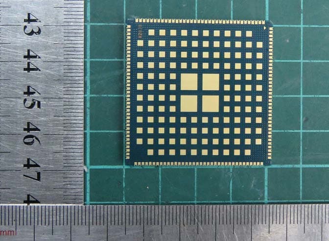
Click to zoom
Application Details
- Equipment Class
- DTS - Digital Transmission System
- Date of Grant
- Jan 03, 2021
- Application Purpose
- Original Equipment
- Date of Application
- Dec 20, 2020
- Equipment Note
- Smart Module
- Frequency Range
- 2412.00000000 - 2462.00000000
- Country
- China
Documents & Files
Document Text
Text extracted from the exhibit documents filed with the FCC. Open a document above to read the original.
Users Manual
SC200R Series Hardware Design Smart Module Series Version: 1.1 Date: 2020-09-09 Status: Released www.quectel.com Smart Module Series SC200R Series Hardware Design SC200R_Series_Hardware_Design 1 / 125 Our aim is to provide customers with timely and comprehensive service. For any assistance, please contact our company headquarters: Quectel Wireless Solutions Co., Ltd. Building 5, Shanghai Business Park Phase III (Area B), No.1016 Tianlin Road, Minhang District, Shanghai 200233, China Tel: +86 21 5108 6236 Email: [email protected] Or our local office. For more information, please visit: http://www.quectel.com/support/sales.htm. For technical support, or to report documentation errors, please visit: http://www.quectel.com/support/technical.htm or email to [email protected]. GENERAL NOTES QUECTEL OFFERS THE INFORMATION AS A SERVICE TO ITS CUSTOMERS. THE INFORMATION PROVIDED IS BASED UPON CUSTOMERS’ REQUIREMENTS. QUECTEL MAKES EVERY EFFORT TO ENSURE THE QUALITY OF THE INFORMATION IT MAKES AVAILABLE. QUECTEL DOES NOT MAKE ANY WARRANTY AS TO THE INFORMATION CONTAINED HEREIN, AND DOES NOT ACCEPT ANY LIABILITY FOR ANY INJURY, LOSS OR DAMAGE OF ANY KIND INCURRED BY USE OF OR RELIANCE UPON THE INFORMATION. ALL INFORMATION SUPPLIED HEREIN IS SUBJECT TO CHANGE WITHOUT PRIOR NOTICE. DISCLAIMER WHILE QUECTEL HAS MADE EFFORTS TO ENSURE THAT THE FUNCTIONS AND FEATURES UNDER DEVELOPMENT ARE FREE FROM ERRORS, IT IS POSSIBLE THAT THESE FUNCTIONS AND FEATURES COULD CONTAIN ERRORS, INACCURACIES AND OMISSIONS. UNLESS OTHERWISE PROVIDED BY VALID AGREEMENT, QUECTEL MAKES NO WARRANTIES OF ANY KIND, IMPLIED OR EXPRESS, WITH RESPECT TO THE USE OF FEATURES AND FUNCTIONS UNDER DEVELOPMENT. TO THE MAXIMUM EXTENT PERMITTED BY LAW, QUECTEL EXCLUDES ALL LIABILITY FOR ANY LOSS OR DAMAGE SUFFERED IN CONNECTION WITH THE USE OF THE FUNCTIONS AND FEATURES UNDER DEVELOPMENT, REGARDLESS OF WHETHER SUCH LOSS OR DAMAGE MAY HAVE BEEN FORESEEABLE. COPYRIGHT THE INFORMATION CONTAINED HERE IS PROPRIETARY TECHNICAL INFORMATION OF QUECTEL WIRELESS SOLUTIONS CO., LTD. TRANSMITTING, REPRODUCING, DISSEMINATING AND EDITING THIS DOCUMENT AS WELL AS USING THE CONTENT WITHOUT PERMISSION ARE FORBIDDEN. OFFENDERS WILL BE HELD LIABLE FOR PAYMENT OF DAMAGES. ALL RIGHTS ARE RESERVED IN THE EVENT OF A PATENT GRANT OR REGISTRATION OF A UTILITY MODEL OR DESIGN. Copyright © Quectel Wireless Solutions Co., Ltd. 2020. All rights reserved. Smart Module Series SC200R Series Hardware Design SC200R_Series_Hardware_Design 2 / 125 About the Document Revision History Version Date Author Description 1.0 2019-12-30 Arsene TONG Initial 1.1 2020-09-09 Jasper LAI/ Jamie SHI 1. Updated SC200R-EM frequency bands (Chapter 2.1/6.1): Added B4 in LTE-FDD Deleted B39 in LTE-TDD Added B4 in WCDMA 2. Added Galileo in supported GNSS (Chapter 2.1/2.2/5/6.3). 3. Added a note for the wakeup of LDO6_1V8 during sleep mode (Chapter 3.3). 4. Updated Wi-Fi output power and added Wi-Fi receiving sensitivity (Chapter 4.1.1). 5. Added BT transmitting and receiving performance (Chapter 4.2.1). 6. Added GNSS performance data (Chapter 5.1). 7. Added current consumption of SC200R-CE/-NA (Chapter 7.4). 8. Added RF output power of SC200R-NA (Chapter 7.5). 9. Added RF receiving sensitivity of SC200R-CE/-NA (Chapter 7.6). 10. Updated the maintenance clearance between the module and other components to at least 5 mm (Chapter 8.2). 11. Updated general description of storage, manufacturing and soldering (Chapter 9.1/9.2). 12. Added package weight of the module (Chapter 9.3). Smart Module Series SC200R Series Hardware Design SC200R_Series_Hardware_Design 3 / 125 Contents About the Document ................................................................................................................................... 2 Contents ....................................................................................................................................................... 3 Table Index ................................................................................................................................................... 6 Figure Index ................................................................................................................................................. 8 1 Introduction ........................................................................................................................................ 10 1.1. Safety Information.................................................................................................................... 12 2 Product Concept ................................................................................................................................ 13 2.1. General Description ................................................................................................................. 13 2.2. Key Features ........................................................................................................................... 16 2.3. Functional Diagram ................................................................................................................. 19 2.4. Evaluation Board ..................................................................................................................... 19 3 Application Interfaces ....................................................................................................................... 20 3.1. General Description ................................................................................................................. 20 3.2. Pin Assignment ........................................................................................................................ 21 3.3. Pin Description ......................................................................................................................... 22 3.4. Power Supply ...................................................................................................................…
Text truncated - open the document above for the full version.
Cover Letter(s)
Quectel Wireless Solutions Co., Ltd Request for Confidentiality Date: _2020/12/14_ Subject: Confidentiality Request for: _____ FCC ID: XMR20SC200RWF __ ____ Pursuant to FCC 47 CRF 0.457(d) and 0.459 and IC RSP-100, Section 10, the applicant requests that a part of the subject FCC application be held confidential. Type of Confidentiality Requested Exhibit Short Term Permanent Block Diagrams Short Term External Photos Short Term Permanent* 1 Internal Photos Short Term Permanent Operation Description/Theory of Operation Short Term Permanent Parts List & Placement/BOM Short Term Permanent Tune-Up Procedure Short Term Permanent Schematics Short Term Test Setup Photos Short Term Permanent* User’s Manual *Note: ______(Insert Explanation as Necessary)______ ______ FCC ID: XMR20SC200RWF ___ __ has spent substantial effort in developing this product and it is one of the first of its kind in industry. Having the subject information easily available to "competition" would negate the advantage they have achieved by developing this product. Not protecting the details of the design will result in financial hardship. Permanent Confidentiality: The applicant requests the exhibits listed above as permanently confidential be permanently withheld from public review due to materials that contain trade secrets and proprietary information not customarily released to the public. Short-Term Confidentiality: The applicant requests the exhibits selected above as short term confidential be withheld from public view for a period of ______ days from the date of the Grant of Equipment Authorization and prior to marketing. This is to avoid premature release of sensitive information prior to marketing or release of the product to the public. Applicant is also aware that they are responsible to notify TCB in the event information regarding the product or the product is made available to the public. TCB will then release the documents listed above for public disclosure pursuant to FCC Public Notice DA 04-1705. NOTE for Industry Canada Applications: The applicant understands that until such time that IC distinguishes between Short Term and Permanent Confidentiality, either type of marked exhibit above will simply be marked Confidential when submitted to IC. Sincerely, By: Jean Hu (Signature/Title 2 ) (Print name)
Cover Letter(s)
Quectel Wireless Solutions Co., Ltd Declaration of the Modular Approval Applicant / Grantee Quectel Wireless Solutions Co., Ltd FCC ID: XMR20SC200RWF Model: Smart Module The single module transmitter has been evaluated then tested meeting the requirements under Part 15C Section 212 as below: Modular approval requirement EUT Condition Comply (a) The radio elements of the modular transmitter must have their own shielding. The physical crystal and tuning capacitors may be located external to the shielded radio elements The radio elements of the modular transmitter have their own shielding. YES (b) The modular transmitter must have buffered modulation/data inputs (if such inputs are provided) to ensure that the module will comply with part 15 requirements under conditions of excessive data rates or over-modulation. The modular has buffered data inputs, it is integrated in chip. Please see schematic.pdf YES (c)The modular transmitter must have its own power supply regulation. All power lines derived from the host device are regulated before energizing other circuits internal to SMART MODULE . Please see schematic.pdf YES (d) The modular transmitter must comply with the antenna and transmission system requirements of Sections 15.203, 15.204(b) and 15.204(c). The antenna must either be permanently attached or employ a “unique” antenna coupler (at all connections between the module and the antenna, including the cable). The “professional installation” provision of Section 15.203 is not applicable to modules but can apply to limited modular approvals under paragraph (b) of this section. Device uses a micro-strip trace on the host’s printed circuit board to an antenna connector on the host circuit board. YES (e)The modular transmitter must be tested in a stand-alone configuration, i.e., the module must not be inside another device during testing for compliance with part 15 requirements. Unless the transmitter module will be battery powered, it must comply with the AC line conducted requirements found in Section 15.207. AC or DC power lines and data input/output lines connected to the module must not contain ferrites, unless they will be marketed with the module (see Section 15.27(a)). The length of these lines shall be the length typical of actual use or, if that length is unknown, at least 10 centimeters to insure that there is no SMART MODULE was tested in a stand‐alone configuration via a PCMCIA extender. Please see spurious set‐up YES Quectel Wireless Solutions Co., Ltd coupling between the case of the module and supporting equipment. Any accessories, peripherals, or support equipment connected to the module during testing shall be unmodified and commercially available (see Section 15.31(i)) must not be in side another device during testing. (f)The modular transmitter must be equipped with either a permanently affixed label or must be capable of electronically displaying its FCC identification number. The label position of SMART MODULE is clearly indicated. If the FCC ID of the module cannot be seen when it is installed, then the host label must include the text: Contains FCC ID: XMR20SC200RWF . Please see the label.pdf YES (g) The modular transmitter must comply with any specific rules or operating requirements that ordinarily apply to a complete transmitter and the manufacturer must provide adequate instructions along with the module to explain any such requirements. A copy of these instructions must be included in the application for equipment authorization requirements, which are based on the intendeduse/configurations. SMART MODULE is compliant with all applicable FCC rules. Detail instructions are given in the User Manual. YES (h)The modular transmitter must comply with any applicable RF exposure requirements in its final configuration. SMART MODULE is approved to comply with the applicable RF exposure requirement, please see the MPE evaluation with 20cm as the distance restriction. YES Dated 2020/12/14 By: Jean Hu Signature Printed Title: Certification Section On behalf of : Quectel Wireless Solutions Co., Ltd Telephone: +86-21-51086236 ext 6511
Cover Letter(s)
Quectel Wireless Solutions Co., Ltd POWER OF ATTORNEY DATE: December 14, 2020 To: Federal Communications Commission, Authorization & Evaluation Division, 7435 Oakland Mills Road, Columbia, MD 21046 We, the undersigned, hereby authorize TA Technology (Shanghai) Co., Ltd. /Jinnan Han on our behalf, to apply to FCC on our equipment for FCC ID: XMR20SC200RWF. Any and all acts carried out by TA Technology (Shanghai) Co., Ltd. / Jinnan Han on our behalf shall have the same effect as acts of our own. Sincerely, Signature: Print name: Jean Hu Company: Quectel Wireless Solutions Co., Ltd
External Photos
EUT Appearance Report No.: R2010A0716 TA Technology (Shanghai) Co., Ltd. Page 1 of 1 This report shall not be reproduced except in full, without the written approval of TA Technology (Shanghai) Co., Ltd. EUT Appearance a: EUT Picture 1: Constituents of EUT
Internal Photos
Internal photo Report No.: R2010A0714 TA Technology (Shanghai) Co., Ltd. Page 1 of 1 This report shall not be reproduced except in full, without the written approval of TA Technology (Shanghai) Co., Ltd. Internal photo
RF Exposure Info
MPE TEST REPORT Applicant Quectel Wireless Solutions Co., Ltd FCC ID XMR20SC200RWF Product Smart Module Brand Quectel Model SC200R-WF Report No. R2010A0716-M1 Issue Date December 17, 2020 TA Technology (Shanghai) Co., Ltd. tested the above equipment in accordance with the requirements in FCC 47 CFR Part 1 1.1310. The test results show that the equipment tested is capable of demonstrating compliance with the requirements as documented in this report. Prepared by: Yu Wang Approved by: Guangchang Fan TA Technology (Shanghai) Co., Ltd. No.145, Jintang Rd, Tangzhen Industry Park, Pudong Shanghai, China TEL: +86-021-50791141/2/3 FAX: +86-021-50791141/2/3-8000 MPE Test Report Report No.: R2010A0716-M1 TA Technology (Shanghai) Co., Ltd. TA-MB-01-013S Page 2 of 10 This report shall not be reproduced except in full, without the written approval of TA Technology (Shanghai) Co., Ltd. Table of Contents 1 Test Laboratory ............................................................................................................................... 3 1.1 Notes of the Test Report ......................................................................................................... 3 1.2. Test facility .............................................................................................................................. 3 1.3 Testing Location ...................................................................................................................... 3 1.4 Laboratory Environment .......................................................................................................... 3 2 Description of Equipment under Test .............................................................................................. 5 3 Maximum conducted output power (measured) and antenna Gain ................................................ 6 4 Test Result ..................................................................................................................................... 7 ANNEX A: The EUT Appearance ......................................................................................................... 10 MPE Test Report Report No.: R2010A0716-M1 TA Technology (Shanghai) Co., Ltd. TA-MB-01-013S Page 3 of 10 This report shall not be reproduced except in full, without the written approval of TA Technology (Shanghai) Co., Ltd. 1 Test Laboratory 1.1 Notes of the Test Report This report shall not be reproduced in full or partial, without the written approval of TA technology (shanghai) co., Ltd.The results documented in this report apply only to the tested sample, under the conditions and modes of operation as described herein .Measurement Uncertainties were not taken into account and are published for informational purposes only. This report is written to support regulatory compliance of the applicable standards stated above. 1.2. Test facility FCC (Designation number: CN1179, Test Firm Registration Number: 446626) TA Technology (Shanghai) Co., Ltd. has been listed on the US Federal Communications Commission list of test facilities recognized to perform electromagnetic emissions measurements. 1.3 Testing Location Company: TA Technology (Shanghai) Co., Ltd. Address: No.145, Jintang Rd, Tangzhen Industry Park, Pudong Shanghai, China City: Shanghai Post code: 201201 Country: P. R. China Contact: Fan Guangchang Telephone: +86-021-50791141/2/3 Fax: +86-021-50791141/2/3-8000 Website: http://www.ta-shanghai.com E-mail: [email protected] 1.4 Laboratory Environment Temperature Min. = 18C, Max. = 25 C MPE Test Report Report No.: R2010A0716-M1 TA Technology (Shanghai) Co., Ltd. TA-MB-01-013S Page 4 of 10 This report shall not be reproduced except in full, without the written approval of TA Technology (Shanghai) Co., Ltd. Relative humidity Min. = 30%, Max. = 70% Ground system resistance < 0.5 Ambient noise is checked and found very low and in compliance with requirement of standards. Reflection of surrounding objects is minimized and in compliance with requirement of standards. MPE Test Report Report No.: R2010A0716-M1 TA Technology (Shanghai) Co., Ltd. TA-MB-01-013S Page 5 of 10 This report shall not be reproduced except in full, without the written approval of TA Technology (Shanghai) Co., Ltd. 2 Description of Equipment under Test Client Information Applicant Quectel Wireless Solutions Co., Ltd Applicant address Building 5, Shanghai Business Park Phase III (Area B), No.1016 Tianlin Road, Minhang District, Shanghai, China 200233 Manufacturer Quectel Wireless Solutions Co., Ltd Manufacturer address Building 5, Shanghai Business Park Phase III (Area B), No.1016 Tianlin Road, Minhang District, Shanghai, China 200233 General Technologies Model SC200R-WF SN E18671975000050 Hardware Version R1.0 Software Version SC200RWFNAR04A02 Date of Testing: November 6, 2020~ November 11, 2020 Note: 1. The EUT is sent from the applicant to TA and the information of the EUT is declared by the applicant. 2. All indications of Pass/Fail in this report are opinions expressed by TA Technology (Shanghai) Co., Ltd. based on interpretations and/or observations of test results. Measurement Uncertainties were not taken into account and are published for informational purposes only. MPE Test Report Report No.: R2010A0716-M1 TA Technology (Shanghai) Co., Ltd. TA-MB-01-013S Page 6 of 10 This report shall not be reproduced except in full, without the written approval of TA Technology (Shanghai) Co., Ltd. 3 Maximum conducted output power (measured) and antenna Gain The numeric gain (G) of the antenna with a gain specified in dB is determined by Numeric gain (G)=10^(antenna gain/10) Band Maximum Conducted Output Power (dBm) Antenna Gain (dBi) Numeric gain (dBm) (mW) WIFI 2.4G 18.50 70.795 0.25 1.059 WIFI 5G 17.50 56.234 1.10 1.288 BT 11.00 12.589 0.25 1.059 BLE 2.00 1.585 0.25 1.059 MPE Test Report Report No.: R2010A0716-M1 TA Technology (Shanghai) Co., Ltd. TA-MB-01-013S Page 7 of 10 This report shall not be repro…
Text truncated - open the document above for the full version.
Contact Information
Applicant
Jean Hu
Test Firm
TA Technology (Shanghai) Co., Ltd.Mr. Zhihui Liu
[email protected]86-21-50791141
Technical Specifications
| # | Rule Parts | Frequency Range | Power Output |
|---|---|---|---|
| 2 | 15C | 2.41 GHz - 2.46 GHz | 52.00 mW |
Other Applications from Quectel Wireless Solutions Company Limited
XMR2026FME160X
Sep 11, 2026Wi-Fi & Bluetooth Module
Equipment Class
DSS - Part 15 Spread Spectrum TransmitterXMR2026FCE860X
Sep 11, 2026Wi-Fi & Bluetooth Module
Equipment Class
NII - Unlicensed National Information Infrastructure TXXMRFCH100XH915
Sep 10, 2026Wi-Fi HaLow Module
Equipment Class
DTS - Digital Transmission SystemXMR2026RG255GNA
Sep 04, 20265G RedCap Sub-6 GHz Module
Equipment Class
CBE - Citizens Band End User DevicesXMR2026KGM100XB
Aug 28, 2026Wireless Module for Amazon Sidewalk
Equipment Class
DTS - Digital Transmission System