XNAWSD01Smart Sleep Dock
Withings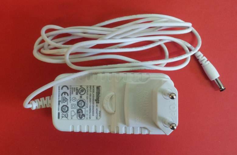
Click to zoom
Application Details
- Equipment Class
- DSS - Part 15 Spread Spectrum Transmitter
- Date of Grant
- Jul 20, 2014
- Application Purpose
- Original Equipment
- Date of Application
- Jul 20, 2014
- Equipment Note
- Smart Sleep Dock
- Frequency Range
- 2402.00000000 - 2480.00000000
- Company
- Withings
- Country
- France
Documents & Files
Document Text
Text extracted from the exhibit documents filed with the FCC. Open a document above to read the original.
Users Manual
1 Quick Start Guide Smart sleep System FR Démarrage rapide | DE Schnellstart ES Inicio rápido | IT Avvio rapido PT Iniciação rápida Aura 2 Thank you for choosing the Withings Aura TM Smart Sleep System FR Merci d’avoir choisi le Withings Aura TM , Smart Sleep System DE Wir bedanken uns für Ihre Wahl des Withings Aura TM , Smart Sleep System ES Gracias por elegir el Withings Aura TM , Smart Sleep System IT Grazie per aver scelto lo Withings Aura TM , Smart Sleep System PT Obrigado por escolher o Withings Aura TM , Smart Sleep System FR Besoin d’aide | DE Brauchen Sie Hilfe ES Necesita ayuda | IT Serve aiuto | PT Necessita ajuda Need help? support.withings.com/aura 3 FR Merci d’avoir choisi le Withings Aura TM , Smart Sleep System DE Wir bedanken uns für Ihre Wahl des Withings Aura TM , Smart Sleep System ES Gracias por elegir el Withings Aura TM , Smart Sleep System IT Grazie per aver scelto lo Withings Aura TM , Smart Sleep System PT Obrigado por escolher o Withings Aura TM , Smart Sleep System FR Contenu de la boîte | DE Inhalt | ES Contenido de la caja | IT Contenuto della confezione | PT Conteúdo da caixa FR Appareil de chevet DE Nachttischgerät ES Dispositivo luminoso y sonoro IT Dispositivo da comodino PT Aparelho de cabeceira FR Capteur sommeil DE Schlafsensor ES Sensor del sueño IT Sensore del sonno PT Captador de sono FR Bloc d’alimentation + adaptateurs locaux DE Netzgerät + lokale Adapter | ES Bloque alimentador de corriente + adaptadores locales IT Alimentatore + adattatori locali | PT Bloco de alimentação + adaptadores locais Box content Bedside deviceSleep sensorPower supply + Local AC plugs 4 Get to know your Withings Aura TM Smart Sleep System FR Apprenez à connaîre votre Withings Aura TM , Smart Sleep System DE Lernen Sie Ihren Withings Aura TM , Smart Sleep System kennen ES Aprenda a utilizar su Withings Aura TM , Smart Sleep System IT Familiarizzate con il vostro Withings Aura TM , Smart Sleep System PT Aprenda a conhecer seu Withings Aura TM , Smart Sleep System 5 Bedside device overview FR Aperçu de votre appareil de chevet | DE Übersicht Ihres Nachttischgeräts | ES Visualización de su dispositivo luminoso y sonoro IT Panoramica del vostro dispositivo da comodino | PT Visão geral do seu aparelho de cabeceira Color LED lighting Clock Display FRONTBACK Touch interfaces Power connector FR Eclairage par led de couleur DE Beleuchtung durch Farb-LEDs ES Iluminación con led de color IT Illuminazione colorata a led PT Iluminação por LED colorido FR Affichage de l’heure DE Anzeige der Uhrzeit ES Visualización de la hora IT Visualizzazione dell’ora PT Apresentação da hora FR Interfaces tactiles DE Berührungsempfindliche Benutzeroberfläche ES Interfaces táctiles IT Touchscreen PT Interfaces táteis USB ports FR Ports USB DE USB-Anschlüsse ES Puerto USB IT Porte USB PT Portas USB FR Connecteur d’alimentation DE Anschluss des Netzsteckers ES Conector de alimentación IT Connettore d’alimentazione PT Conector de alimentação 6 Installation overview FR Aperçu de l’installation | DE Überblick zur Installation | ES Descripción de la instalación | IT Panoramica sull’installazione PT Visão geral da instalação FR Branchez le capteur sur l’un des ports USB de votre appareil de chevet. | DE Schließen Sie den Schlafsensor an einen der USB-Anschlüsse des Nachttischgerätes an. | ES Conecte el sensor a uno de los puertos USB de su dispositivo luminoso y sonoro. | IT Collegate il sensore a una delle porte USB del vostro dispositivo da comodino. | PT Ligue o captador numa das portas USB do seu aparelho de cabeceira. FR Installez le capteur sous votre matelas. DE Installieren Sie den Sensor unter Ihrer Matratze. ES Instale el sensor debajo del colchón. IT Installate il sensore sotto il vostro materasso. PT Instale o captador sob o seu colchão. 1.Place the sensor underneath your mattress FR Placez l’appareil de chevet de votre côté du lit | DE Stellen Sie das Nachttischgerät auf Ihre Seite des Bettes | ES Coloque el dispositivo luminoso y sonoro en su mesilla de noche IT Posizionare il dispositivo da comodino dal vostro lato del letto | PT Coloque o dispositivo de cabeceira do seu lado da cama. 3.Place the bedside device on your side of the bed FR Branchez l’alimentation de votre appareil de chevet. | DE Schließen Sie die Stromversorgung des Nachttischgerätes an. | ES Conecte el suministro de su dispositivo luminoso y sonoro. | IT Collegate l’alimentazione del vostro dispositivo da comodino. | PT Ligue a alimentação do seu aparelho de cabeceira. 4.Connect the power supply of your bedside device. 2.Connect the sleep sensor to a USB port of your bedside device. 7 7.Launch the Health Mate application. FR Lancez l’application Health Mate | DE Starten Sie die Health Mate App | ES Lanzar la aplicación Health Mate IT Avviate l’applicazione Health Mate | PT Lance a aplicação Health Mate. FR Se calibre en dix minutes. S’active en une minute. DE Zehn Minuten Kalibrierung. Eine Minute Aktivierung. ES Se calibra en unos diez minutos. Se activa en un mi- nuto. | IT Si calibra in dieci minuti e si attiva in un minuto. PT Dez minutos para a calibração. Um minuto para a ativação. FR Entrez go.withings.com dans le navigateur de votre smartphone. | DE Schließen Sie die Stromversorgung des Nachttischgerätes an. | ES Entre go.withings.com en el navegador de su smartphone. | IT Digitate go.withings.com nel browser del vostro smartphone. PT Introduza go.withings.com no navegador do seu smartphone. 5.Ten-minute calibration. One-minute activation. 6.Visit go.withings.com in your smartphone’s web browser 10-mn calibration 1-mn activation go.withings.com 8 Main functions of your bedside device FR Interactions principales avec votre appareil de chevet | DE Interaktionen mit dem Nachttischgerät | ES Interacciones principales con su dispositivo luminoso y sonoro | IT Interazioni principali con il vostro dispositivo da comodino | PT Interações principais com o seu aparelho de cabeceira FR Appuyez pour allumer / éteindre la lumièr…
Text truncated - open the document above for the full version.
External Photos
External photos of Withings Aura Smart Sleep Dock FCC ID : XNAWSD01
ID Label/Location Info
15 mm 70 mm DO NOT PRINT BORDERS This device complies with Part 15 of the FCC Rules. Operation is subject to the following two conditions: (1) this device may not cause harmful interference, and (2) this device must accept any interference received, including interference that may cause undesired operation.
ID Label/Location Info
Withings Aura BedsideDevice–Labels location –19/06/2014 Product Label FCC StatementLabel Base of product
ID Label/Location Info
29 mm 37 mm 4 mm 4 mm DO NOT PRINT BORDERS Withings Aura S mart Sleep Dock WSD01 - Designed in France, Made in China FCC ID : XNAWSD01 DC 12V 2.5A IC :11411A-WSD01
Internal Photos
Infernal photos of Withings Aura Smart Sleep Dock FCC ID : XNAWSD01 1. Mother pcb 2. 7-segment PCB 3. Opto PCB 4. Touch PCB
RF Exposure Info
Product name:Smart Sleep Dock Manufacturer:WITHINGS FCC Id:XNAWSD01 Prediction of MPE limit at a given distance Equation from page 18 of OET Bulletin 65, Edition 97-01 where:S = power density P = power input to the antenna G = power gain of the antenna in the direction of interest relative to an isotropic radiator R = distance to the center of radiation of the antenna Transmitter n°1 : wifi Maximum peak output power at the antenna terminal:21.87(dBm) Maximum peak output power at the antenna terminal:153.815464(mW) Antenna gain(typical):3.3(dBi) Maximum antenna gain:2.13796209(numeric) Prediction distance:20(cm) Prediction frequency:2400(MHz) MPE limit for uncontrolled exposure at prediction frequency:1(mW/cm^2) Power density at prediction frequency:0.065423(mW/cm^2) Maximum allowable antenna gain:15.14269855(dBi) Transmitter n°2: BlueTooth - (commun antenna with wifi) Maximum peak output power at the antenna terminal:8.50(dBm) Maximum peak output power at the antenna terminal:7.079457844(mW) Antenna gain(typical):3.3(dBi) Maximum antenna gain:2.13796209(numeric) Prediction distance:20(cm) Prediction frequency:2400(MHz) MPE limit for uncontrolled exposure at prediction frequency:1(mW/cm^2) Power density at prediction frequency:0.003011(mW/cm^2) Maximum allowable antenna gain:28.51269855(dBi) Transmitter n°1 + Transmitter n°2: [Pd(1)/LPd(1)] + [Pd(2)/LPd(2)] =0.06843 <1 2 4R PG S p =
Test Report
TEST REPORT N°128206-657248D Page 2/36 SUMMARY 1. TEST PROGRAM ............................................................................................................................... 3 2. EQUIPMENT DESCRIPTION .............................................................................................................. 4 3. OCCUPIED BANDWIDTH ................................................................................................................... 8 4. -6DB BANDWIDTH ........................................................................................................................... 11 5. MAXIMUM CONDUCTED POWER ................................................................................................... 14 6. POWER SPECTRAL DENSITY ........................................................................................................ 17 7. UNWANTED EMISSIONS INTO NON-RESTRICTED FREQUENCY BANDS AT THE BAND EDGE 20 8. UNWANTED EMISSIONS INTO NON-RESTRICTED FREQUENCY BANDS ................................... 22 9. AC POWER LINE CONDUCTED EMISSIONS ................................................................................. 24 10. UNWANTED EMISSIONS INTO RESTRICTED FREQUENCY BANDS ............................................ 28 11. TEST EQUIPMENT LIST .................................................................................................................. 35 12. UNCERTAINTIES CHART ................................................................................................................ 36 TEST REPORT N°128206-657248D Page 3/36 1. TEST PROGRAM References Standards: - 47 CFR Part 15C - RSS-210 - RSS-Gen - CISPR 16-4-2 - ANSI C63.10 Standard Section Test Description TEST RESULT - Comments RSS-Gen § 4.6.1 Occupied Bandwidth PASS CFR 47 § 15.247 (a) (2) RSS-210 § A8.2(a) -6dB Bandwidth PASS CFR 47 § 15.247 (b) RSS-210 § A8.4(4) Maximum Output Power PASS CFR 47 § 15.247 (e) RSS-210 § A8.2 (b) Power Spectral Density PASS CFR 47 § 15.247 (d) RSS-210 § A8.5 Conducted Spurious Emission at the Band Edge PASS CFR 47 § 15.247 (d) RSS-210 § A8.5 Unwanted Emissions into Non-Restricted Frequency Bands PASS CFR 47 § 15.207 RSS-Gen § 7.2.4 AC Power Line Conducted Emissions PASS CFR 47 § 15.209 (a) CFR 47 § 15.205 (a) CFR 47 § 15.247 (d) RSS-210 § A8.5 Unwanted Emissions into Restricted Frequency Bands PASS RSS-Gen § 4.10 Receiver Radiated emissions PASS (Include in unwanted emission into restricted frequency bands) PASS: EUT complies with standard’s requirement FAIL: EUT does not comply with standard’s requirement NA: Not Applicable NP: Test Not Performed TEST REPORT N°128206-657248D Page 4/36 2. EQUIPMENT DESCRIPTION 2.1. HARDWARE & SOFTWARE IDENTIFICATION Equipment under test (EUT): Photograph of EUT Photograph of EUT TEST REPORT N°128206-657248D Page 5/36 Auxiliary equipment (AE) used for testing: - Personal Computer - USB port to Uart port Photograph of AE Input/output: - Input Power - 3 Usb Software identification: -Software version: firmware_wsd01_20140522-113550_emc_radio Equipment information: - Wifi Version: Bluetooth V4 - Modulation technology: GFSK - Transmit operating mode: Single antenna - Number of transmit chains: 1 - Number of receiver chains: 1 - Type of the equipment: Stand-alone equipment - Type of power source: External power supply - Test source voltage: 120V/60Hz - Antenna type: Integral - Test sequence/test software used: See 2.2. Running Mode - Duty Cycle: Continuous duty - Equipement type: Pre-production model TEST REPORT N°128206-657248D Page 6/36 - Operating frequency range Frequency Band (MHz) 2400MHz to 2483,5MHz - Antenna Characteristics: Antenna Gain (dBi) 3.3 -Channel plan: Channel Frequency (MHz) Channel Frequency (MHz) 0 2402 20 2442 1 2404 21 2444 2 2406 22 2446 3 2408 23 2448 4 2410 24 2450 5 2412 25 2452 6 2414 26 2454 7 2416 27 2456 8 2418 28 2458 9 2420 29 2460 10 2422 30 2462 11 2424 31 2464 12 2426 32 2466 13 2428 33 2468 14 2430 34 2470 15 2432 35 2472 16 2434 36 2474 17 2436 37 2476 18 2438 38 2478 19 2440 39 2480 -Data Rate Data Rate (Mbps) Modulation Type 1 GFSK TEST REPORT N°128206-657248D Page 7/36 2.2. RUNNING MODE The EUT is set in the following modes during tests: - Permanent emission with modulation on a fixed channel in the data rate that produced the highest power - Permanent reception Following commands with the terterm test software are used to set the product: See « WS01_EMI_test_v5.txt » file. 2.3. EQUIPEMENT LABELLING 2.4. EQUIPMENT MODIFICATIONS No equipment modification has been necessary during testing. TEST REPORT N°128206-657248D Page 8/36 3. OCCUPIED BANDWIDTH 3.1. TEST CONDITIONS Test performed by : Arnaud Fayette Date of test : 26/06/2014 Ambient temperature : 24°C Relative humidity : 51% 3.2. TEST SETUP The Equipment Under Test is installed on a table and set in permanent emission with modulation. Measurement is performed with a spectrum analyzer on the EUT conducted access. The product has been tested according to the RSS- GEN § 4.6.1 reference method. Spectrum Analyzer Setting: Center frequency= Cmin or Cnom or Cmax Span= Above the emission spectrum Amplitude= Sufficient to observe the signal amplitude RBW= 1% of span VBW= 3*RBW Sweep= Auto Trace= Max Hold Detector= Peak Occupied Bandwidth 99% activated Photograph for Occupied Bandwidth TEST REPORT N°128206-657248D Page 9/36 3.3. GRAPHICS & RESULTS GFSK Cmin Cnom 0 dBm -10 dBm -20 dBm -30 dBm -40 dBm -50 dBm -60 dBm -70 dBm -80 dBm *Att15 dB * * RBW VBW SWT 100 kHz 300 kHz 2.5ms 1Pk View Ref 9.50 dBm Offs4.50 dB CF2.402 GHzSpan10.0 MHz M1[1]5.01 dBm 2.402000000 GHz Occ Bw1.137724551 MHz T1[1]- 8.07 dBm 2.401441118 GHz T2[1]- 11.24 dBm 2.402578842 GHz M1 T1 T2 Date: 26.JUN.2014 15:08:18 0 dBm -10 dBm -20 dBm -30 dBm -40 dBm -50 dBm -60 dBm -70 dBm -80 dBm *Att15 dB * * RBW VBW SWT 100 kHz 300 kHz 2.5ms 1Pk View Ref 9.50 dBm Offs4.50 dB CF2.442 GHzSpan10.0 MHz M1[1]5.71 dBm 2.441996000 GHz Occ Bw1.177644711 MHz T1[1]- 4.01 dBm 2.4…
Text truncated - open the document above for the full version.
Test Report
TEST REPORT N°128206-657248E Page 2/64 SUMMARY 1. TEST PROGRAM ............................................................................................................................... 3 2. EQUIPMENT DESCRIPTION .............................................................................................................. 4 3. NUMBER OF HOPPING FREQUENCIES ......................................................................................... 10 4. CARRIER FREQUENCY SEPARATION ........................................................................................... 14 5. TIME OF OCCUPANCY .................................................................................................................... 18 6. OCCUPIED BANDWIDTH ................................................................................................................. 23 7. 20DB BANDWIDTH .......................................................................................................................... 27 8. PEAK OUTPUT POWER .................................................................................................................. 31 9. UNWANTED EMISSIONS INTO NON-RESTRICTED FREQUENCY BANDS ................................... 35 10. AC POWER LINE CONDUCTED EMISSIONS.................................................................................. 45 11. UNWANTED EMISSIONS INTO RESTRICTED FREQUENCY BANDS ............................................ 50 12. UNCERTAINTIES CHART ................................................................................................................ 64 TEST REPORT N°128206-657248E Page 3/64 1. TEST PROGRAM References Standards: -47 CFR Part 15C -RSS-210 -RSS-Gen -ANSI C63.10 Radio requirement: Standard Section Test Description TEST RESULT - Comments CFR 47 § 15.247(a)(1) RSS-210 A8.4(2) Number of Hopping Frequencies PASS FAIL NA NP (Limited Program) CFR 47 § 15.247(a)(1) RSS-210 A8.1(b) Carrier Frequency Separation PASS FAIL NA NP (Limited Program CFR 47 § 15.247(a)(1) RSS-210 A8.1(a) Time of Occupancy PASS FAIL NA NP (Limited Program RSS-Gen § 4.6.1 Occupied Bandwidth PASS FAIL NA NP (Limited Program CFR 47 § 15.247 (a) (1) RSS-210 § A8.1(a) 20dB Bandwidth PASS FAIL NA NP (Limited Program CFR 47 § 15.247 (b)(1) RSS-210 § A8.1(b) Peak Output Power PASS FAIL NA NP (Limited Program CFR 47 § 15.247 (d) RSS-210 § A8.5 Unwanted Emissions into Non-Restricted Frequency Bands PASS FAIL NA NP (Limited Program CFR 47 § 15.207 RSS-Gen § 7.2.4 AC Power Line Conducted Emissions PASS FAIL NA NP (Limited Program CFR 47 § 15.209 (a) CFR 47 § 15.205 (a) CFR 47 § 15.247 (d) RSS-210 § A8.5 Unwanted Emissions into Restricted Frequency Bands PASS FAIL NA NP (Limited Program RSS-Gen § 4.10 Receiver Radiated emissions PASS (Include in Unwanted Emission into Restricted Bands) FAIL NA NP (Limited Program) This table is a summary of test report, see conclusion of each clause of this test report for detail. The product Withings AuraTM WSD01, SN: 0024E4182A06 is Compliant according to FCC 15.247, RSS-210, RSS-Gen standards. PASS: EUT complies with standard’s requirement FAIL: EUT does not comply with standard’s requirement NA: Not Applicable NP: Not Performed TEST REPORT N°128206-657248E Page 4/64 2. EQUIPMENT DESCRIPTION 2.1. GENERAL DESCRIPTION The Withings Aura TM Bedside Device is a connected and active product designed to both monitor and improve sleep quality. It ‘connects’ to the outside world through Wi-Fi, USB, Bluetooth and Bluetooth Low Energy. It is ‘active’ as it includes multi-color LED lighting and audio diffusion capabilities. Withings Aura discreetly records environment data (light, sound, temperature) and gathers sleep quality data from external sensors connected to it through the USB ports (NB: the USB-connected sensors are outside of the WSD01/Withings Aura Bedside Device perimeter). This recorded data allows to get a complete understanding of sleep patterns. The Withings Aura TM Bedside Device then uses light and sound programs to positively impact wake-up and fall-asleep experiences, which are both instrumental in improving sleep quality and overall well-being. It also offers additional options to create personal ambiances for relaxation and powernaps through light and sound programs. 2.2. HARDWARE & SOFTWARE IDENTIFICATION Equipment under test (EUT): Photograph of EUT TEST REPORT N°128206-657248E Page 5/64 Photograph of EUT Auxiliary equipment (AE) used for testing: - Personal Computer - USB port to Uart port Photograph of AE TEST REPORT N°128206-657248E Page 6/64 Input/output: - Input Power - 3 Usb Software identification: -Software version: firmware_wsd01_20140522-113550_emc_radio Equipment information: - Bluetooth Version: 1.2 2.0 2.1+EDR 3.0+HS - Modulation technology: FHSS modulation - EIRP: See 3.3. Result - Transmit operating mode: Multiples antenna without beam forming Multiples antenna with beam forming Single antenna - Number of transmit chains: 1 - Number of receiver chains: 1 - Antenna type: Integral External - Antenna Gain: 3.3dBi - Beamforming gain: Yes No - Type of the equipment: Stand-alone equipment Plug-in radio device Combined equipment - Test source voltage: Vnom: 120V/60Hz Vdc - Type of power source: Battery (Alkaline/Lithium-Ion/Lead acid/Other) Internal power supply External power supply Car Charger - Test sequence/test software used: See 2.2. Running Mode - Ad-hoc mode: Yes No - Minimum number of hopping frequency: 20 - Maximum number of hopping frequency: 79 - Duty Cycle: Continuous duty Intermittent duty Continuous operation - Equipement type: Representative production model Pre-production model TEST REPORT N°128206-657248E Page 7/64 - Operating frequency range Frequency Band (MHz) 2400MHz to 2483,5MHz 5150MHz to 5350MHz 5470MHz to 5725MHz MHz to MHz -Channel plan: Channel Frequency (MHz) Channel Frequency (MHz) Channel Frequency (MHz) 0 2402 27 2429 54 2456 1 2403 28 2430 55 2457 2 2404 29 2431 56 2458 3 2405 30 2432 57 2…
Text truncated - open the document above for the full version.
Test Report
TEST REPORT N°128206-657248F Page 2/57 SUMMARY 1. TEST PROGRAM ............................................................................................................................... 3 2. EQUIPMENT DESCRIPTION .............................................................................................................. 4 3. OCCUPIED BANDWIDTH ................................................................................................................... 9 4. -6DB BANDWIDTH ........................................................................................................................... 12 5. MAXIMUM CONDUCTED POWER ................................................................................................... 15 6. POWER SPECTRAL DENSITY ........................................................................................................ 22 7. UNWANTED EMISSIONS INTO NON-RESTRICTED FREQUENCY BANDS AT THE BAND EDGE 29 8. UNWANTED EMISSIONS INTO NON-RESTRICTED FREQUENCY BANDS ................................... 33 9. AC POWER LINE CONDUCTED EMISSIONS ................................................................................. 37 10. UNWANTED EMISSIONS INTO RESTRICTED FREQUENCY BANDS ............................................ 41 11. TEST EQUIPMENT LIST .................................................................................................................. 56 12. UNCERTAINTIES CHART ................................................................................................................ 57 TEST REPORT N°128206-657248F Page 3/57 1. TEST PROGRAM References Standards: - 47 CFR Part 15C - RSS-210 - RSS-Gen - CISPR 16-4-2 - ANSI C63.10 Standard Section Test Description TEST RESULT - Comments RSS-Gen § 4.6.1 Occupied Bandwidth PASS CFR 47 § 15.247 (a) (2) RSS-210 § A8.2(a) -6dB Bandwidth PASS CFR 47 § 15.247 (b) RSS-210 § A8.4(4) Maximum Output Power PASS CFR 47 § 15.247 (e) RSS-210 § A8.2 (b) Power Spectral Density PASS CFR 47 § 15.247 (d) RSS-210 § A8.5 Conducted Spurious Emission at the Band Edge PASS CFR 47 § 15.247 (d) RSS-210 § A8.5 Unwanted Emissions into Non-Restricted Frequency Bands PASS CFR 47 § 15.207 RSS-Gen § 7.2.4 AC Power Line Conducted Emissions PASS CFR 47 § 15.209 (a) CFR 47 § 15.205 (a) CFR 47 § 15.247 (d) RSS-210 § A8.5 Unwanted Emissions into Restricted Frequency Bands PASS RSS-Gen § 4.10 Receiver Radiated emissions PASS include in unwanted emission into restricted frequency bands PASS: EUT complies with standard’s requirement FAIL: EUT does not comply with standard’s requirement NA: Not Applicable NP: Test Not Performed TEST REPORT N°128206-657248F Page 4/57 2. EQUIPMENT DESCRIPTION 2.1. HARDWARE & SOFTWARE IDENTIFICATION Equipment under test (EUT): Photograph of EUT TEST REPORT N°128206-657248F Page 5/57 Auxiliary equipment (AE) used for testing: - Personal Computer - Wifi Access Point - USB port to Uart port Photograph of AE Input/output: - Input Power - 3 Usb Software identification: -Software version: firmware_wsd01_20140522-113550_emc_radio Equipment information: - Wifi Version: 802.11b, 802.11g, 802.11n HT20 - Modulation technology: OFDM and DSSS modulation - Number of simultaneous channels: 1 - Transmit operating mode: Single antenna - Number of transmit chains: 1 - Number of receiver chains: 1 - Beamforming gain: No - Type of the equipment: Stand-alone equipment - Type of power source: External power supply - Antenna type: Integral - Test sequence/test software used: See 2.2. Running Mode - Duty Cycle: Continuous duty - Equipement type: Pre-production model TEST REPORT N°128206-657248F Page 6/57 - Operating frequency range Frequency Band (MHz) 2400MHz to 2483,5MHz - Antenna Characteristics: Antenna Gain (dBi) 3.3 -Channel plan 802.11b, 802.11g & 802.11n HT20: Channel Frequency (MHz) Cmin: 1 2412 2 2417 3 2422 4 2427 5 2432 Cnom: 6 2437 7 2442 8 2447 9 2452 10 2457 Cmax: 11 2462 -Channel plan 802.11n HT40: Channel Frequency (MHz) Cmin: 3 2422 4 2427 5 2432 Cnom: 6 2437 7 2442 8 2447 Cmax: 9 2452 TEST REPORT N°128206-657248F Page 7/57 -Data Rate: 802.11b Data Rate (Mbps) Modulation Type 1 DBPSK 2 DQPSK 5,5 DQPSK 11 CCK 802.11g Data Rate (Mbps) Modulation Type 6 BPSK 9 BPSK 12 QPSK 18 QPSK 24 16-QAM 36 16-QAM 48 64-QAM 54 64-QAM 802.11n HT20 MCS index Spatial streams Modulation Type Data rate (Mbit/s) GI=800ns GI=400ns 0 1 BPSK 6.50 7.20 1 1 QPSK 13.00 14.40 2 1 QPSK 19.50 21.70 3 1 16-QAM 26.00 28.90 4 1 16-QAM 39.00 43.30 5 1 64-QAM 52.00 57.80 6 1 64-QAM 58.50 65.00 7 1 64-QAM 65.00 72.20 TEST REPORT N°128206-657248F Page 8/57 2.2. RUNNING MODE The EUT is set in the following modes during tests: - Permanent emission with modulation on a fixed channel in the data rate that produced the highest power (802.11b: 11Mbps, 802.11g: 6Mbps, 802.11n HT20: 6.5Mbps) - Permanent reception Following commands with the specific test software “TERATERM” are used to set the product: See « WS01_EMI_test_v5.txt » file. 2.3. EQUIPEMENT LABELLING 2.4. EQUIPMENT MODIFICATIONS No equipment modification has been necessary during testing. TEST REPORT N°128206-657248F Page 9/57 3. OCCUPIED BANDWIDTH 3.1. TEST CONDITIONS Test performed by : Arnaud Fayette Date of test : 25/06/2014 Ambient temperature : 22°C Relative humidity : 43% 3.2. TEST SETUP The Equipment Under Test is installed on a table and set in permanent emission with modulation. Measurement is performed with a spectrum analyzer on the EUT conducted access. The product has been tested according to the RSS- GEN § 4.6.1 reference method. Spectrum Analyzer Setting: Center frequency= Cmin or Cnom or Cmax Span= Above the emission spectrum Amplitude= Sufficient to observe the signal amplitude RBW= 1% of span VBW= 3*RBW Sweep= Auto Trace= Max Hold Detector= Peak Occupied Bandwidth 99% activated Photograph for Occupied Bandwidth TEST REPORT N°128206-657248F Page 10/57 3.3. GRAPHICS & RESULTS 802.11b Cmin Cnom Cmax 10 dBm 0 dBm -10 dBm -20 dBm -30 dBm -40 dBm -50 dBm -60 dBm -70 d…
Text truncated - open the document above for the full version.
Test Setup Photos
Test setup photos FCC Id: XNAWSD01 Test setup for power line conducted emissions Test setup for power line conducted emissions Test setup for power line conducted emissions Test setup for radiated field strength Test setup for radiated field strength Test setup for radio conducted tests
Contact Information
Applicant
Xavier Debreuil(Product Director)
Test Firm
LCIE Sud-EstJacques Lorquin
Technical Specifications
| # | Rule Parts | Frequency Range | Power Output |
|---|---|---|---|
| 1 | 15C | 2.40 GHz - 2.48 GHz | 7.00 mW |
Other Applications from Withings
XNAWBS15
May 15, 2026Withings BodyScan 2
Equipment Class
DTS - Digital Transmission SystemXNASCT02
Jul 03, 2024SCT02
Equipment Class
DTS - Digital Transmission SystemXNAWBS14
Jan 25, 2024WITHINGS BODY PRO 2
Equipment Class
DTS - Digital Transmission System
XNAHWA10
Jul 31, 2023HWA10
Equipment Class
DTS - Digital Transmission System
XNAWBS08
Apr 03, 2023Withings Body Scan
Equipment Class
DTS - Digital Transmission System