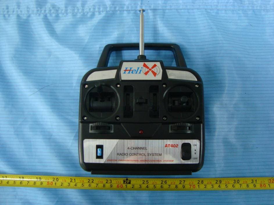
XNS-ATTXRemote Control Transmitter
Taizhou Best Team Technology Limited
Click to zoom
Application Details
- Equipment Class
- DXX - Part 15 Low Power Communication Device Transmitter
- Date of Grant
- Jul 08, 2010
- Application Purpose
- Original Equipment
- Date of Application
- Jul 08, 2010
- Equipment Note
- Remote Control Transmitter
- Frequency Range
- 2418.00000000 - 2467.60000000
- Country
- China
Documents & Files
Document Text
Text extracted from the exhibit documents filed with the FCC. Open a document above to read the original.
Users Manual
INSTRUCTION MANUAL Digital Proportional Radio Control System Taizhou Best Team Technology Limited www.rcmodel.net SAFETY NOTES Please read through the instructions carefully before using this radio. Pay much attention to all precautions and warnings to ensure the safest operation. WARNINGS Do not fly in the rain or at night. Water can permanently damage many of the components in the radio system, possibly causing loss of the control and a crash. Only fly at designated R/C flying fields. Fly at safe distances away from other people, objects in the air, buildings, electrical lines, or any other object which could possible impede safe flying. Failure to do so could cause a crash and possibly bodily harm and physical damage to other property. Always test the radio system before use. Make sure the operation of each channel in the radio is in the proper direction. If a channel does not accurately respond according to the transmitter input, do not fly the model. Check for and correct improperly functioning equipment before use. Failure to ensure proper radio operation before flight could result in a crash. During flight preparations, be certain to place the transmitter on its back when on the ground, to prevent it from accidentally falling over and inadvertently moving the throttle stick to high speed. Do not allow fuel or oil on the plastic parts. Some plastics may melt when exposed to such material. Before turning on the transmitter, adjust the throttle stick to minimum speed position. After stopping the engine turn “OFF”, the transmitter power switch, then turn “Off” the transmitter power switch. Failure to follow this order could cause the engine to go to full throttle and cause an injury. Do not make adjustments to the radio system while the engine is running unless absolutely necessary. Failure to do so could cause the engine to accidentally go to high speed and cause an injury. The transmitter is designed for use with 8 dry cell (Non-rechargeable) AA size alkaline batteries or rechargeable NiMh cells (available separately). If using rechargeable batteries, please follow the charging instructions supplied by the manufacturer of the batteries. Never attempt to charge non-chargeable alkaline dry cell batteries as there is a risk of fire, damage and personal injury. Always full charge the transmitter and receiver battery before each flight. Failure to do so could cause an inadvertent power failure and a crash. Use the charger supplied with this supplied with this radio. If using another charger, do not overcharge the battery, as it could cause burns, fire, injury or other equipment damage. Do not short circuit the battery terminals, as arcing, overheating or fire could result. Do not leave the radio system, batteries, model helicopter or other equipment within the reach of children. Do not overheat or throw the batteries into a fire. Leaking electrolyte from the battery could cause injury, such as burns or blindness. In case of emergency, immediately flush you eyes, skin or cloths with plenty of water and see a doctor. Recycle the battery when no longer in usable condition. Store the radio with all NiMh batteries in the discharged state and be certain to full charge the batteries just prior to use. Do not store the radio system in extreme heat or cold, in direct sunlight, in high humidity, in high vibration environments or in dusty areas. NAME AND HANDLING OF EACH PART Servo reversing switches (Option Function) Switches that reverse the direction of operation of the servos The lower position is the normal side and the upper position is the reverse side. Channel display Operating direction display AIL. : Aileron(CH1) REV. : Reverse side ELE. : Elevator(CH2) NOR. : Normal THR. : throttle(CH3) RUD. :Rudder(CH4) Power switch in the upper position, the power is turned on . LED Power on Hook Aileron trim lever Rudder trim lever Throttle (model 1) Elevator (model 2) /Aileron stick Elevator (model 1) Throttle (model 2) /rudder stick Carrying bar 2.4G Antenna Throttle trim lever (model 1) Elevator trim lever (model 2) Elevator trim lever (model 1) Throttle trim lever (model 2) Battery Box Cover Use when replacing the battery Battery Box Charging Jack Charging jack when the transmitter was converted to NiMh battery system. Aileron Control (CH1): When the aileron stick is mover to the right, the right aileron is raised and the left aileron is raised and the left aileron is lowered and the helicopter banks to the right. When the aileron stick is moved to the left, the ailerons move in the opposite direction and the helicopter banks left. To level the helicopter, the aileron stick must be move in the opposite direction and back to center. Elevator Control (CH2): When the elevator stick is pulled back, the tail elevator is raised and the tail of the helicopter is forced down, thus causing the model to climb (Up Operation), When the elevator stick is pushed forward, the elevator is lowered, the tail of the model is forced up, thus causing the model to descend (Down Operation). Throttle Control (CH3): When the throttle stick is pulled back, the engine throttle lever arm moves to the slow (Low Speed) side. When the throttle stick is pushed forward, the throttle lever arm moves to the High (High Speed) side. Rudder Control (CH4): When the rudder stick is moved to the right, the rudder moves to the right and nose points to the right, thus causing the model to turn right. When the rudder stick is moved to the left, the rudder moves to the leftˈ and the nose points to the left, thus causing the model to turn left. SERVO INSTRLLATION All servos should be mounted as shown in the model’s instructions. Use the rubber grommets, screws and brass eyelets supplied when mounting your servos. Do not over-tighten the mounding screws. The servos should be able to move slightly to compensate for engine vibration. For each servo, use a servo horn long enough to accommodate the entire range of movement for that particular cont…
Text truncated - open the document above for the full version.
Block Diagram
CPU Power Low voltage Detection and Indication Control Value 2.4G Module OSC: 26MHz Simulator Port
Cover Letter(s)
TAIZHOU BEST TEAM TECHNOLOGY LIMITED 21.6.2010 To: SIEMIC, INC. 2206 Ringwood Avenue, San Jose, CA 95131 USA Dear Sir/Madam, Re: Project and Product Certification Representative Authorization Letter We, Taizhou Best Team Technology Limited hereby authorize SIEMIC, INC. to act as a Certification Body for certifying for the following project(s): Product name: Remote Control Transmitter Model:AT401, AT402 We affirm that between SIEMIC and Taizhou Best Team Technology Limited, any difference in understanding, including test plan, measurement methods, applicable standards and relevant procedures and processes have been resolved prior to commencement of testing activities. Sincerely, Alan Chen / Vice Chief Manager Taizhou Best Team Technology Limited Shenlong Industrial Park, Jiangyan City, Jiangsu 225500, China
ID Label/Location Info
FCC Certification Label Sample FCC ID: XNS-ATTX This device complies with Part 15 of the FCC Rules. Operation is subject to the following two conditions: (1) This device may not cause harmful interference, and (2) This device must accept any interference received, including interference that may cause undesired operation.
ID Label/Location Info
FCC Certification label location Sample Label location
Internal Photos
Antenna
Operational Description
Operation Description The 2.4G four/five/six-channel radio control transmitter is based on DSSS 2.4G Hz frequency band. It transmits control values to wireless receivers. The four-channels radio receivers will use the four firstcomer control values and the five-channels radio receives will use the five firstcomer control values and six-channels receives will use the all control values. Just loading cell, open the power switch, the transmitter automatically search idle channels and occupys the first channel has been found. Each transmitter has a exclusive ID, with the same IDCODE receiver to complete confirmation. Antenna is formed by a copper trace on the PCB. Common grounding on PCB is not connected to real external ground. Power supply is DC 6V by four “AA” batteries.
Schematics
ABCD DCBA R15 R12 Vbatt+ C15 LowBatt_det C23 C24 C22 +3.3V Vbatt+ 12 J2 CH1 C13 123456789101112 J1 +3.3V+3.3V+3.3V+3.3V CH1CH2CH3CH4 R6 ad_CH1 CH2 C14 R7 ad_CH2 CH3 C16 R8 ad_CH3 CH4 C17 R9 ad_CH4 R3 +3.3V Q4 R11 LED C21 S1 S7 SW1 SW2_mix Tx_data LED AD_CH4AD_CH3AD_CH2AD_CH1LowBatt_det SW1 SW2_mix S5 DC1 D1 D2 12 LED1 PS_DATA R20 sw_ch4sw_ch3 R21 S6 R19 +3.3V S4 S3 SW_ch4SW_ch3 S2 SW_ch2 sw_ch2sw_ch1 +3.3V Q7 R22 R23 +3.3V Tx_data 12 CN3 12345678 JP1 +3.3VMOSISCLKMISOGDO2GNDPA/GDO0CS_RF +3.3V +3.3V MOSISCLKMISO GDO2 PA/GDO0CS_RF SW_ch1 GND 1 Vout 2 Vin 3 U2 C20 C25 C11 C10 C12 C17 C13 C18 +3.0V R4 GDO0GDO2CS_RFSCLKMOSIMISO SCLK 1 SO(GDO1) 2 DVDD 4 DCOUPL 5 XOSC_Q1 8 AVDD 9 XOSC_Q2 10 GDO2 3 CSn 7 RF_P 12 RF_N 13 AVDD 11 AVDD 14 RBIAS 17 DGUARD 18 SI 20 GND(PAD) 0 GDO0 6 AVDD 15 GND 16 GND 19 U3 +3.0V +3.0V C16 ANTENNA 1 P1 C20 C21 1 2 L2 C19 12 L1 C22 +3.0V +3.0V +3.0V C28 C29 1 3 Y1 26M 123456789 10 11121314151617181920 C?
Test Report
Page 1 of 46 FCC ID: XNX-ATTX ACCURATE TECHNOLOGY CO. LTD REPORT NO. ATE20101382 FCC CERTIFICATION On Behalf of TAIZHOU BEST TEAM TECHNOLOGY LIMITED Remote Control Transmitter Model No.: AT401, AT402 FCC ID: XNS-ATTX Prepared for : TAIZHOU BEST TEAM TECHNOLOGY LIMITED Address : SHENLONG INDUSTRIAL PARK, JIANGYAN CITY JIANGSU 225500, CHINA Prepared by : ACCURATE TECHNOLOGY CO. LTD Address : F1, Bldg. A, Changyuan New Material Port, Keyuan Rd. Science & Industry Park, Nanshan, Shenzhen, Guangdong P.R. China Tel: (0755) 26503290 Fax: (0755) 26503396 Report Number : ATE20101382 Date of Test : July 5, 2010 Date of Report : July 7, 2010 Page 2 of 46 FCC ID: XNX-ATTX ACCURATE TECHNOLOGY CO. LTD REPORT NO. ATE20101382 TABLE OF CONTENTS Description Page Test Report Certification 1.GENERAL INFORMATION ..........................................................................................................4 1.1.Description of Device (EUT)....................................................................................................................4 1.2.Description of Test Facility ......................................................................................................................4 1.3.Measurement Uncertainty.........................................................................................................................5 2.MEASURING DEVICE AND TEST EQUIPMENT ..................................................................... 6 3.SUMMARY OF TEST RESULTS................................................................................................... 7 4.FUNDAMENTAL AND HARMONICS RADIATED EMISSION FOR SECTION 15.249(A) 8 4.1.Block Diagram of Test Setup....................................................................................................................8 4.2.The Emission Limit ..................................................................................................................................9 4.3.Configuration of EUT on Measurement ...................................................................................................9 4.4.Operating Condition of EUT ....................................................................................................................9 4.5.Test Procedure ........................................................................................................................................10 4.6.The Field Strength of Radiation Emission Measurement Results ..........................................................11 5.SPURIOUS RADIATED EMISSION FOR SECTION 15.249(D) ............................................. 14 5.1.Block Diagram of Test Setup..................................................................................................................14 5.2.The Emission Limit For Section 15.249(d) ............................................................................................15 5.3.EUT Configuration on Measurement .....................................................................................................15 5.4.Operating Condition of EUT ..................................................................................................................15 5.5.Test Procedure ........................................................................................................................................16 5.6.The Emission Measurement Result ........................................................................................................17 6.BAND EDGES ................................................................................................................................. 20 6.1.The Requirement ....................................................................................................................................20 6.2.EUT Configuration on Measurement .....................................................................................................20 6.3.Operating Condition of EUT ..................................................................................................................20 6.4.Test Procedure ........................................................................................................................................20 6.5.The Measurement Result ........................................................................................................................21 7.ANTENNA REQUIREMENT........................................................................................................ 23 7.1.The Requirement ....................................................................................................................................23 7.2.Antenna Construction .............................................................................................................................23 APPENDIX I ( TEST CURVES) (22 pages) Page 3 of 46 FCC ID: XNX-ATTX ACCURATE TECHNOLOGY CO. LTD REPORT NO. ATE20101382 Test Report Certification Applicant : TAIZHOU BEST TEAM TECHNOLOGY LIMITED Manufacturer : TAIZHOU BEST TEAM TECHNOLOGY LIMITED EUT Description : Remote Control Transmitter (A) MODEL NO.: AT401, AT402 (B) SERIAL NO.: N/A (C) POWER SUPPLY: 6V DC (“AA” batteries 4h) Measurement Procedure Used: FCC Rules and Regulations Part 15 Subpart C Section 15.249 ANSI C63.4: 2003 The device described above is tested by ACCURATE TECHNOLOGY CO. LTD to determine the maximum emission levels emanating from the device. The maximum emission levels are compared to the FCC Part 15 Subpart C Section15.249 limits. The measurement results are contained in this test report and ACCURATE TECHNOLOGY CO. LTD is assumed full responsibility for the accuracy and completeness of these measurements. Also, this report shows that the Equipment Under Test (EUT) is to be technically compliant with the FCC requirements. This report applies to above tested sample only. This report shall not be reproduced in part without written approval of ACCURATE…
Text truncated - open the document above for the full version.
Test Setup Photos
Radiated emissions test < 1GHz Radiated emissions test > 1GHz
Contact Information
Applicant
Alan Chen
Test Firm
Accurate Technology Co., Ltd.Sean Liu
Technical Specifications
| # | Rule Parts | Frequency Range | Power Output |
|---|---|---|---|
| 1 | 15C | 2.42 GHz - 2.47 GHz | - |
Other Applications from Taizhou Best Team Technology Limited
XNS052720010
Mar 09, 2011Radio Control Transmitter
Equipment Class
TNB - Licensed Non-Broadcast Station Transmitter