XRQWTP100ELITE TRUE POWER METER
Efergy Technologies Limited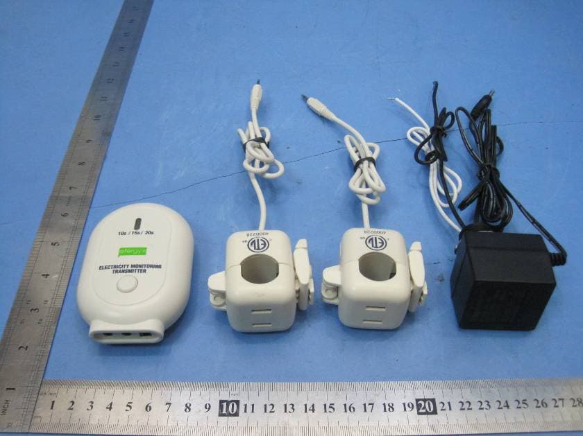
Click to zoom
Application Details
- Equipment Class
- DSC - Part 15 Security/Remote Control Transmitter
- Date of Grant
- Mar 06, 2012
- Application Purpose
- Original Equipment
- Date of Application
- Mar 06, 2012
- Equipment Note
- ELITE TRUE POWER METER
- Frequency Range
- 433.50000000 - 433.50000000
- Company
- Efergy Technologies Limited
- Country
- China
Documents & Files
Document Text
Text extracted from the exhibit documents filed with the FCC. Open a document above to read the original.
Users Manual
*All values shown in this manual are only examples. Actual figures will vary depending on your consumption. CT SensorTransmitter 10 / 15 / 20s ELECTRICITY MONITORING TRANSMITTER 2. Plug the CT sensors’ jacks into the transmitter 1. Open and place one CT sensor around each mains cable Do not touch below this level 1. Pull the clasp to open the CT sensor 2. Place the CT sensor around the cable 3. Push the clasp to close securely Wireless energy monitor link button Hold for 2 seconds history backward forward mode/set INSTANT MODE MONITOR SETUP 1516 Push the mode/set button to change information being displayed from kW to cost (displayed in $). Cost and Emission Per Day or Hour Energy Now The lower part of the screen shows Shows the instant power in kW. the estimated cost and carbon emissions per day or hour. Push the History button to access daily, weekly and monthly stored data. Use the backward and forward arrow buttons to scroll between dates and compare consumption data. Press the mode/set button to change the information display from kWh to costs and CO 2 emissions. Historical consumption information for days, weeks and months in kWh, $ and KgCO 2 Average information for days, weeks and months in kWh, $ and KgCO 2 HISTORY MODE FA S 1817 If I remove the batteries will I lose the information on the display? The display has an internal memory, so if you need to change or remove the batteries the information stored on it will not be lost. How do I reset the display (clear the stored data and start again)? Pr ess and hold the mode/set and History buttons simultaneously for 2 seconds. How far does the device transmit? The transmitter work up to ar ound 230ft/ 40m within the home. The 433MHz range is well suited for in-home use. This can cover 3 floors and is also ideal for buildings where electricity meters are situated outside. I have dashes (- - - -) showing on the display. What does this mean? Move the display closer to the transmitter and pr ess the link button. If the dashes remain on the display this would indicate that the transmitter and receiver ar e not communicating. Please contact efergy customer services to help solve the problem, at [email protected] The backlight appears to work sometimes and then not others. Is it broken? No. The backlight is on a timer to save battery life. The display should work at darker periods during the day when any buttons ar e pr essed. The LED backlight will be activated fr om 18:00 hours - 6:00 hours. TECHNICAL INFORMATION Model Name Model Number Fr equency Transmission Time Transmission Range Working voltage range Measuring Current Carbon Ratio Elite true power meter Elite-TPM-NA 1.0 433.5MHz 10, 15 or 20 seconds 230ft - 328ft/ 40m - 70m 110V - 600V 50mA-200A (MAX) 0.50kg.CO 2 / kWh ELECTRICITY SYSTEMVOLT SETTING AT 1.120V, 3 Wire, Single Phase (TYPICAL RESIDENTIAL SERVICE IN US & CANADA) 120 2.240V, 3 Wire, Single Phase 240 3.120/ 208V, 3 Wire, 2 Phases of a 3 Phase 120/208V Three wires phase 1 live, phase 2 live, Grid 120V is live to neutral and 208 is phase 120 to phase. Assume unbalanced load. 2 CT Sensors 4.120/ 208V, 4 Wire, 3 Phases, Balanced Load Three phase live, phase 2 live - Neutral, where 120V is phase to neutral and 208V 208 is phase to phase. 1 CT Sensor 5.120/ 208V, 4 Wire, 3 Phases, Unbalanced Load The display does not recognize unbalanced loads inthis configuration. The degree 120 of accuracy will be relative to the amount of unbalanced current. 3 CT Sensors 6.208V, 3 Phase Delta Balanced Load 208 7.277/ 480V, 4 Wire, 3 Phases, Balanced Load Three phase live + neutral, where 277V is phase to neutral and 480V is phase to 480 phase. 1CT Sensor 8.277/ 480V, 4 Wire, 3 Phases, Unbalanced Load Three phase live + neutral, where 277V is phase to neutral and 480V is phase to phase. The display does not recognize unbalanced loads in this configuration. 277 The degree of accuracy will be relative to the amount of unbalanced current. 3 CT Sensors 9.230/ 400V, 4 Wire, 3 Phases, Balanced Load Three phase live + neutral, where 230V is phase to neutral and 400V is phase to 400 phase. 1CT Sensor 10.347/ 575V, 3 Phase, Balanced Load. 1CT Sensor 580 11.347/ 575V, 3 Phase, Unbalanced Load. The display does not recognize unbalanced loads in this configuration. The degree 350 of accuracy will be relative to the amount of unbalanced current. 3 CT Sensors
Block Diagram
1 2 3 4 56 ABCD 6 5 4 3 2 1 D CBA Titl e Nu mber Rev i sio n Size B Dat e: 1 6-Nov -20 1 1 Sheet o f File: d :\my d o cu ment s\ desk to p \W TP1 00 . Dd b Drawn By: T1 AC 1 1 0V 78L05 7225 VPIAPIBP ADE7 7 5 8 5V 7 7 5 8 - DOUT7758-SCLK7758-DIN7758-CS HT 4 6 R2 3 2 2.5V ISL12058 2.5V 24C02 2.5V2.5V 7302-DATA 7302-CS 7302 SCLSDA 12058-CLK 12058-SCL 12058-SDA 13.25MHz
External Photos
2.1 Product View 2.2 EUT - Appearance View
ID Label/Location Info
Page 32 of 32 Efergy Technologies Limited FCC ID: XRQWTP100 The results shown in this test report refer only to the sample(s) tested , This Test report cannot be reproduced, except in full, without prior written permission of the Company. WALTEK SERVICES Reference No.: WT11126777-D-E-F 13 FCC Label This device complies with Part 15 of the FCC Rules. Operation is subject to the following two conditions: (1) this device may not cause interference, and (2) this device must accept any interference, including interference that may cause undesired operation of the device. The Label must not be a stick-on paper. The Label on these products must be permanently affixed to the product and readily visible at the time of purchase and must last the expected lifetime of the equipment not be readily detachable. Proposed Label Location on EUT EUT Bottom View/proposed FCC Label Location FCC ID: XRQWTP100 This device complies with Part 15 of the FCC Rules. Operation is subject to the following two conditions: (1) this device may not cause harmful interference, and (2) this device must accept any interference received, including interference that may cause undesired operation.
ID Label/Location Info
FCC ID Label Sample for Model: Elite-TPM-NA 1.0 FCC ID: XRQWTP100 This device complies with Part 15 of the FCC Rules. Operation is subject to the following two conditions: (1) this device may not cause harmful interference, and (2) this device must accept any interference received, including interference that may cause undesired operation.
Internal Photos
2.1 EUT - Open View 2.2 EUT - PCB View 2.3 CT Sensor - Appearance View 2.4 CT Sensor - Open View 2.5 CT Sensor - Internal View 2.6 Adapter - Appearance View 2.7 Adapter - Open View 2.8 Adapter - Internal View
Operational Description
Circuit Description The power meter takes samples of the voltage via the AC/DC adapter, takes the samples of the current via the CT sensor, the sample data of the voltage and current is sent to IC ADE7758(utilizing 10MHz OSC) for transforming, calculating and checking, after that, the data is sent to MCU HT46R232 (utilizing 8MHz OSC) for further processing. The MCU gets the exctly time via External timer IC 12058(utilizing 32.768kHz OSC), and access the data via EEPROM IC 24C02. After processed by the MCU, the data is sent to the RF IC A7302(utilizing 13.25MHz OSC), the RF IC transmits the data to the space by 433.5MHz carrier signal with FSK modulation. The transmitting interval may be 10s/15s/20s, and the power meter could change on the three kind of intervals automatically. The power is powered by a AC/DC adapter with 120VAC input.
Schematics
1 2 3 4 56 ABCD 6 5 4 3 2 1 D CBA Titl e Number Revision Size B Date: 16-Nov-2011 Sheet of File: d :\my d o cu ment s\ desk to p \W TP1 00 . Dd b Drawn By: T1 1 R115R C1 220UF/16V Vin 1 GND 2 Vo ut 3 U1780L5 C2104 C3220UF C4104 Vin 1 GND 2 Vo ut 3 U2HT7225 C510UF C6104 D14001 ACC 5V APCF 1 DGND 2 DVDD 3 AVDD 4 1AP 5 IAN 6 IB P 7 IB N 8 IC P 9 IC N 10 AGND 11 REF 12 VN 13 VCP 14 VBP 15 VAP 16 VARCF 17 IR Q 18 CLKIN 19 CLKOUT 20 CS 21 DIN 22 SCLK 23 DOUT 24 U6ADE7758 Y310M C23 104 C2 4 10UF C2520PC2620P R2 22K R24270 C18333 R261K R291K C22333 C2 0333 L3 IAPIAN 5V VP VCPVNIANIB PIB NIAP R2 32K R31270 C29333 R271K R321K C31333 C3 0333 L4 IB PIB N R968K R251K C19333 R281K C21333VN VP ACC 7758-DOUT7758-SCLK7758-DIN7758-CS Y48M C2720PC2820P PB5/AN5 1 PB4/AN4 2 PA3/PDF 3 PA2 4 PA1 5 PA0 6 PB3/AN3 7 PB2/AN2 8 PB1/AN1 9 PB0/AN0 10 VSS 11 PC0/TX 12 PC1/RX 13 PC2 14 PB6/ AN6 28 PB7/ AN7 27 PA4 26 PA5/INT 25 PA6/SDA 24 PA7/SCL 23 OSC2 22 OSC1 21 VDD 20 /RES 19 PD1/PWM1 18 PD0/PWM0 17 PC4 16 PC3 15 U7HT46 RU2 32 R30100K Q19014 R33100K C32104 5V 7 75 8 -DOUD7758-SCLK7728-DIN12058-CLK 12058-SCL12058-SDA 512 SDA512 SCL 7758-CS A0 1 A1 2 A2 3 VSS 4 SDA 5 SCL 6 WP 7 VCC 8 U424C02 R1010K R1110K VCC2 512 SCL512 SDA OSCI 1 OSCO 2 /INT 3 GND 4 SDA 5 SCL 6 CLKOUT 7 VDD 8 U5ISL12058 Y232.768K C1015P C1115P VCC C35104 R1210K R1310K R1410K 12058-CLK12058-SCL12058-SDA CHECK Net Lab el 12 7 LINK7103-CS7103-DATASENSOR-LXSENSOR-MINSENSOR-MIC LED1LED2 Y113.25M C915P L156NH C1627P E1 C15104 C1 3104 L218NH 2 C173.6P C87.5P MODE 1 TX-DATA 2 CE 3 VDD-D 4 VDD-A 5 PA-OUT 6 GND 7 XI 8 FSK-SW 9 SPIS 10 U3A7 30 2 R715R R6100 C1 4100P C7100P R210KR310K R420K R520K 2.5V 2.5V 7302-DATA7302-CS R1710K R1810K R1910K R2 010K CHECKSENSOR-LXSENSOR-MINSENSOR-MIC S1 S2 S3 R2110K SW1 LINK 5V R1 5470 D3LED D2LED R1 61K LED2 LED1 2.5V AC 1 1 0V C33 104 C34104 S4
Test Report
Page: 1 of 34 FCC TEST REPORT The results shown in this test report refer only to the sample(s) tested , This Test report cannot be reproduced, except in full, without prior written permission of the Company. WALTEK SERVICES Reference No.: WT11126777-D-E-F FCC ID : XRQWTP100 Applicant : Efergy Technologies Limited Address : 105, Bld 18, Bishui Haoyuan, Nanhuan Rd, Binjiang, Hangzhou, Zhejiang China Equipment Under Test (EUT) : Product Name : Elite true power meter Model No. : Elite-TPM-NA 1.0 Standards : FCC CFR47 Part 15 Section 15.231:2010 Date of Test : December 3 ~ December 16, 2011 Date of Issue : December 30, 2011 Test Engineer : Hunk yan / Engineer Reviewed By : Philo zhong / Manager Test Result : PASS Prepared By: Waltek Services (Shenzhen) Co., Ltd. 1/F, Fukangtai Building, West Baima Rd., Songgang Street, Baoan District, Shenzhen 518105, China Tel :+86-755-27553488 Fax:+86-755-27553868 The sample detailed above has been tested to the requirements of Council Directives ANSI C63.4:2003. The test results have been reviewed against the Directives above and found to meet their essential requirements. Page 2 of 34 Efergy Technologies Limited FCC ID: XRQWTP100 The results shown in this test report refer only to the sample(s) tested , This Test report cannot be reproduced, except in full, without prior written permission of the Company. WALTEK SERVICES Reference No.: WT11126777-D-E-F 2 Content Page 1 COVER PAGE ........................................................................................................................................................ 1 2 CONTENT............................................................................................................................................................... 2 3 TEST SUMMARY .................................................................................................................................................. 4 4 GENERAL INFORMATION ................................................................................................................................ 5 4.1 CLIENT INFORMATION........................................................................................................................................... 5 4.2 GENERAL DESCRIPTION OF E.U.T. ........................................................................................................................ 5 4.3 DETAILS OF E.U.T................................................................................................................................................. 5 4.4 DESCRIPTION OF SUPPORT UNITS.......................................................................................................................... 5 4.5 STANDARDS APPLICABLE FOR TESTING................................................................................................................ 5 4.6 TEST FACILITY...................................................................................................................................................... 6 4.7 TEST LOCATION.................................................................................................................................................... 6 5 EQUIPMENT USED DURING TEST .................................................................................................................. 7 6 CONDUCTED EMISSION TEST......................................................................................................................... 8 6.1 TEST EQUIPMENT.................................................................................................................................................. 8 6.2 TEST PROCEDURE.................................................................................................................................................. 8 6.3 CONDUCTED TEST SETUP...................................................................................................................................... 8 6.4 EUT OPERATING CONDITION................................................................................................................................9 6.5 CONDUCTED EMISSION LIMITS.............................................................................................................................. 9 6.6 CONDUCTED EMISSION TEST DATA.................................................................................................................... 10 7 RADIATION EMISSION TEST ......................................................................................................................... 12 7.1 TEST EQUIPMENT................................................................................................................................................ 12 7.2 MEASUREMENT UNCERTAINTY........................................................................................................................... 12 7.3 TEST PROCEDURE................................................................................................................................................ 12 7.4 RADIATED TEST SETUP....................................................................................................................................... 13 7.5 SPECTRUM ANALYZER SETUP............................................................................................................................. 14 7.6 CORRECTED AMPLITUDE & MARGIN CALCULATION........................................................................................... 15 7.7 SUMMARY OF TEST RESULTS.............................................................................................................................. 15 7.8 EUT OPERATING CONDITION.............................................................................................................................. 15 7.9 RADIATED EMISSIONS LIMIT............................................................................................…
Text truncated - open the document above for the full version.
Test Setup Photos
2.1 Radiated Emissions Test Setup View Below 1GHz Above 1GHz 2.2 Conducted Emissions Test Setup View
Contact Information
Applicant
Munro Don(Director)
Test Firm
Waltek Services(Shenzhen) Co., Ltd.Philo zhong
Technical Specifications
| # | Rule Parts | Frequency Range | Power Output |
|---|---|---|---|
| 1 | 15.231 | 433.5 MHz - 433.5 MHz | - |
Other Applications from Efergy Technologies Limited
XRQEMTX
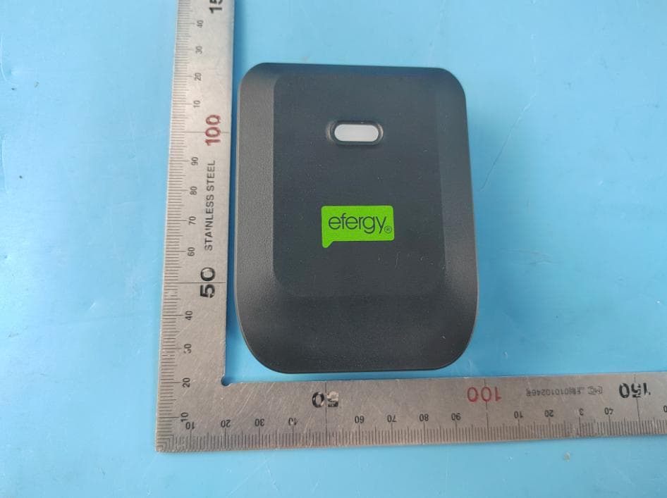
Jun 28, 2023Black Transmitter
Equipment Class
DSC - Part 15 Security/Remote Control Transmitter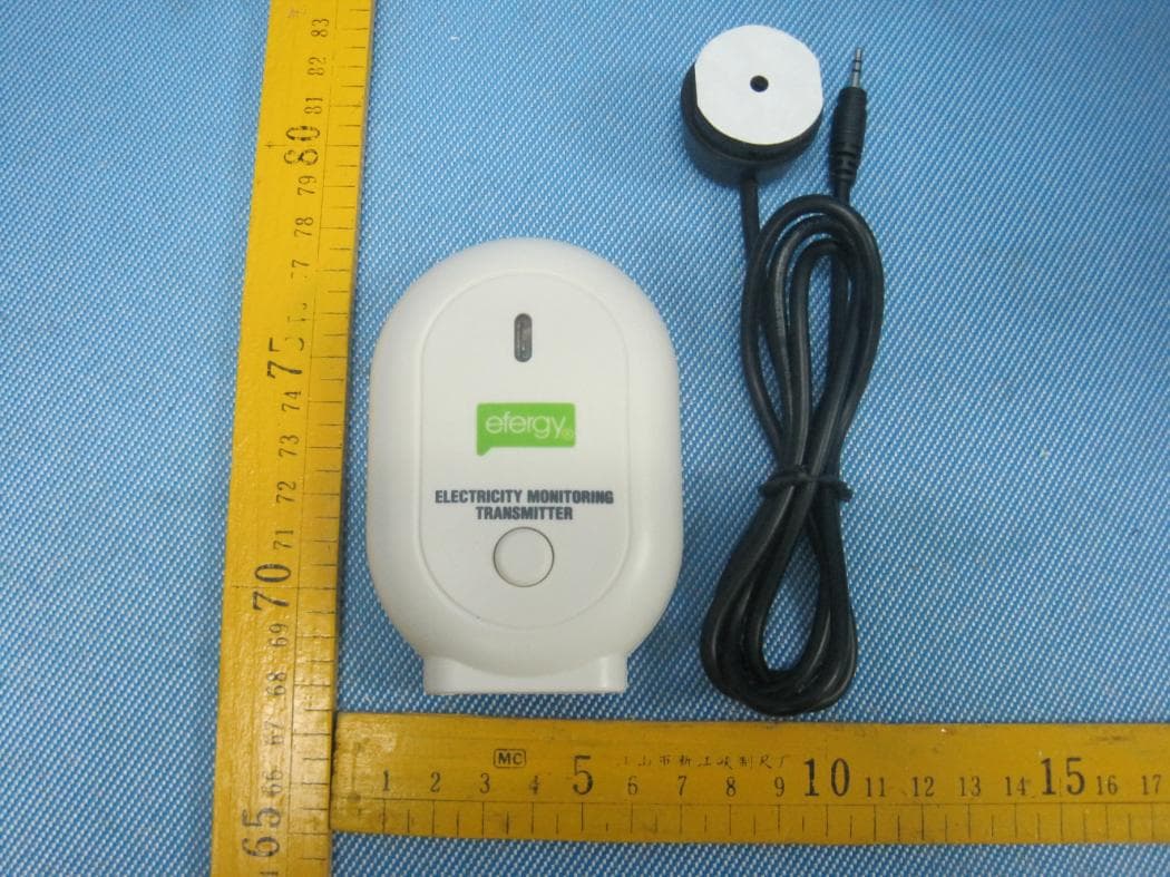
XRQELITEIR
Oct 11, 2012IR-TX
Equipment Class
DSC - Part 15 Security/Remote Control Transmitter