XTNTP9100ID CARD PRINTER
TIT ENG Co.,Ltd.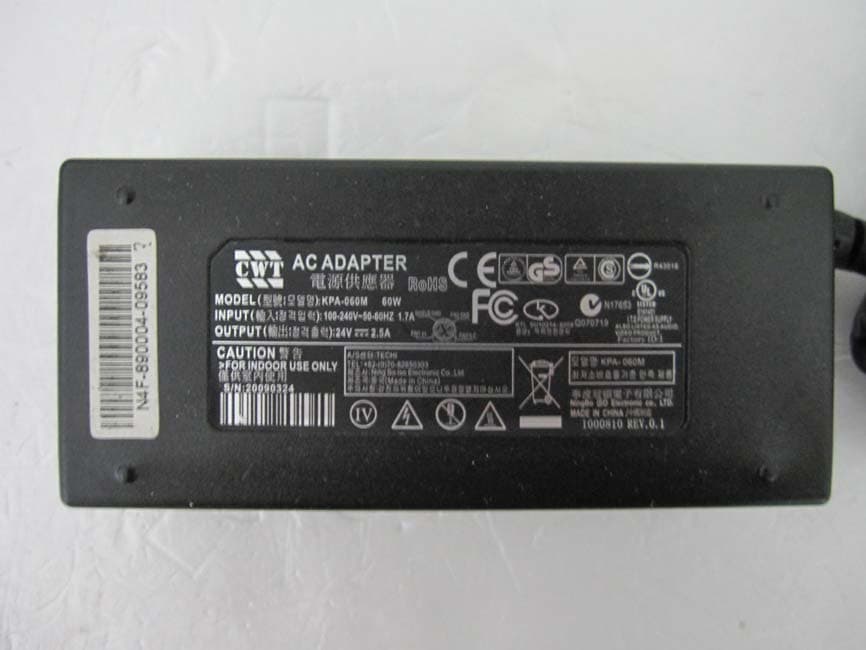
Click to zoom
Application Details
- Equipment Class
- DXX - Part 15 Low Power Communication Device Transmitter
- Date of Grant
- Nov 30, 2010
- Application Purpose
- Original Equipment
- Date of Application
- Nov 28, 2010
- Equipment Note
- ID CARD PRINTER
- Frequency Range
- 13.56000000 - 13.56000000
- Company
- TIT ENG Co.,Ltd.
- Country
- South Korea
Documents & Files
Document Text
Text extracted from the exhibit documents filed with the FCC. Open a document above to read the original.
Users Manual
Cover User’s Manual Page 2 Contents Contents ...................................................... 02 Caution ...................................................... 04 1. Getting Started 1.1 Introduction 1.2 Contents in Package 1.3 Product Features 1.4 Loading Ribbon Cartridge 1.5 Loading Cleaning Rollers 1.6 Card Feeding Hopper 1.7 Card Output Stacker 1.8 Power Device, Power cable, Communication Cable 2. Software Installation 2.1 Installing FTD2xx Direct USB Driver 2.2 Installing Microsoft Windows Application Software / Driver 2.3 Removing FTD2xx Direct USB Driver 2.4 Removing TP-9100 Application Software / Driver 2.5 Printing with TP-9100 on Microsoft Windows Application Software 2.6 Printer Settings in Microsoft Windows 2.7 Printer Driver Settings 3. Printer Operating 3.1 Getting Started 3.2 Description on Features 3.3 Designing Card Page 3 Contents 3.4 Tools 3.5 Configuration 3.6 Data Synchronizing 3.7 Card Printing 4. Instructions on Maintenance 4.1 Maintenance of Product 4.2 How to Replace Ribbon Cartridge 4.3 How to Clean the Printer 4.4 How to Replace TPH(Thermal Print Head) and Consumables 4.5 Trouble-shooting 4.6 Technical Specifications Page 4 User should read caution information and keep in mind before using. Different icons remind important information as to safety. TIT Eng is not responsible for physical harm to body or physical damage to the product occurred by user’s careless use. Danger : Warns user of risk of losing life or being seriously injured. Warning : Warns user of risk of being seriously or slightly injured, or damage to product. Caution : Warns you of slight damage to body. Note : Indicates information that supplements detailed information. Page 5 Danger : Warns user of risk of losing life or being seriously injured. POWER Do not use damaged power cord, plug or socket. Do not pull plug with power cord line. Do not touch power plug with wet bare hand. Do not bend power cord or put heavy things on the power cord. Unplug during thunder and lightning or storage INSTALLATION Do not put the printer in wet, dirty place. Do not put lightings on the printer. Put the printer away from heat source. Unplug while moving the printer Put the printer away from flammable source. CLEANING Clean the wet and dirty plug. Unplug the printer before cleaning. Do not use water or chemical cleanser. MISCELLANEOUS Do not put water bowel, medicine, metal on the printer. In case of abnormal situation in the printer, unplug the printer immediately and contact your dealer. Make sure that you use adequate power adaptor. Page 6 Caution : Warns you of slight damage to body. INSTALLATION Do not put the printer on unstable place. Avoid direct sunlight that may cause trouble. CLEANING Do not disassemble cover or protection parts. When you put hand inside the printer, do not operate it Make sure that you perform cleaning and maintaining according to the instructions. MISCELLANEOUS Do not disassemble, repair, modify. Do not put heavy things on the printer. Page 7 1. Getting Started 1.1 Introduction This card printer enables user to create cards easily and shortly in accordance with the card specifications you wish to get. You can get high quality color image with the card printer of dye sublimation printing. In order to meet customers demand, it provides options such as M/S, IC(Contact), RF(Contactless) encoding as well as bar code, diagram, picture printing. It is useful for creating membership card, bonus card and identification card on PET, PVC card. 1.2 Contents in Package TP-9000 , TP-9100 CLEANING ROLLER, POWER ADAPTOR, POWER CABLE, USB PRINTER CABLE, SOFTWARE CD, USER MANUAL, STACKER(not applicable for TP-9000), CLEANING CARD * Please make sure that printer and all the accessories are in good order. If any items are missing, please contact your dealer. Page 8 1.3 Product Features TP-9000 (Manual, Single Printing) Front Rear Side Features Description No Features Description 1 LED Display LED shows the status of printer 2 LCD Display LCD panel displays the status of printer 3 Card Eject Button for ejecting card from the printer 4 Ribbon Load Button for replacing or repositioning ribbon cartridge 5 Mobile Connector Socket for mobile chip 6 Power Button Power on and off (Option) 7 Card Output Stacker Stacker for released output cards 8 Printer Lid Open for replacing ribbons and cleaning rollers 9 Flipper Used for Dual sided printing (Option) 10 USB Socket Used for memory stick or USB connecting 11 USB Communication Port Used for connecting PC and printer with USB cable 12 RS232C Communication Port Used for connecting PC and printer with RS232C 13 Power Socket Used for supplying power 14 External RF Recognize RF Card Page 9 TP-9100 (Auto Continuous Printing) Front Rear Side Features Description No Features Description 1 LED Display LED shows the status of printer 2 LCD Display LCD panel displays the status of printer 3 Card Eject Button for discharging card inside the printer 4 Ribbon Load Button for replacing or relocating ribbon cartridge 5 Mobile Connector Socket for mobile chip 6 Power Button Power on and off (Option) 7 Card Output Stacker Stacker for released output cards 8 Printer Lid Open for replacing ribbons and cleaning rollers 9 Flipper Used for Dual sided printing (Option) 10 USB Socket Used for memory stick or USB connecting 11 USB Communication Port Used for connecting PC and printer with USB cable 12 RS232C Communication Port Used for connecting PC and printer with RS232C 13 Power Socket Used for supplying power 14 External RF Recognize RF Card * Even though we have three different models of TP series, since there is no big difference in operation, user’s manual has been designed for TP-9100 Dual Sided as main reference. Page 10 TP-9100 (Dual Sided, Auto Continuous Printing) Front Rear Side Features Description No Features Description 1 LED Display LED shows the status of printer 2 LCD Display LCD panel displays the status of printer 3 Card…
Text truncated - open the document above for the full version.
Cover Letter(s)
TIT ENG CO., Ltd. 7 Floor, Shin-do B/D. 10, Garak-dong, Songpa-Gu, Seoul, Korea, 138-160 Date: September 17, 2010 Compliance Certification Services Certification Division 47173 Benicia Street Fremont, CA 94538, USA RE: Request of Confidentiality for FCCID: XTNTP9100 To Whom It may Concern: Pursuant to Sections 0.457 and 0.459 of the Commission`s Rules(CFR 47), and Section 552 (b) (4) of the Freedom of Information Act, TIT ENG CO., Ltd. hereby requests confidentiality and treatment of certain information accompanying this application. The materials contain trade secrets and proprietary information not customarily released to the public. The public disclosure of these matters might be harmful to the Applicant and provide unjustified benefits to its competitors. We are also hereby request Short-Term Confidentiality for 180 days after the grant as outlined in Public Notice DA 04-1705. This provision will give TIT ENG CO., Ltd. temporary confidentiality of commercially sensitive information prior to product release. The requested permanent and Short-Term Confidential exhibits are listed as follows: PERMANENT & SHORT-TERM CONFIDENTIAL LIST Exhibit Description File name PERMANENT 1 Block Diagram Block Diagram_XTNTP9100.pdf 2 Operational Description Operational Description_XTNTP9100.pdf 3 Schematics Schematic_XTNTP9100.pdf 4 Part Lists Part List_XTNTP9100.pdf SHORT-TERM 5 External Photos Ext Photo_XTNTP9100.pdf 6 Internal Photos Int Photo_XTNTP9100.pdf 7 Test-Setup Photos Test Photo_XTNTP9100.pdf 8 Users Manual User Manual_XTNTP9100.pdf Note: The pictures on the label location do not require any long term or short term confidentiality. The Applicant understands that pursuant to Rule 0.457, disclosure of this application and all accompanying documentations, where applicable, will not be public before the date of the Grant for this application. Sincerely, Sang-Joong Lee Senior Engineer
Cover Letter(s)
TIT ENG CO., Ltd. 7 Floor, Shin-do B/D. 10, Garak-dong, Songpa-Gu, Seoul, Korea, 138-160 Date: September 17, 2010 Compliance Certification Services Certification Division 47173 Benicia Street Fremont, CA 94538, USA LETTER OF AUTHORIZATION We, the undersigned, hereby authorize Harvey Sung of Digital EMC Co., Ltd. to act on our behalf in all manners relating to application for equipment authorization for FCC ID: XTNTP9100 including signing of all documents relating to these matters. Any and all acts carried out by Harvey Sung of Digital EMC Co., Ltd. on our behalf shall have the same affect as acts of our own. This authorization is valid until further written notice from TIT ENG CO., Ltd. Sincerely, Sang-Joong Lee Senior Engineer
External Photos
FCCID: XTNTP9100 Copyright Ⓒ 2010, Digital EMC Co., Ltd. View 1 FCCID: XTNTP9100 Copyright Ⓒ 2010, Digital EMC Co., Ltd. View 2 FCCID: XTNTP9100 Copyright Ⓒ 2010, Digital EMC Co., Ltd. View 3 FCCID: XTNTP9100 Copyright Ⓒ 2010, Digital EMC Co., Ltd. View 4
ID Label/Location Info
FCC ID: XTNTP9100 Copyright Ⓒ 2010, Digital EMC Co., Ltd. FCC ID SAMPLE LABEL & LOCATION LABELLING REQUIREMENTS PER §2.925 The Label shown shall be permanently affixed at a conspicuous location on the device and be readily visible to the user at the time of purchase
Internal Photos
FCCID: XTNTP9100 Copyright Ⓒ 2010, Digital EMC Co., Ltd. Page1 / 29 View 1 FCCID: XTNTP9100 Copyright Ⓒ 2010, Digital EMC Co., Ltd. Page2 / 29 View 2 FCCID: XTNTP9100 Copyright Ⓒ 2010, Digital EMC Co., Ltd. Page3 / 29 View 3 FCCID: XTNTP9100 Copyright Ⓒ 2010, Digital EMC Co., Ltd. Page4 / 29 View 4 FCCID: XTNTP9100 Copyright Ⓒ 2010, Digital EMC Co., Ltd. Page5 / 29 View 5 FCCID: XTNTP9100 Copyright Ⓒ 2010, Digital EMC Co., Ltd. Page6 / 29 View 6 FCCID: XTNTP9100 Copyright Ⓒ 2010, Digital EMC Co., Ltd. Page7 / 29 View 7 FCCID: XTNTP9100 Copyright Ⓒ 2010, Digital EMC Co., Ltd. Page8 / 29 View 8 FCCID: XTNTP9100 Copyright Ⓒ 2010, Digital EMC Co., Ltd. Page9 / 29 View 9 FCCID: XTNTP9100 Copyright Ⓒ 2010, Digital EMC Co., Ltd. Page10 / 29 View 10 FCCID: XTNTP9100 Copyright Ⓒ 2010, Digital EMC Co., Ltd. Page11 / 29 View 11 FCCID: XTNTP9100 Copyright Ⓒ 2010, Digital EMC Co., Ltd. Page12 / 29 View 12 FCCID: XTNTP9100 Copyright Ⓒ 2010, Digital EMC Co., Ltd. Page13 / 29 View 13 FCCID: XTNTP9100 Copyright Ⓒ 2010, Digital EMC Co., Ltd. Page14 / 29 View 14 FCCID: XTNTP9100 Copyright Ⓒ 2010, Digital EMC Co., Ltd. Page15 / 29 View 15 FCCID: XTNTP9100 Copyright Ⓒ 2010, Digital EMC Co., Ltd. Page16 / 29 View 16 FCCID: XTNTP9100 Copyright Ⓒ 2010, Digital EMC Co., Ltd. Page17 / 29 View 17 FCCID: XTNTP9100 Copyright Ⓒ 2010, Digital EMC Co., Ltd. Page18 / 29 View 18 FCCID: XTNTP9100 Copyright Ⓒ 2010, Digital EMC Co., Ltd. Page19 / 29 View 19 FCCID: XTNTP9100 Copyright Ⓒ 2010, Digital EMC Co., Ltd. Page20 / 29 View 20 FCCID: XTNTP9100 Copyright Ⓒ 2010, Digital EMC Co., Ltd. Page21 / 29 View 21 FCCID: XTNTP9100 Copyright Ⓒ 2010, Digital EMC Co., Ltd. Page22 / 29 View 22 FCCID: XTNTP9100 Copyright Ⓒ 2010, Digital EMC Co., Ltd. Page23 / 29 View 23 FCCID: XTNTP9100 Copyright Ⓒ 2010, Digital EMC Co., Ltd. Page24 / 29 View 24 FCCID: XTNTP9100 Copyright Ⓒ 2010, Digital EMC Co., Ltd. Page25 / 29 View 25 FCCID: XTNTP9100 Copyright Ⓒ 2010, Digital EMC Co., Ltd. Page26 / 29 View 26 - Top Antenna FCCID: XTNTP9100 Copyright Ⓒ 2010, Digital EMC Co., Ltd. Page27 / 29 View 27 - Internal Antenna FCCID: XTNTP9100 Copyright Ⓒ 2010, Digital EMC Co., Ltd. Page28 / 29 View 28 - Ribbon Antenna FCCID: XTNTP9100 Copyright Ⓒ 2010, Digital EMC Co., Ltd. Page29 / 29 View 29
Test Report
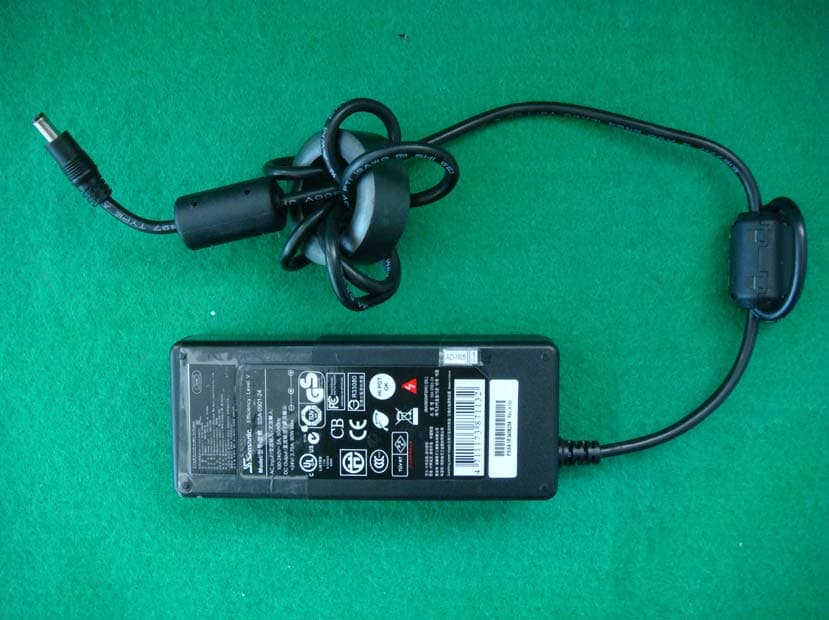
1006-00266 DRTFCC1010-0236 TRF-RF-203(01)100722 Page 2 / 29 Copyright ○ C 2010, Digital EMC Co., Ltd. CONTENTS 1. Equipment information ...................................................................... 3 1.1 Equipment description ..................................................................... 3 1.2 Ancillary equipment .......................................................................... 3 2. Information about test items ............................................................. 4 2.1 Test mode ......................................................................................... 4 2.2 Auxiliary equipment .......................................................................... 4 2.3 Tested frequency .............................................................................. 4 2.4 Tested environment .......................................................................... 4 2.5 EMI Suppression Device(s)/Modifications ....................................... 4 3. Test Report .......................................................................................... 5 3.1 Summary of tests ............................................................................. 5 3.2 Transmitter requirements ................................................................. 6 3.2.1 20dB Bandwidth Measurement (§2.1049) ................................... 6 3.2.2 In-Band Radiated Spurious Emission (§15.225(a), (b), (c)) ........ 9 3.2.3 Radiated Spurious Emission Measurements, Out-of-Band (§15.225(d) / §15.205 and 209) ............................ 12 3.2.4 Frequency Stability (§15.225(e)) ............................................... 16 3.2.5 AC Line Conducted Emissions (§15.207/EN 55022) ................. 20 APPENDIX ............................................................................................. 27 1006-00266 DRTFCC1010-0236 TRF-RF-203(01)100722 Page 3 / 29 Copyright ○ C 2010, Digital EMC Co., Ltd. 1. Equipment information 1.1 Equipment description FCC Equipment Class Low Power Communications Device Transmitter(DXX) Equipment type ID Card Printer Equipment model name TP-9100 Equipment add model name Javelin J230i Equipment serial no. Identical prototype Frequency band 13.56MHz Modulation type ASK Channel 1 Supplied tag type 14443A, 14443B, Mifare Power AC 120V Antenna type PCB Loop antenna Note 1 Note 1: This device has 3 PCB Loop antennas.(Top, Internal, Ribbon) But this device does not support a simultaneous transmission mode. 1.2 Ancillary equipment Equipment Model No. Serial No. Manufacturer Note AC Adapter KPA-060M 20090324 Ning Bo Iso Electronic Co., Ltd. Output DC 24V RFID Tag 14443A N/A SuremRFID Co., Ltd. - RFID Tag 14443B N/A SuremRFID Co., Ltd. - RFID Tag Mifare N/A SuremRFID Co., Ltd. - R F I D Ta g Ta g ( M i f a r e ) N/A Cobis Co., Ltd. - 1006-00266 DRTFCC1010-0236 TRF-RF-203(01)100722 Page 4 / 29 Copyright ○ C 2010, Digital EMC Co., Ltd. 2. Information about test items 2.1 Test mode Test Case 1 Top Antenna Test Case 2 Internal Antenna Test Case 3 Ribbon Antenna 2.2 Auxiliary equipment Equipment Model No. Serial No. Manufacturer Note - - - - - - - - - - 2.3 Tested frequency TX Frequency (MHz) RX Frequency (MHz) Lowest Channel 13.56 13.56 Middle Channel - - Highest Channel - - 2.4 Tested environment Temperature : 24 ~ 25 °C Relative humidity content : 35 ~ 58 % R.H. Details of power supply :AC 120 V (Output: DC 24V) 2.5 EMI Suppression Device(s)/Modifications EMI suppression device(s) added and/or modifications made during testing → The manufacturer carried out modifications to the EUT in order to meet the requirements Of the standard applied. Below ferrites fitted to adapter cable.(refer to external photo.) - 85R142806-00A - 85R142806-00A 1006-00266 DRTFCC1010-0236 TRF-RF-203(01)100722 Page 5 / 29 Copyright ○ C 2010, Digital EMC Co., Ltd. 3. Test Report 3.1 Summary of tests FCC Part Section(s) Parameter Limit Test Condition Status Note 1 I. Test Items 2.1049 20 dB Bandwidth N/A Radiated C Note. 2 15.225 (a) In-Band Emissions 15.848㎶/m @ 30m 15.553 – 13.567 MHz C Note. 2 15.225 (b) In-Band Emissions 334㎶/m @ 30m 13.410 – 13.553 MHz 13.567 – 13.710 MHz C Note. 2 15.225 (c) In-Band Emissions 106㎶/m @ 30m 13.110 – 13.410 MHz 13.710 – 14.010 MHz C Note. 2 15.225 (d) 15.205 15.209 Out-of Band Emissions Emissions outside of the specified band (13.110-14.010 MHz) must meet the radiated limits detailed in 15.209 C Note. 2 15.225 (e) Frequency Stability Tolerance ±0.001% of operating frequency Conducted C Note. 2 15.207 AC Conducted Emissions EN 55022 AC Line Conducted C Note. 2 Note 1: C=Comply NC=Not Comply NT=Not Tested NA=Not Applicable Note 2: Top and Internal RFID of 3 RFID tags were used for all test items. Ribbon RFID of 1 RFID tags were used for all test items. And Top(Tag: Mifare), Interal(Tag: 14443B) and Ribbon(Tag: Mifare) worst case data was reported. The sample was tested according to the following specification: FCC Part 15.225; ANSI C-63.4-2003 1006-00266 DRTFCC1010-0236 TRF-RF-203(01)100722 Page 6 / 29 Copyright ○ C 2010, Digital EMC Co., Ltd. 3.2 Transmitter requirements 3.2.1 20dB Bandwidth Measurement (§2.1049) - Procedure: The 20dB Bandwidth is measured with a spectrum analyzer connected via a receive antenna placed near the EUT while the EUT is operating in transmission mode. - Measurement Data: Comply Note 1: See next pages for actual measured data. Note 2: This test item was performed in all the test cases. - Minimum Standard: None 1006-00266 DRTFCC1010-0236 TRF-RF-203(01)100722 Page 7 / 29 Copyright ○ C 2010, Digital EMC Co., Ltd. - Measurement Data: Test Case 1 Tested Frequency(MHz) Test Results(KHz) 13.56 31.250 - Measurement Data: Test Case 2 Tested Frequency(MHz) Test Results(KHz) 13.56 30.449 1006-00266 DRTFCC1010-0236 TRF-RF-203(01)100722 Page 8 / 29 Copyright ○ C 2010, Digital EMC Co., Ltd. - Measurement Data: Test Case 3 Tested Frequency(MHz) Test Results(KHz) 13.56 435.096 1006-00266 DRTFCC1010-0236 TRF-RF-203(01)100722 Pag…
Text truncated - open the document above for the full version.
Test Setup Photos
FCC ID: XTNTP9100 Copyright Ⓒ 2010, Digital EMC Co., Ltd. View 1 FCC ID: XTNTP9100 Copyright Ⓒ 2010, Digital EMC Co., Ltd. View 2
Contact Information
Applicant
Sang-Joong Lee(Section Manager)
Test Firm
DT&C Co.,Changho Lee
Technical Specifications
| # | Rule Parts | Frequency Range | Power Output |
|---|---|---|---|
| 1 | 15C | 13.56 MHz - 13.56 MHz | - |
Other Applications from TIT ENG Co.,Ltd.
XTNTP9200
Apr 16, 2013ID CARD PRINTER
Equipment Class
DXX - Part 15 Low Power Communication Device Transmitter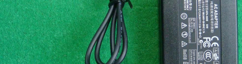
XTNTP9000
Nov 17, 2010ID Card Printer
Equipment Class
DXX - Part 15 Low Power Communication Device Transmitter