XU6-NFCRNFC Reader
Christie Digital Systems Canada, Inc.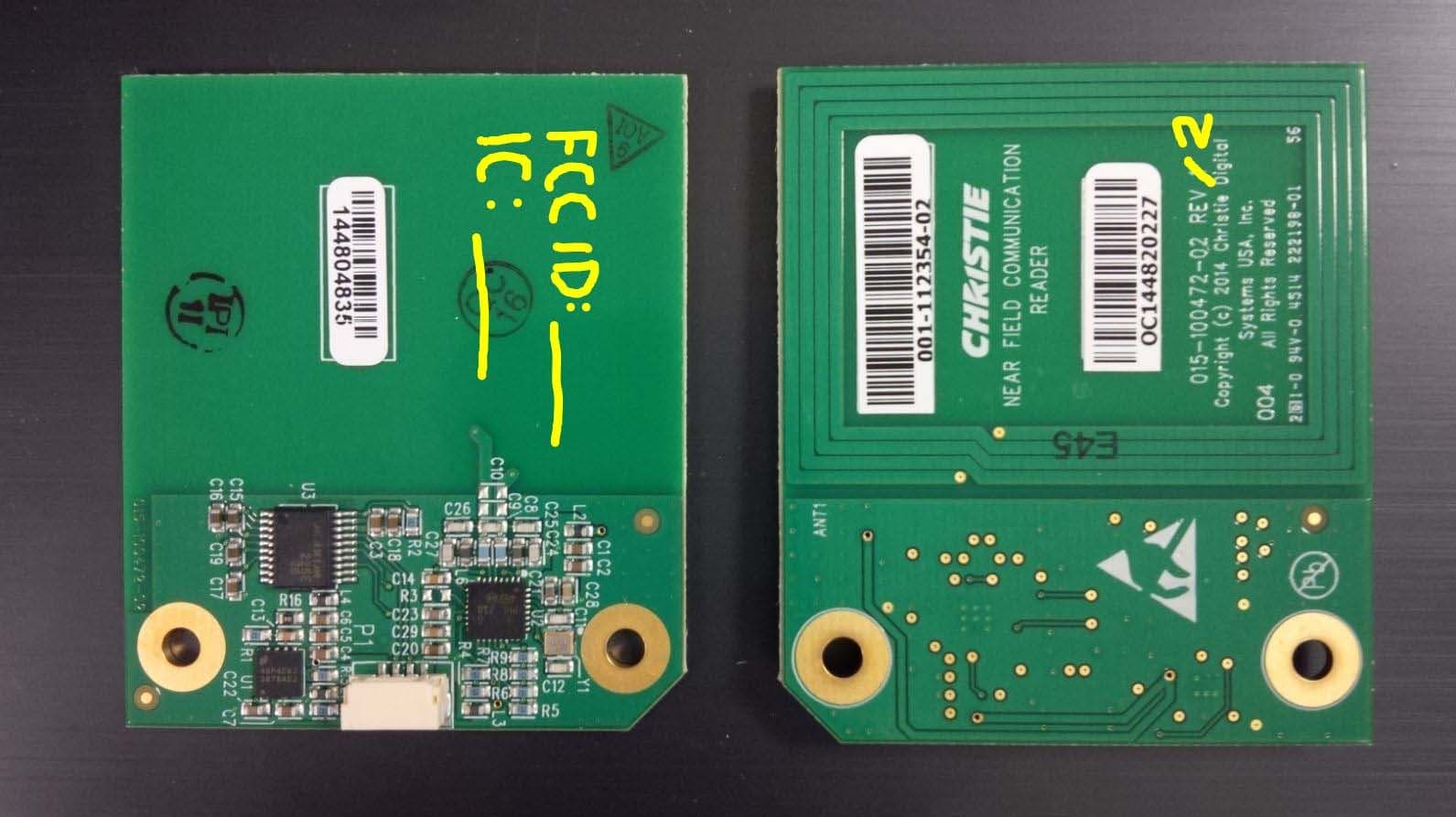
Click to zoom
Application Details
- Equipment Class
- DXX - Part 15 Low Power Communication Device Transmitter
- Date of Grant
- Jan 18, 2015
- Application Purpose
- Original Equipment
- Date of Application
- Jan 15, 2015
- Equipment Note
- NFC Reader
- Frequency Range
- 13.56000000 - 13.56000000
- Country
- Canada
Documents & Files
Document Text
Text extracted from the exhibit documents filed with the FCC. Open a document above to read the original.
Users Manual
Near Field Communications Reader ‐ Technical Reference Information Page 1 of 5 020‐101774‐01 Rev. 01 (December 2014) Near Field Communications Reader Technical Reference Information Description The Near Field Communications Reader (NCFR) module is a 13.56MHz transceiver designed to read Radio Frequency Identification (RFID) tags. This module is based on an ST Microelectronics CR95HF integrated transceiver that also embeds an Analog Front End (AFE) to provide the 13.56MHz air interface. The NCFR antenna is integrated into the circuit board so there is no external antenna required. Features Supports Write and Read 13.56MHz Integrated AFE Serial UART interface Integrated Antenna RoHS Compliant Near Field Communications Reader ‐ Technical Reference Information Page 2 of 5 020‐101774‐01 Rev. 01 (December 2014) Absolute Maximum Ratings (1) Rating Notes Min Max Units Supply Voltage P1 – Pin 1 ‐0.3 12 V UART Voltage P1 – Pin 2 and 3 ‐7 7 V Storage Temperature ‐25 85 °C Operating Temperature 0 70 °C (1) Stress beyond those listed under the Absolute Maximum Ratings may cause permanent damage to device. These are stress ratings only, and functional operation of the device at these or any other conditions beyond those indicated under Recommended Operating Conditions is not implied. Exposure to absolute‐maximum‐rated conditions for extended periods may affect device reliability. Recommended Operating Conditions Rating Notes Min Max Units Supply Voltage P1 – Pin 1 4.5 5.5 V V IL P1 – Pin 2 and 3 (UART) 0.8 V V IH P1 – Pin 2 and 3 (UART) 2 V Maximum Data Rate Supply Voltage of 5V 1000 kbps Pin Descriptions The NFCR board has a single four pin connector interface, identified by reference designator P1. Pin descriptions are given in the table below. Pin Name Type Description 1 PWR Power Supply Voltage 2 NFCR_TX Input RS‐232 Receiver Input 3 NFCR_RX Output RS‐232 Receiver Output 4 GND Power Ground Antenna The integrated antenna is etched in the copper on the top side of the circuit board. The antenna consists of four loops of 0.045” wide copper with 0.005” spacing. Near Field Communications Reader ‐ Technical Reference Information Page 3 of 5 020‐101774‐01 Rev. 01 (December 2014) Mechanical Dimensions Near Field Communications Reader ‐ Technical Reference Information Page 4 of 5 020‐101774‐01 Rev. 01 (December 2014) Notice This equipment has been tested and found to comply with the limits for a Class B digital device, pursuant to part 15 of the FCC/IC rules. These limits are designed to provide reasonable protection against harmful interference in a residential installation. This equipment generates, uses, and can radiate radio frequency energy and, if not installed and used in accordance with the instructions, may cause harmful interference to radio communications. However, there is no guarantee that interference will not occur in a particular installation. If this equipment does cause harmful interference to radio or television reception, which can be determined by turning the equipment off and on, the user is encouraged to try to correct the interference by one or more of the following measures: Reorient or relocate the receiving antenna. Increase the separation between the equipment and receiver. Connect the equipment into an outlet on a circuit different from that to which the receiver is connected. Consult the dealer or an experienced radio/TV technician for help. Warning: Changes or modifications not expressly approved by the Christie Digital Systems Canada Inc. could void the user's authority to operate the equipment. This device complies with Part 15 of the FCC/IC Rules. Operation is subject to the following two conditions: (1) this device may not cause interference and (2) this device must accept any interference received, including interference that may cause undesired operation of the device. Installation in end‐user equipment This device has been modularly approved and is intended solely for use in Christie Digital Systems products. Christie Digital Systems will retain control over the final installation of the device, such that compliance in the end‐user equipment is assured. The end‐user equipment will be tested for spurious and radiated emissions to ensure the end device complies with FCC Part 15 limits. Near Field Communications Reader ‐ Technical Reference Information Page 5 of 5 020‐101774‐01 Rev. 01 (December 2014) Labeling of end‐user equipment This device has been modularly approved. The manufacturer, product name, and FCC and Industry Canada identifiers of this product must appear on the outside label of the end‐user equipment as follows: Contains: FCC ID: XU6‐NFCR IC: 8691A‐NFCR
Cover Letter(s)
December 12, 2014 Ultratech Engineering Labs, Inc. 3000 Bristol Circle Oakville, Ontario L6H 6G4 Subject: Certification Application under FCC Part 15, Subpart C - Unlicensed Low Power Transmitter Operating in the Frequency Band 13.110-14.010 MHz. Applicant: Christie Digital Systems Canada Inc. Product: NFC Reader (NFCR) Model No.: NFCR FCC ID: XU6-NFCR Dear Sir/Madam: As appointed agent for Christie Digital Systems Canada Inc., we submit the application for equipment certification of the above product. Kindly review all files uploaded to your electronic filing site. If you have any queries, please do not hesitate to contact us. Yours truly, Dharmajit Solanki Dharmajit Solanki Authorized Agent UltraTech Group of Labs FCC TCB & IC CB Ultratech’s Accreditations: 0685 91038 1309 46390-2049 NVLAP LAB CODE 200093-0 SL2-IN-E-1119R Korea KCC-RRA CA2049 TL363_B TPTDP DA1300 3000 Bristol Circle, Oakville, Ontario, Canada L6H 6G4 Tel.: (905) 829-1570 Fax.: (905) 829-8050 Website: www.ultratech-labs.com Email: [email protected]
External Photos
ANNEX 2 – External Photos Christie Digital Systems Canada Inc. NFC Reader (NFCR) FCC ID: XU6-NFCR, IC: 8691A-NFCR A2 - 1
Internal Photos
ANNEX 3 – Internal Photos Christie Digital Systems Canada Inc. NFC Reader (NFCR) FCC ID: XU6-NFCR, IC: 8691A-NFCR A3 - 1
Test Report
NFC Reader (NFCR) Model: NFCR FCC ID: XU6-NFCR Applicant: Christie Digital Systems Canada Inc. 809 Wellington Street North Kitchener, Ontario Canada N2G 4Y7 In Accordance With Federal Communications Commission (FCC) Part 15, Subpart C Unlicensed Low Power Transmitter Operating in the Band 13.110-14.010 MHz UltraTech's File No.: CDS-501F15C225 This Test report is Issued under the Authority of Tri M. Luu Vice President of Engineering UltraTech Group of Labs Date: December 12, 2014 Report Prepared by: Dharmajit Solanki Issued Date: December 12, 2014 Tested by: Hung Trinh & Phuong Luu Test Dates: December 10 -11, 2014 The results in this Test Report apply only to the sample(s) tested, and the sample tested is randomly selected. This report must not be used by the client to claim product endorsement by NVLAP or any agency of the US Government. UltraTech 3000 Bristol Circle, Oakville, Ontario, Canada, L6H 6G4 Tel.: (905) 829-1570 Fax.: (905) 829-8050 Website: www.ultratech-labs.com , Email: [email protected], Email: [email protected] Korea KCC-RRA 91038 1309 46390-2049 NVLAP LAB CODE 200093-0 SL2-IN-E- 1119R CA2049 TL363_B TPTDP DA1300 FCC Part 15, Subpart C, Section 15.225 – Unlicensed Low Power Transmitter NFC Reader (NFCR), Model: NFCR FCC ID: XU6-NFCR ULTRATECH GROUP OF LABS File #: CDS-501F15C225 3000 Bristol Circle, Oakville, Ontario, Canada L6H 6G4 December 12, 2014 Tel. #: 905-829-1570, Fax. #: 905-829-8050, Email: [email protected] , Website: http://www.ultratech-labs.com All test results contained in this engineering test report are traceable to National Institute of Standards and Technology (NIST) TABLE OF CONTENTS EXHIBIT 1. INTRODUCTION .............................................................................................................................. 1 1.1. SCOPE ........................................................................................................................................................ 1 1.2. RELATED SUBMITTAL(S)/GRANT(S) ....................................................................................................... 1 1.3. NORMATIVE REFERENCES ..................................................................................................................... 1 EXHIBIT 2. PERFORMANCE ASSESSMENT ................................................................................................... 2 2.1. CLIENT INFORMATION ............................................................................................................................. 2 2.2. EQUIPMENT UNDER TEST (EUT) INFORMATION .................................................................................. 2 2.3. EUT’S TECHNICAL SPECIFICATIONS ...................................................................................................... 3 2.4. LIST OF EUT’S PORTS .............................................................................................................................. 3 2.5. ANCILLARY EQUIPMENT .......................................................................................................................... 3 EXHIBIT 3. EUT OPERATING CONDITIONS AND CONFIGURATIONS DURING TESTS ............................. 5 3.1. CLIMATE TEST CONDITIONS ................................................................................................................... 5 3.2. OPEPERATIONAL TEST CONDITIONS & ARRANGEMENT FOR TESTS ............................................... 5 EXHIBIT 4. SUMMARY OF TEST RESULTS ..................................................................................................... 6 4.1. LOCATION OF TESTS ................................................................................................................................ 6 4.2. APPLICABILITY & SUMMARY OF EMC EMISSION TEST RESULTS ....................................................... 6 4.3. MODIFICATIONS INCORPORATED IN THE EUT FOR COMPLIANCE PURPOSES ............................... 6 EXHIBIT 5. TEST DATA ..................................................................................................................................... 7 5.1. EMISSION BANDWIDTH [§15.215(C)] ........................................................................................................ 7 5.2. FIELD STRENGTH OF EMISSIONS WITHIN & OUTSIDE THE PERMITTED BAND 13.110-14.010 MHZ [47 CFR 15.225 (A) TO (D)] .................................................................................................................................... 10 5.3. FREQUENCY STABILITY [47 CFR 15.225(E)] ......................................................................................... 14 5.4. POWER LINE CONDUCTED EMISSIONS [47 CFR 15.107(A) & 15.207] ................................................ 16 EXHIBIT 6. MEASUREMENT UNCERTAINTY ................................................................................................ 19 6.1. LINE CONDUCTED EMISSION MEASUREMENT UNCERTAINTY ........................................................ 19 6.2. RADIATED EMISSION MEASUREMENT UNCERTAINTY ...................................................................... 19 FCC Part 15, Subpart C, Section 15.225 – Unlicensed Low Power Transmitter Page 1 of 19 NFC Reader (NFCR), Model: NFCR FCC ID: XU6-NFCR ULTRATECH GROUP OF LABS File #: CDS-501F15C225 3000 Bristol Circle, Oakville, Ontario, Canada L6H 6G4 December 12, 2014 Tel. #: 905-829-1570, Fax. #: 905-829-8050, Email: [email protected] , Website: http://www.ultratech-labs.com All test results contained in this engineering test report are traceable to National Institute of Standards and Technology (NIST) EXHIBIT 1. INTRODUCTION 1.1. SCOPE Reference: FCC Part 15, Subpart C, Section 15.225 - Operation within the band 13.110 - 14.010 MHz. Title: Code of Federal Regulations (CFR), Title 47 Telecommunication, Part 15, Subpart C - Intentional Radiators Purpose of Test: Equipment Certification for Devices in Section 15.225 - Operat…
Text truncated - open the document above for the full version.
Test Setup Photos
ANNEX 1 - TEST SETUP PHOTOS Christie Digital Systems Canada Inc. NFC Reader (NFCR), Model NFCR FCC ID: XU6-NFCR, IC: 8691A-NFCR A1 - 1 Power Line Conducted Emissions (Power Port) ANNEX 1 - TEST SETUP PHOTOS Christie Digital Systems Canada Inc. NFC Reader (NFCR), Model NFCR FCC ID: XU6-NFCR, IC: 8691A-NFCR A1 - 2 Power Line Conducted Emissions (Power Port) ANNEX 1 - TEST SETUP PHOTOS Christie Digital Systems Canada Inc. NFC Reader (NFCR), Model NFCR FCC ID: XU6-NFCR, IC: 8691A-NFCR A1 - 3 Radiated Emissions @ 10 m, Below 30 MHz, EUT is Position 1 ANNEX 1 - TEST SETUP PHOTOS Christie Digital Systems Canada Inc. NFC Reader (NFCR), Model NFCR FCC ID: XU6-NFCR, IC: 8691A-NFCR A1 - 4 Radiated Emissions @ 10 m, Below 30 MHz, EUT is Position 2 ANNEX 1 - TEST SETUP PHOTOS Christie Digital Systems Canada Inc. NFC Reader (NFCR), Model NFCR FCC ID: XU6-NFCR, IC: 8691A-NFCR A1 - 5 Radiated Emissions @ 3 m, above 30 MHz, EUT is Position 3
Contact Information
Applicant
Masud Attayi(Compliance Manager)
Test Firm
UltraTech Engineering Labs Inc.Tri Luu
Technical Specifications
| # | Rule Parts | Frequency Range | Power Output | Tolerance |
|---|---|---|---|---|
| 1 | 15C | 13.56 MHz - 13.56 MHz | - | 0.0100000000 % |
Other Applications from Christie Digital Systems Canada, Inc.
XU6-CRMX100
Dec 08, 2009ASSY PCB RF Module
Equipment Class
DTS - Digital Transmission System