XU9-FW2763PCDMA Rev A miniPCIe Data Module
Fusion Wireless
Click to zoom
Application Details
- Equipment Class
- PCB - PCS Licensed Transmitter
- Date of Grant
- Jan 17, 2011
- Application Purpose
- Original Equipment
- Date of Application
- Jan 16, 2011
- Equipment Note
- CDMA Rev A miniPCIe Data Module
- Frequency Range
- 1851.25000000 - 1908.75000000
- Company
- Fusion Wireless
- Country
- United States
Documents & Files
Document Text
Text extracted from the exhibit documents filed with the FCC. Open a document above to read the original.
Users Manual
Orca Mini PCI Express Card User Manual • USB Driver Installation 1. To install the VIA USB Windows device driver, you must first start the Setup application, VIA USB Drivers 2.1.5 (32-Bit).exe , by double-clicking the associated icon. 2. Choose the directory for the application to be installed. 3. Click Install, then this setup program will copy all the files into the directories on the local system drive of your PC. The following dialog box will appear upon execution. 4. Click Finish when this action has been completed. 5. Power up the notebook which has Orca PCIe data card installed inside. Then Windows will install all the related drivers automatically. You can find “VIA Telecom USB Modem”, “VIA Telecom AT Port”, “VIA Telecom LBS Port”, “VIA Telecom Voice Port” and “VIA Telecom USB ETS” in Device Manager. • Dial up Application Setup 1. Select “New Connection Wizard” 2. Select Connect to the Internet 3. Select “Set up my connection manually” 4. Select” Connect using a dial- up modem” 5. Enter your ISP name 6. Enter your Number to Dial 7. Select Anyone’s use 8. Enter user name and password 9. After finishing the configuration, you can set up a connection If Driver is properly installed, you can see “VIA Telecom USB Modem” in the properties menu. • RF Exposure Your device contains a transmitter and a receiver. When it is ON, it receives and transmits RF energy. When you communicate with your device, the system handling your connection controls the power level at which your device transmits. Important safety information regarding radio frequency radiation (RF) exposure. To ensure compliance with RF exposure guidelines the device must be used with a separation at 20cm or more from the body. Failure to observe these instructions could result in your RF exposure exceeding the relevant guideline limits. The maximum permissible exposure is defined in 47 CFR 1.1310 with 0.566 mW/cm*cm (CDMA800MHz) and 1 mW/cm*cm (CDMA 1900MHz). The transmitter uses an external antenna that should be installed away from nearby persons. The maximum permissible antenna gain is 9.9 dBi for CDMA800MHz and 9.2 dBi for CDMA 1900MHz. • Labeling Please add the phrase “Contains FCC Id XU9-FW2763P” to the product label of any device that includes this module
Cover Letter(s)
11555 Sorrento Valley Rd, Suite 202 October 15, 2010 San Diego, CA 92121 Nemko 11696 Sorrento Valley Rd. San Diego CA, 92121 USA Re: Request of Confidentiality for FCC ID: XU9-FW2763P Pursuant to Sections 0.457(d) and 0.459 of the Commission’s Rules, the Applicant hereby requests confidential treatment of information accompanying as outlined below: • Schematics • Bill of Material • Operating Description • Block Diagrams The above materials contain trade secrets and proprietary information not customarily released to the public. The public disclosure of these matters might be harmful to the Applicant and provide unjustified benefits to its competitors. The Applicant understands that pursuant to Rule 0.457(d)(I)(ii), disclosure of this Application and all accompanying documentation will not be made before the date of the Grant for this Application Sincerely,
Cover Letter(s)
Page 1 of 2 11555 Sorrento Valley Rd, Suite 202 October 15, 2010 San Diego, CA 92121 Nemko 11696 Sorrento Valley Rd. San Diego CA, 92121 USA Attn: Reviewing Engineer RE: PART 2 LICENSED MODULAR TRANSMITTER APPROVAL We, Fusion Wireless, hereby requests for licensed modular transmitter approval of our device, described as follows: Brand name: Fusion Wireless Model name: FW 2763p Type number: FCC ID: XU9-FW2763P In FCC Public Notice DA 00-1407 released June 26, 2000 there are eight numbered requirements that our device complies with: 1. The modular transmitter must have its own shielding. The DUT does provide RF shielding. Please refer to DUT picture. 2. The modular transmitter must have buffered modulation/data inputs The DUT has buffered data input it’s integrated in chip M36W0R6050T3ZAQ. 3. The modular transmitter must have its own power supply regulation The DUT has its own power supply regulation it’s integrated in PMIC chip 4. The modular transmitter must comply with the antenna requirements of Section 15.203 and 15.204c Only applies to Part 15 Unlicensed Transmitters. EUT is licensed transmitter module (22H/24E). 5. The modular transmitter must be tested in a stand-alone configuration The DUT was tested in a stand-alone configuration via a test kit. Please see section photographs of test configuration in the test report. Page 2 of 2 6. The modular transmitter must be labelled with its own FCC ID number Please see exhibition label sample for the FCC ID of this module. 7. The modular transmitter must comply with any specific rule or operating requirements applicable to the transmitter and the manufacturer must provide adequate instructions along with the module to explain any such requirements. The DUT is compliant with FCC Part 2, FCC Part 22, Subpart H and FCC Part 24 Subpart E. 8. The modular transmitter must comply with any applicable RF exposure requirements. The DUT is compliant with RF exposure requirement MPE evaluation. The MPE report is addressed in the RF exposure exhibition. Sincerely,
Cover Letter(s)
11555 Sorrento Valley Rd, Suite 202 October 15, 2010 San Diego, CA 92121 Nemko 11696 Sorrento Valley Rd. San Diego CA, 92121 USA RE: Operation of last transmit RF Power Amplifier FCC ID: XU9-FW2763p The final power amplifier produces a maximum of +23.8 dBm at the antenna port between the frequencies of 1850 MHz to 1910 MHz and 8424 MHz to 849 MHz inclusive. The Power amplifier is supplied from a 3.3V supply and draws 325 mA when generating maximum power The Transceiver’s frequency output and transmitted power level are controlled by the CDMA network; the user is not able to adjust these settings independently. Sincerely,
ID Label/Location Info
1 FCC ID: XU9-FW 2763P Date: November 12, 2010. FCC ID LABEL / LOCATION LABELLINGREQUIREMENTS PER §2.925 TheLabelshownshallbepermanentlyaffixed ataconspicuouslocationonthedeviceandbe readilyvisibletotheuseratthetimeofpurchase. See next page for label details. 2 FCC ID: XU9-FW 2763P Date: November 12, 2010.
Parts List/Tune Up Info
Tuning Procedure Please note: 1. The end user cannot tune or adjust output frequency or power level in any way. Frequency and power level are both controlled by software, as required by the CDMA cellular standard. 2. The voltage provided to the final PA stage is 3.0 V and the maximum current drawn is 900 mA 1: In FCC authorized lab, connect the DUT with callbox through a power splitter, the other port of splitter is connected to the spectrum to measure the Max power, Frequency error, etc... 2: DUT is controlled by the PC with the ETS tool, which is developed by VIA. Test Setting is shown as below. 3: Using ETS, Tx power can be set to the power level as what it can be on lab test requirement. After the connection is setup, ETS Command is located at RF\CDMA\DSPM Tx AGC Config\ In the window, Ctrl mode shall be set to Manual; Method shall be set to HW Value; DUT Power splitter Callbox Spectrum analyzer PC HW value can be adjusted from 0x000 to 0xfff to get the power wanted. Hyst State shall be set to mid Gain. Power(dBm): do not need to care. 4: By ETS, Channel can be set to the target channel to perform the test. After the connection is setup, ETS Command is located at RF\CP PSW PLL Channel Config\ In the window, Ctrl mode shall be set to Manual Band can be set to the band which is tested. Channel can be set to the channel which is tested. 5: For CDMA and EVDO switch, below ETS command can be used CP\VAL\PRI\Operating mode\CP Do Pref Mode Set&CP DO Hybrid Mode Set In CP Dp Pref Mode Set window, Op type shall be Parm Custom Value Prefered Mode shall be CDMA only for CDMA 1X test and HDR only for EVDO test In CP DO Hybrid Mode Set window, Optype shall be set to Parm Custom Value HybridMode shall be set to Non-Hybrid. 6: ETS is a tool which is developed by Via telecom, its name is engineering test system. With it, can spy the DUT’s status and control the DUT to work in different mode. Note: Conducted Tx power is designed to more than 23dBm.
RF Exposure Info
Evaluation of MPE limit at a given distance Equation from page 18 of OET Bulletin 65, Edition 97-01 where:S = power density P = power input to the antenna G = power gain of the antenna in the direction of interest relative to an isotropic radiator R = distance to the center of radiation of the antenna 22H24E Output power:23.98(dBm)Output power:23.75(dBm) Output power:0.250(W)Output power:0.237(W) Antenna gain:9.90(dBi)Antenna gain:9.20(dBi) Maximum antenna gain:9.77(numeric)Maximum antenna gain:8.32(numeric) Evaluation distance:20.00(cm)Evaluation distance:20.00(cm) Duty Cycle:100(%)Duty Cycle:100(%) Evaluation frequency:848.31(MHz)Evaluation frequency:1880.00(MHz) Limit from table below:0.566(mW/cm^2)Limit from table below:1.000(mW/cm^2) Power density:0.486(mW/cm^2)Power density:0.392(mW/cm^2) MARGIN:0.657(dB)MARGIN:4.063(dB) 2.1091EIRP:33.88(dBm)2.1091EIRP:32.95(dBm) ERP:31.73(dBm)ERP:30.8(dBm) ERP:1.49(W)ERP:1.20(W) ERP LIMIT:1.5(W)ERP LIMIT:3(W) MARGIN:0.03(dB)MARGIN:3.97(dB) 22.913ERP LIMIT:7.0(W)24.232EIRP LIMIT:2.0(W) ERP:1.49(W)EIRP:1.97(W) MARGIN:6.72(dB)MARGIN:0.06(dB) 2 4R PG S π = EUT complies FCC/LSGAC Local Official’s Guide to RF A LOCAL GOVERNMENT OFFICIAL'S GUIDE TO TRANSMITTING ANTENNA RF EMISSION SAFETY: RULES, PROCEDURES, AND PRACTICAL GUIDANCE
Test Report
Nemko USA, Inc. 11696 Sorrento Valley Rd., Suite F San Diego, CA 92121-1024 Phone (858) 755-5525 Fax (858) 452-1810 CERTIFICATION TEST REPORT Report Number: 2010 10158602 FCC Project Number: 59085-1 Nex Number: 137862 Applicant: Fusion Wireless 11555 Sorrento Valley Road, Suite 202 San Diego, CA 92121 Equipment Under Test (EUT): WIRELESS CELL MODULE Model: FW2763 P FCC ID: XU9-FW2763P IC ID: 8694A-FW2763P In Accordance With: FCC Part 22, Subpart H Industry Canada RSS-132, Issue 2 FCC Part 24 Subpart E RSS 133 Issue 5 and RSS GEN Issue 2 Tested By: Nemko USA Inc. San Diego, CA 92121 Date: January 14, 2011 Total Number of Pages: 36 Nemko USA, Inc. 11696 Sorrento Valley Road, Suite F, San Diego, CA 92121 Phone (858) 755-5525 Fax (858) 452-1810 FCC ID: XU9-FW2763P Report Number: 2010 10158602 FCC IC: 8649A-FW2763P Section1: Summary of Test Results General All measurements are traceable to national standards These tests were conducted on a sample of the equipment for the purpose of demonstrating compliance with FCC rules parts CFR47 Part 2 and 24 subpart E for the United States and RSS132 Issue 2, RSS133 Issue 5, and RSS-Gen Issue 2 for Canada. Radiated tests were conducted is accordance with ANSI C63.4- 2003. Radiated emissions are made on an open area test site. A description of the test facility is on file with the FCC and IC. The assessment summary is as follows: Apparatus Assessed: W IRELESS CELL MODULE Model: FW2763 P Serial: 100505 Specifications: FCC Part 22, Subpart H Industry Canada RSS-132, Issue 2, September 2005 FCC Part 2, Part 24 Subpart E RSS 133 Issue 5, February 2009 RSS-GEN Issue 2 Date Received in Laboratory: October 29, 2009 Compliance Status: Complies Exclusions: None Non-compliances: None Nemko USA, Inc. 11696 Sorrento Valley Road, Suite F, San Diego, CA 92121 Phone (858) 755-5525 Fax (858) 452-1810 FCC ID: XU9-FW2763P Report Number: 2010 10158602 FCC IC: 8649A-FW2763P 1.1 Report Release History REVISION DATE COMMENTS - January 14, 2011 Prepared By: Alan Laudani - January 14, 2011 Initial Release: Alan Laudani Note that the results contained in this report relate only to the items tested and were obtained in the period between the date of initial receipt of samples and the date of issue of the report. This test report has been completed in accordance with the requirements of ISO/IEC 17025. Nemko USA Inc. authorizes the applicant to reproduce this report provided it is reproduced in its entirety and for use by the company’s employees only. Any use which a third party makes of this report, or any reliance on or decisions to be made based on it, are the responsibility of such third parties. Nemko USA Inc. accepts no responsibility for damages, if any, suffered by any third party as a result of decisions made or actions based on this report. TESTED BY: __ Date: January 14, 2011 Alan Laudani, RF/EMC Engineer Nemko USA, Inc. 11696 Sorrento Valley Road, Suite F, San Diego, CA 92121 Phone (858) 755-5525 Fax (858) 452-1810 FCC ID: XU9-FW2763P Report Number: 2010 10158602 FCC IC: 8649A-FW2763P TABLE OF CONTENTS Section1: Summary of Test Results............................................................................ 2 1.1 Report Release History ........................................................................................ 3 Section 2: Equipment Under Test................................................................................ 5 2.1 Product Identification............................................................................................ 5 2.2 Technical Specifications of the EUT..................................................................... 5 Section 3: Test Conditions........................................................................................... 6 3.1 Test Environment ................................................................................................. 6 3.2 Test Equipment .................................................................................................... 6 Section 4: Observations ............................................................................................... 7 4.1 Modifications Performed During Assessment....................................................... 7 4.2 Record Of Technical Judgments .......................................................................... 7 4.3 EUT Parameters Affecting Compliance................................................................ 7 4.4 Test Deleted......................................................................................................... 7 4.5 Additional Observations ....................................................................................... 7 Section 5: Results Summary........................................................................................ 8 2.1 Test Result summary table................................................................................... 8 Appendix A: Test Results ............................................................................................ 9 A1. RF Power Output ................................................................................................. 9 A2. Occupied Bandwidth .......................................................................................... 16 A3. Spurious Emissions At Antenna Terminals........................................................ 22 A4. Field strength of Spurious Emissions ................................................................. 29 2.2 RSS 129 10.0 and RSS 133 6.7 Field Receiver Spurious Emissions ................ 29 A5. Receiver Spurious.............................................................................................. 37 Nemko USA, Inc. 11696 Sorrento Valley Road, Suite F, San Diego, CA 92121 Phone (858) 755-5525 Fax (858) 452-1810 FCC ID: XU9-FW2763P Report Number: 2010 10158602 FCC IC: 8649A-FW2763P Section 2: Equipment Under Test 2.1 Product Identification The Equipment Under Test was identified as follows:…
Text truncated - open the document above for the full version.
Test Setup Photos
Conducted Emissions frequency substitution EUT in Insulated box RE range measurements frequency stability/ output power peak frequency stability/ output power average
Contact Information
Applicant
David W Carey(President & CEO)
Technical Contact
Fusion WirelessBrian Richardson
[email protected]858-847-9611
11555 Sorrento Valley Road, Suite 202 · San Diego, California · United States
Non-Technical Contact
Fusion WirelessRolf Langli
[email protected]858-847-9611
Test Firm
Nemko USA, Inc. - San Diego EMC DivisionJan Blomgren
[email protected]760-444-3500
Technical Specifications
| # | Rule Parts | Frequency Range | Power Output | Emission | Tolerance |
|---|---|---|---|---|---|
| 2 | 24E | 1.85 GHz - 1.91 GHz | 237.00 mW | 1M38F9W | 31 Hz |
Other Applications from Fusion Wireless
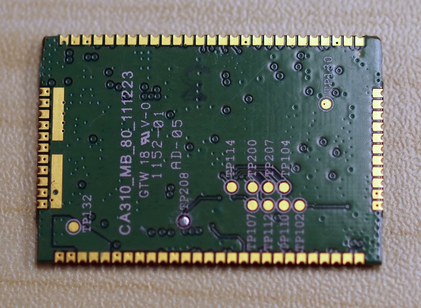
XU9-LISAC200
May 31, 2012CDMA 1xRTT Cellular Module
Equipment Class
PCB - PCS Licensed Transmitter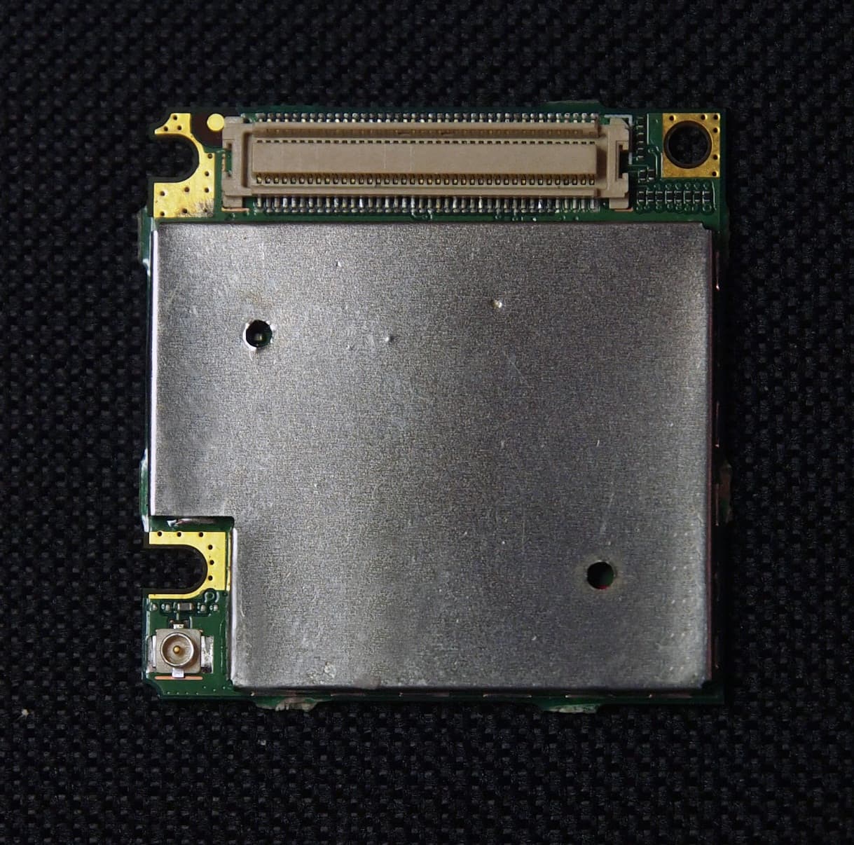
XU9-FW75
Apr 22, 2012CDMA 1xRTT Cellular Module
Equipment Class
PCB - PCS Licensed Transmitter