XUI10WT0001TWO-WAY RADIO
KONGTOP Industrial (Shenzhen) Co., Ltd.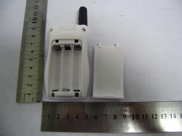
Click to zoom
Application Details
- Equipment Class
- FRF - Part 95 Family Radio Face Held Transmitter
- Date of Grant
- Mar 16, 2010
- Application Purpose
- Original Equipment
- Date of Application
- Mar 16, 2010
- Equipment Note
- TWO-WAY RADIO
- Frequency Range
- 462.56250000 - 467.71250000
- Country
- China
Documents & Files
Document Text
Text extracted from the exhibit documents filed with the FCC. Open a document above to read the original.
Users Manual
GMRS/FRS FREQUENCY CHART (MHz) CH. No. CH. Freq. CH. No. CH. Freq. CH. No. CH. Freq. 1 462.5625 9 467.5875 17 462.6000 2 462.5875 10 467.6125 18 462.6250 3 462.6125 11 467.6375 19 462.6500 4 462.6375 12 467.6625 20 462.6750 5 462.6625 13 467.6875 21 462.7000 6 462.6875 14 467.7125 22 462.7250 7 462.7125 15 462.5500 8 467.5625 16 462.5750 * Channels 8~14 are low-power FRS license free channels IMPORTANT NOTICE, FCC LICENSE REQUIRED FOR GMRS OPERATION The KT-100 Series operates on GMRS (General Mobile Radio Service) frequencies which require an FCC (Federal Communications Commission) license. You must be licensed prior to operating on channels 1 – 7 or 15 - 22, which comprise the GMRS channels of the KT-100 Series. Serious penalties could result for unlicensed use of GMRS channels, in violation of FCC rules, as stipulated in the Communications Act's Sections 501 and 502 (amended). You will be issued a call sign by the FCC which should be used for station identification when operating the radio on GMRS channels. You should also cooperate by engaging in permissible transmissions only, avoiding channel interference with other GMRS users, and being prudent with the length of their transmission time. To obtain a license or ask questions about the license application, contact the FCC at 1-888-CALL FCC or go to the FCC's website: http://www.fcc.gov and request form 605. FCC Warning To ensure that your expose to RF electromagnetic energy is Within the FCC allowable limits for occupational use, alwaysAdhere to the following guidelines: zDO NOT operate the radio without a proper antenna attached, as this may damaged the radio And may also cause you to exceed FCC RF exposure limits, A proper antenna is the antenna Supplied with this radio by the manufacturer or antenna specifically authorized by the manufacturer for use with this radio. zDO NOT transmits for more than 50% of total radio use time (“50% duty cycle). Transmitting more than 50% of the time can cause FCC RF exposure compliance requirements to be exceeded. The radio is transmitting when the “TX indicator” lights red. You can cause the radio to transmit by pressing the “PTT” switch. zALWAYS kepp the antenna at least 1.5cm (0.6 inch) away from the body when transmitting and Only use the belt-clip which is listed in instructions when attaching the radio to your belt, etc., to ensure FCC RF exposure compliance requirements are not exceeded. The information listed above provides the user with the information needed to make him or her aware of RF exposure, and what to do to as-sure that this radio operates with the FCC RF exposure limits of this radio. This device complies with Part 15 of the FCC Rules. Operation is subject to the following two conditions: (1) this device may not cause harmful interference, and (2) this device must accept any interference received, including interference that may cause undesired operation NOTE 1: This equipment has been tested and found to comply with the part 95 of the FCC rules. These limits are designed to provide reasonable protection against harmful interference in a residential installation. This equipment generates, uses and can radiate radio frequency energy and, if not installed and used in accordance with the instructions, may cause harmful interference to radio communications. However, there is no guarantee that interference will not occur in a particular installation. If this equipment does cause harmful interference to radio or television reception, which can be determined by turning the equipment off and on, the user is encouraged to try to correct the interference by one or more of the following measures: - Reorient or relocate the receiving antenna. - Increase the separation between the equipment and receiver. -Connect the equipment into an outlet on a circuit different from that to which the receiver is connected. -Consult the dealer or an experienced radio/TV technician for help. Any changes or modifications not expressly approved by the manufacturer could void the user’s authority to operate the equipment. The information listed above provides the user with the information needed to make him or her aware of RF exposure, and what to do to assure that this radio operates with the FCC RF exposure limits of this radio.
External Photos
KONGTOP Industrial (Shenzhen) Co., Ltd. Model: KT-100 REPORT NO.: STR10028030I FCC PART 95 EXHIBIT 2 - EUT EXTERNAL PHOTOGRAPHS EUT View 1 EUT View 2 KONGTOP Industrial (Shenzhen) Co., Ltd. Model: KT-100 REPORT NO.: STR10028030I FCC PART 95 EUT View 3 EUT View 4 KONGTOP Industrial (Shenzhen) Co., Ltd. Model: KT-100 REPORT NO.: STR10028030I FCC PART 95 EUT View 5 EUT View 6
ID Label/Location Info
KONGTOP Industrial (Shenzhen) Co., Ltd. Model: KT-100 REPORT NO.: STR10028030I FCC PART 95 EXHIBIT 1- PRODUCT LABELING Proposed FCC ID Label Format FCC ID: XUI10WT0001 Specifications : Text is Black in color and justified. Labels are printed in indelible ink on permanent adhesive silk-screened onto the EUT or shall be affixed at a conspicuous location on the EUT. Proposed Label Location on EUT FCC ID Label Location
ID Label/Location Info
KONGTOP Industrial (Shenzhen) Co., Ltd. Model: KT-100 REPORT NO.: STR10028030I FCC PART 95 EXHIBIT 1- PRODUCT LABELING Proposed FCC ID Label Format FCC ID: XUI10WT0001 Specifications : Text is Black in color and justified. Labels are printed in indelible ink on permanent adhesive silk-screened onto the EUT or shall be affixed at a conspicuous location on the EUT. Proposed Label Location on EUT FCC ID Label Location
Internal Photos
KONGTOP Industrial (Shenzhen) Co., Ltd. Model: KT-100 REPORT NO.: STR10028030I FCC PART 95 EXHIBIT 3 - EUT INTERNAL PHOTOGRAPHS EUT Housing and Board View Solder Board-Component View 1 KONGTOP Industrial (Shenzhen) Co., Ltd. Model: KT-100 REPORT NO.: STR10028030I FCC PART 95 Solder Board-Component View 2
Parts List/Tune Up Info
1 / 2 Item name Description Qty Location T100V1 SMT 1 IC AME8800BEET 3.0V 300mA /SOT-23 "AME"(ROHS) 1 U6 2 IC AT24C02N /SOP "ATMEL"(ROHS) 1 IC2 3 IC MC34119D SOP-8(ROHS) 1 U2 4 IC RDA1845 QFN(6*6)(ROHS) 1 U1 5 IC JT5BZ0-7F91/CHIP MASK(ROHS) 1 IC1 6 Chip Resistor 0R ±5% 1/16W 0603(ROHS) 4 JP1 R38 R30 R20 7 Chip Resistor 10R ±5% 1/16W 0603(ROHS ) 1 R27 8 Chip Resistor 1K ±5% 1/16W 0603(ROHS ) 1 R15 9 Chip Resistor 10K ±5% 1/16W 0603(ROHS ) 3 R1 R5 R9 10 Chip Resistor 100K ±5% 1/16W 0603(ROHS ) 21 R6 R8 R16 R17 R23 R26R31 R32 R33 R39 R41 R42R43 R44 R45 R46 R47 R48R54 R51 R19 11 Chip Resistor 1M ±5% 1/16W 0603(ROHS) 4 R10 R18 R21 R49 12 Chip Resistor 12K ±5% 1/16W 0603(ROHS) 2 R7 R37 13 Chip Resistor 1.5M ±5% 1/16W 0603(ROHS) 2 R35 R36 14 Chip Resistor 18K ±5% 1/16W 0603(ROHS) 1 R11 15 Chip Resistor 2K ±5% 1/16W 0603(ROHS ) 1 R52 16 Chip Resistor 2.2K ±5% 1/16W 0603(ROHS ) 1 R14 17 Chip Resistor 27K ±5% 1/16W 0603(ROHS) 1 R25 18 Chip Resistor 47R ±5% 1/16W 0603(ROHS) 2 R56 R57 19 Chip Resistor 470R ±5% 1/16W 0603(ROHS) 1 R3 20 Chip Resistor 4.7K ±5% 1/16W 0603(ROHS ) 1 R24 21 Chip Resistor 47K ±5% 1/16W 0603(ROHS ) 4 R13 R22 R28 R55 22 Chip Resistor 6.8K ±5% 1/16W 0603(ROHS) 1 R4 23 Chip Resistor 8.2K ±5% 1/16W 0603(ROHS) 1 R2 24 Chip Resistor 82K ±5% 1/16W 0603(ROHS) 1 R29 25 Chip Resistor 820K ±5% 1/16W 0603(ROHS) 1 R12 26 Chip capacitor C0G 8PF ±0.5P 50V 0603 SAMSUNG(ROHS ) 1C5 27 Chip capacitor C0G 10PF ±0.5P 50V 0603 SAMSUNG(ROHS ) 2 C3 C16 28 Chip capacitor C0G 100PF ±5% 50V 0603 SAMSUNG(ROHS ) 4 C14 C20 C33 C62 29 Chip capacitor 0.001UF ±10% 50V 0603 TDK(ROHS ) 10 C8 C17 C19 C34 C39 C46C47 C56 C57 C58 30 Chip capacitor 0.01UF ±10% 50V 0603 TDK(ROHS ) 1 C31 31 Chip capacitor 0.1UF +80-20% 16V 0603 TDK(ROHS ) 12 C12 C13 C18 C21 C35 C38C40 C45 C49 C52 C53 C65 32 Chip capacitor 1UF +80-20% 16V 0603 (ROHS ) 1 C37 33 Chip capacitor 10UF +80-20% 10V 0805 TDK(ROHS) 5 C9 C41 C59 C60 C26A 34 Chip capacitor C0G 12PF ±5% 50V 0603 SAMSUNG(ROHS ) 3 C4 C55 C64 35 Chip capacitor C0G 15PF ±5% 50V 0603 SAMSUNG(ROHS ) 2 C6 C63 2 / 2 Item name Description Qty Location 36 Chip capacitor C0G 18PF ±5% 50V 0603 SAMSUNG(ROHS) 1 C7 37 Chip capacitor C0G 20PF ±5% 50V 0603 SAMSUNG(ROHS ) 1 C11 38 Chip capacitor 270PF ±10% 50V 0603 TDK(ROHS) 1 C22 39 Chip capacitor C0G 33PF ±5% 50V 0603 SAMSUNG(ROHS) 3 C15 C43 C44 40 Chip capacitor 470PF ±10% 50V 0603 TDK(ROHS ) 1C1 41 Chip capacitor 680PF ±10% 50V 0603 TDK(ROHS) 1 C30 42 Chip capacitor 0.068UF ±10% 16V 0603 TDK(ROHS) 4 C23 C25 C29 C36 43 Chip capacitor 820PF ±10% 50V 0603 TDK(ROHS) 1 C24 44 tantalum capacitor acitor 10UF ±20% 10V A "AVX"(ROHS) 1 C51 45 tantalum capacitor acitor 22UF ±20% 10V A (ROHS) 1 C50 46 Trimmer capacitor 10PF ±10% 2PIN 3X3mm(ROHS) 1 VC1 47 Chip Diode BA592 SOD323 (ROHS) 3 D1 D2 D3 48 Chip Diode IN4148 /SOD-323(ROHS) 2 D4 D6 49 Chip transistor 2SA1162/SOT-23(ROHS) 2 Q3 Q5 50 Chip transistor 2SC4177 SOT323 (ROHS) 1 Q4 51 Chip transistor 2SC4226 SOT323 (ROHS) 1 Q2 52 FET 2SK3078/SOT-89(ROHS) 1 Q1 53 Chip inductor 10NH 0603 PANASONIC(ROHS ) 1L9 54 Chip inductor 18NH 0603 PANASONIC(ROHS) 2 L5 L8 55 Chip inductor 22NH 0603 PANASONIC(ROHS) 1 L2 56 Chip inductor 27NH 0603 PANASONIC(ROHS) 1 L1 57 Chip inductor 47NH 0603 PANASONIC(ROHS) 1 L4 58 Chip inductor 5.6NH 0603 PANASONIC(ROHS ) 1L6 59 Chip Air Coil φ 0.3*1.0*4T(ROHS) 1 L3 60 Chip Air Coil φ 0.3*1.0*5T(ROHS) 1 L7 61 PCB T100 R1 71x40x1.0mm FR4 ( ROHS ) 1 63 electrolytic capacitor acitor 220UF ±20% 10V 6X5mm(ROHS) 1 C32 64 LED 0805 BLUE(ROHS) 1 LED1 65 Crystal 12.8M 15pF TC=5ppm 49US ( ROHS ) 1Y2 66 Crystal 4MHz +-0.5% 30pF 2PIN ( ROHS ) 1Y1 67 microphone D6xH2.7mm -62dB±2dB 2PIN L=2.8mm(ROHS) 1 U7 68 earphone jack EJ-2502B 2.5mm ( DY-1301 ) (ROHS) 1J1 69 wire D=0.4mm L=50(4+4)mm RED ( ROHS ) 1 SP+ 70 wire D=0.4mm L=50(4+4)mm GREEN ( ROHS ) 1 SP-
Parts List/Tune Up Info
KONGTOP INDUSTRIAL (SZ) CO.,LTD Manufactor Guide TO:Marketing department□、R&D ■、PMC□、Purchasing department□、Quality control department■、 Project department■、Production department■ Page: 1 OF 5 MODEL KT-100 No. Order No. DEPARTMENT R&D Department Sulotion Quantity DATE 2009-11-17 Version V1 Leadtime KT-100 Manufactor Guide Transmit Test Test Condition: inpout Voltage:4.5V,Channel CH1=462.5625MHz 一、Transmit electric current: 1 Test Items:Transmit electric current: 2、 instrument: Ammeter、DC Power 3、Test Methods Connect the ammeter, press PTT,test the transmet current: ≤370mA 二、Transmit frequency and power 1、Test Items: Transmit frequency Transmit power 2、 instrument: HP8921 Cell Site Test Set、DC Power 3、Test Methods 3.1 Turn on the instrument to the transmit status,frequency is : 462.5625MHz 3.2 Turn off the Audio Signal Generator function of HP8921 Cell Site Test Set 3.3 Press PTT ,adjust the frequency by VC,ranges: 462.5625MHZ±500HZ 3.4 Inspecting the transmit power: between 25 ~ 27dBm. 三、Transmit modulattion and distortion 1、Test Items:Transmit modulattion and distortion 2、 instrument: HP8921 Cell Site Test Set、DC Power 3、Test Methods 3.1 Turn on the instrument to the transmit status,frequency is : 462.5625MHZ,Input the Audio signal(1KHZ/50MV) on TP11 spot. 3.2 Set the terminal to CH1, CTCSS OFF on Transmit status. 3.3 Inspecting the modulation limiting between 2.0--2.5 KHz 3.4 Inspecting the distortion : < 5% 3.5 Inspecting SNR: > 38dB 3.6 Audio requency response 3.6.1 Input the Audio signal(1KHZ/50MV) on TP11 spot.Press PTT. Change another audio signal frequency,compare with 1KHZ 500Hz: 0.76KHZ ±0.2KHZ 2.5KHz: 2.1KHZ.±0.2KHZ (Filter Setting HPF 50Hz LPF 15KHz PK +-/2) Designed by Check Approval date 2009-11-17 date date KONGTOP INDUSTRIAL (SZ) CO.,LTD Manufactor Guide TO:Marketing department□、R&D ■、PMC□、Purchasing department□、Quality control department■、 Project department■、Production department■ page: 2 OF 5 MODEL KT-100 No. Order No. DEPARTMENT R&D Department Sulotion Quantity DATE 2009-11-17 Version V1 Leadtime KT-100 Manufactor Guide 六:ACP Test 1、Test Items:ACP 2、 instrument: HP8921 Cell Site Test Set、DC Power 3、Test Methods: 3.1 Turn on the instrument to the transmit status,frequency is : 462.5625MHz 3.2 Set the terminal to CH1, CTCSS OFF on Transmit status.; 3.3 Set the output Audio Signal frequency as 1.25KHZ, level as 150Mv.on HP8921 Cell Site Test Set 3.4 Enter the menu of ACP on HP8921 Cell Site Test Set,Press PTT 3.5 measure and note the ACP data: ≤-58dB Filter Setting HPF 50Hz LPF 15KHz PK +-/2 七、 CTCSS modulattion deviation 1. Test Items: CTCSS modulattion deviation 2. instrument: HP8921 Cell Site Test Set、DC Power 3. Test Methods: 3.1 Turn on the instrument to the transmit status,frequency is : 462.5625MHz 3.2 Set the terminal to CH1, CTCSS 01 on Transmit status. 3.3 Turn off the Audio Signal Generator function of HP8921 Cell Site Test Set 3.4 Press PTT 3.5 Measure and note the deviation between 0.3~0.65KHZ on HP8921 Cell Site Test Set; modulattion frequency is :67HZ Filter Setting HPF 50Hz LPF 300Hz PK +-/2 六:VOX test 1、Test Items:VOX 2、instrument: HP8921 Cell Site Test Set、DC Power、 Low-frequency signal Generator 3、Test Methods: 3.1 Input the Audio signal(1KHZ/50MV) on TP11 spot 3.2 Set the terminal to CH1,VOX level1 (or level2,level3) 3.3:Change the output level of AF,Inspect the terminal meet the fllowing: A、at vox sens level 1 15 ±2mV B、at vox sens level 2 10±2 mV C、at vox sens level 3 5±2 mV 八:CALL modulattion deviation 1. Test Items: CALL modulattion deviation 2. instrument: HP8921 Cell Site Test Set、DC Power 3. Test Methods 3.1 Set the terminal to CH1, CTCSS 01 on Transmit status 3.2Inspecting the CALL modulattion deviation between 1.2—1.7 KHz Designed by Check Approval date 2009-11-17 date date KONGTOP INDUSTRIAL (SZ) CO.,LTD Manufactor Guide TO:Marketing department□、R&D ■、PMC□、Purchasing department□、Quality control department■、 Project department■、Production department■ Page: 3 OF 5 MODEL KT-100 No. Order No. DEPARTMENT R&D Department Sulotion Quantity DATE 2009-11-17 Version V1 Leadtime KT-100 Manufactor Guide Receiver Test Test Condition: inpout Voltage:4.5V,Channel CH1=462.5625MHz 一、 Receive AUDIO signal test 1、 Test Items:AUDIOoutput、AUDIO distortion、AUDIO S/N、Audio requency response 2、 instrument: HP8921 Cell Site Test Set、DC Power 3、 Test Methods 3.1 Turn on the instrument to the receiving status,set frequency as : 462.5625MHz,RF level output as -47dBm and 1.5K frequency deviation,1KHZ modulattion signal. 3.2 Set the terminal to CH1, CTCSS OFF, turn the VOL to the MAX. 3.3 Inspecting the MAX AUDIO output: ≥ 1.4V 3.4 Adjust the VOL to let the AUDIO output as 0.9V,inspect the distortion: ≤ 5% 3.5 Inspecting the AUDIO S/N:≥45 dB. 4、 3.6 Inspecting the Audio requency response( compare with 1KHZ) 500Hz: + 3.0 dB ~ +7.0 dB. 2.5KHz: -9.0 dB ~ –15.0 dB. Filter Setting HPF 50Hz LPF 15KHz PK +-/2 二、Receiver sensitivity test 1、Test Items:Receiver sensitivity 2、 instrument: HP8921 Cell Site Test Set、DC Power 3、Test Methods: 3.1 Turn on the instrument to the receiving status,set frequency as : 462.5625MHz,RF level output as -47dBm and 1.5K frequency deviation,1KHZ modulattion signal. 3.2 Set the terminal to CH1, CTCSS OFF, SQ to level 1. 3.3 Adjust the output level,let the SNR is 12Db. 3.4 Inspect the RF level after adjust,it’s Receiver sensitivity : ≤-118dBm Filter Setting HPF 50Hz LPF 15KHz PK +-/2 三. SQL sensitivity test 1、 Test Items:SQL sensitivity test 2、 instrument: HP8921 Cell Site Test Set、DC Power、 Oscilloscope 3、 Test Methods: 3.1 Turn on the instrument to the receiving status,set frequency as : 462.5625MHz,RF level output as -47dBm and 1.5K frequency deviation,1KHZ modulattion signal 3.2 Set the terminal to CH1, CTCSS OFF, SQ to level 1. turn the VOL to the MAX.; 3.3 Adjust the output level, LET the AUDIO output as Waveform 3.4 Inspect the RF level after adjust,it’s SQL sensitivity: ≤-118dBm SQ: (1-6level) the same test method. Designed by Check Approval Da…
Text truncated - open the document above for the full version.
RF Exposure Info
RF EXPOSURE EXHIBIT Standard Applicable According to FCC KDB 447498 clause 5, the power thresholds and operating conditions in the following table 1 are used to determine SAR test requirements for PTT radios required to comply with the general population exposure limit. . Evaluation: RF Exposure Conditions: The two-way radio device is intended for use in the Body-worn exposure condition and the General Population / Uncontrolled RF exposure environment, and always kepp the antenna at least 1.5cm (0.6 inch) away from the body Transmission Mode: The two-way radio device utilizes a FM modulation with Push-to talk mode. Duty Cycle: The two-way radio device utilizes a FM modulation with a duty cycle of 50% when actual operating duty factor is ≤ 50 %. RF Output Power Tx frequency range: 462.5500~462.7250MHz (GMRS) 462.5625~462.7125MHz (FRS) 467.5625~467.7125MHz (FRS) Antenna-to-tissue separation: 2.5 mm Maximum Output Power: 25.75dBm(375.837mW) Maximum Duty Factor: 50% Source-based time-averaged conducted output power is 188.365 mW = < 200 mW
Test Report
KONGTOP Industrial (Shenzhen) Co., Ltd. Model: KT-100 REPORT NO.: STR10028030I PAGE 1 OF 28 FCC PART 95 FCC PART 95 MEASURMENT AND TEST REPORT For KONGTOP Industrial (Shenzhen) Co., Ltd. Xinwuyuan Industrial Area, Gushu, Xixiang, Baoan, Shenzhen, P.R. China FCC ID: XUI10WT0001 Report Concerns: Original Report Equipment Type: two-way radio Model: KT-100 Report No.: STR10028029I Test/Witness Engineer: Test Date: 2010-02-22 to 2010-02-26 Issue Date: 2010-03-09 Prepared By: SEM.Test Compliance Service Co., Ltd 3/F, Jinbao Commerce Building, Xin'an Fanshen Road, Bao'an District, Shenzhen, P.R.C.(518101) Approved & Authorized By: Jandy So / PSQ Manager Note: This test report is limited to the above client company and the product model only. It may not be duplicated without prior permitted by SEM.Test Compliance Service Co., Ltd . KONGTOP Industrial (Shenzhen) Co., Ltd. Model: KT-100 REPORT NO.: STR10028030I PAGE 2 OF 28 FCC PART 95 TABLE OF CONTENTS 1. GENERAL INFORMATION ...................................................................................................................................3 1.1 PRODUCT DESCRIPTION FOR EQUIPMENT UNDER TEST (EUT)...............................................................................3 1.2 TEST STANDARDS...................................................................................................................................................3 1.3 RELATED SUBMITTAL(S)/GRANT(S) .......................................................................................................................4 1.4 TEST METHODOLOGY.............................................................................................................................................4 1.5 TEST FACILITY.......................................................................................................................................................4 1.6 EUT EXERCISE SOFTWARE....................................................................................................................................4 1.7 ACCESSORIES EQUIPMENT LIST AND DETAILS.......................................................................................................4 1.8 EUT CABLE LIST AND DETAILS.............................................................................................................................4 2. SUMMARY OF TEST RESULTS ...........................................................................................................................5 3. §2.1046 AND §95.639(A) (1) & (D)- RF OUTPUT POWER..................................................................................6 3.1 STANDARD APPLICABLE.........................................................................................................................................6 3.2 TEST EQUIPMENT LIST AND DETAIL.......................................................................................................................6 3.3 TEST PROCEDURE...................................................................................................................................................6 4.4 ENVIRONMENTAL CONDITIONS..............................................................................................................................7 3.4 TEST RESULT/PLOTS..............................................................................................................................................7 4. §2.1049 AND § 95.633(A) & (C) - OCCUPIED BANDWIDTH OF EMISSION .................................................8 4.1 STANDARD APPLICABLE.........................................................................................................................................8 4.2 TEST EQUIPMENT LIST AND DETAILS.....................................................................................................................8 4.3 TEST PROCEDURE...................................................................................................................................................8 4.4 ENVIRONMENTAL CONDITIONS..............................................................................................................................9 4.5 TEST RESULTS/MASKS...........................................................................................................................................9 5. §95.635(B)- UNWANTED RADIATED EMISSION ............................................................................................11 5.1 MEASUREMENT UNCERTAINTY............................................................................................................................11 5.2 STANDARD APPLICABLE.......................................................................................................................................11 5.3 TEST EQUIPMENT LIST AND DETAILS...................................................................................................................11 5.4 TEST PROCEDURE.................................................................................................................................................11 5.5 ENVIRONMENTAL CONDITIONS............................................................................................................................12 5.6 SUMMARY OF TEST RESULTS/PLOTS....................................................................................................................12 6. §2.1055, §95.621 (B) AND §95.627(B)- FREQUENCY STABILITY ..................................................................20 6.1 STANDARD APPLICABLE.......................................................................................................................................20 6.2 TEST EQUIPMENT LIST AND DETAILS...................................................................................................................20 6.3 TEST PROCEDURE..................................................................................…
Text truncated - open the document above for the full version.
Test Setup Photos
KONGTOP Industrial (Shenzhen) Co., Ltd. Model: KT-100 REPORT NO.: STR10028030I FCC PART 95 EXHIBIT 4 - TEST SETUP PHOTOGRAPHS Radiation Spurious Emission Test Setup (30MHz to 1GHz) Radiation Spurious Emission Test Setup (Above 1GHz) KONGTOP Industrial (Shenzhen) Co., Ltd. Model: KT-100 REPORT NO.: STR10028030I FCC PART 95 Frequency Stability Test Setup
Contact Information
Applicant
Awa Cheung(Manager)
Test Firm
SEM.Test Compliance Service Co., Ltd.Jandy So
Technical Specifications
| # | Rule Parts | Frequency Range | Power Output | Emission | Tolerance |
|---|---|---|---|---|---|
| 2 | 95B | 462.5625 MHz - 467.7125 MHz | 380.00 mW | 11K0F3E | 2.5 ppm |
Other Applications from KONGTOP Industrial (Shenzhen) Co., Ltd.
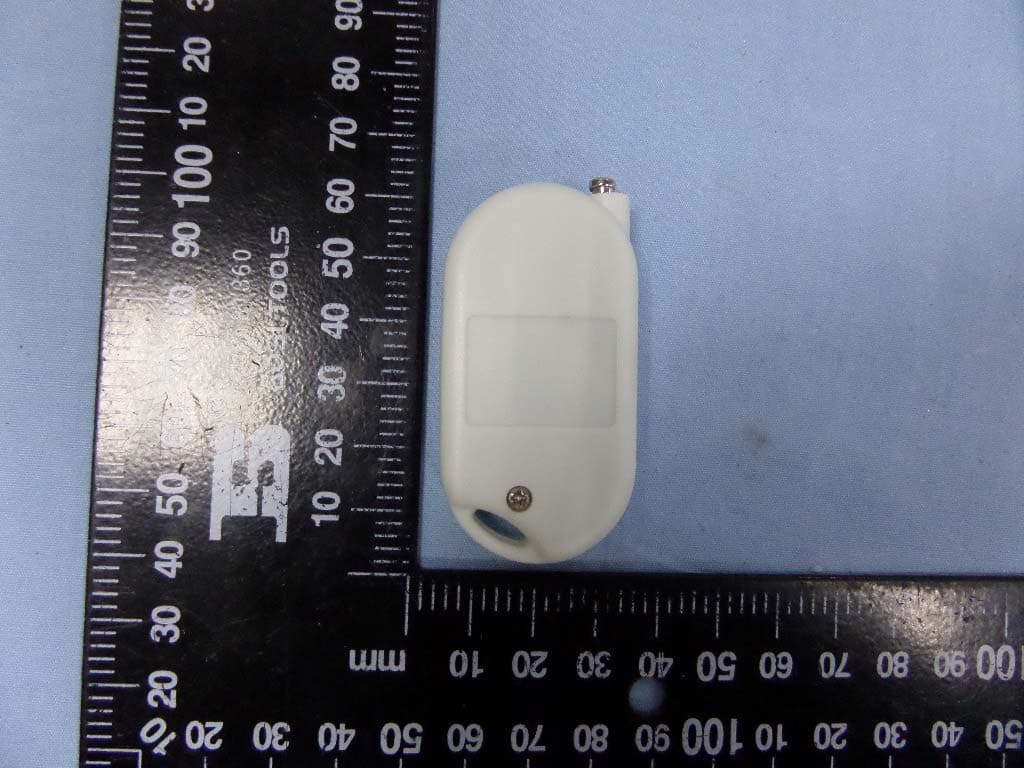
XUIRL712S
Nov 15, 2015Remote controller
Equipment Class
DSC - Part 15 Security/Remote Control Transmitter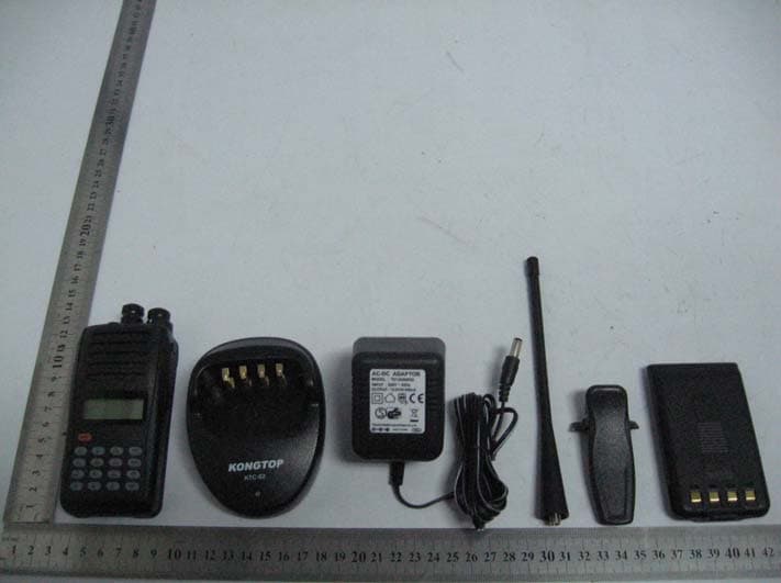
XUI09WT0001
Jan 06, 2010TWO-WAY RADIO
Equipment Class
TNF - Licensed Non-Broadcast Transmitter Held to Face