XUX-CON-M200-USA1Mobile RFID 4 Port Data Collection Device
ChronoTrack Systems LLC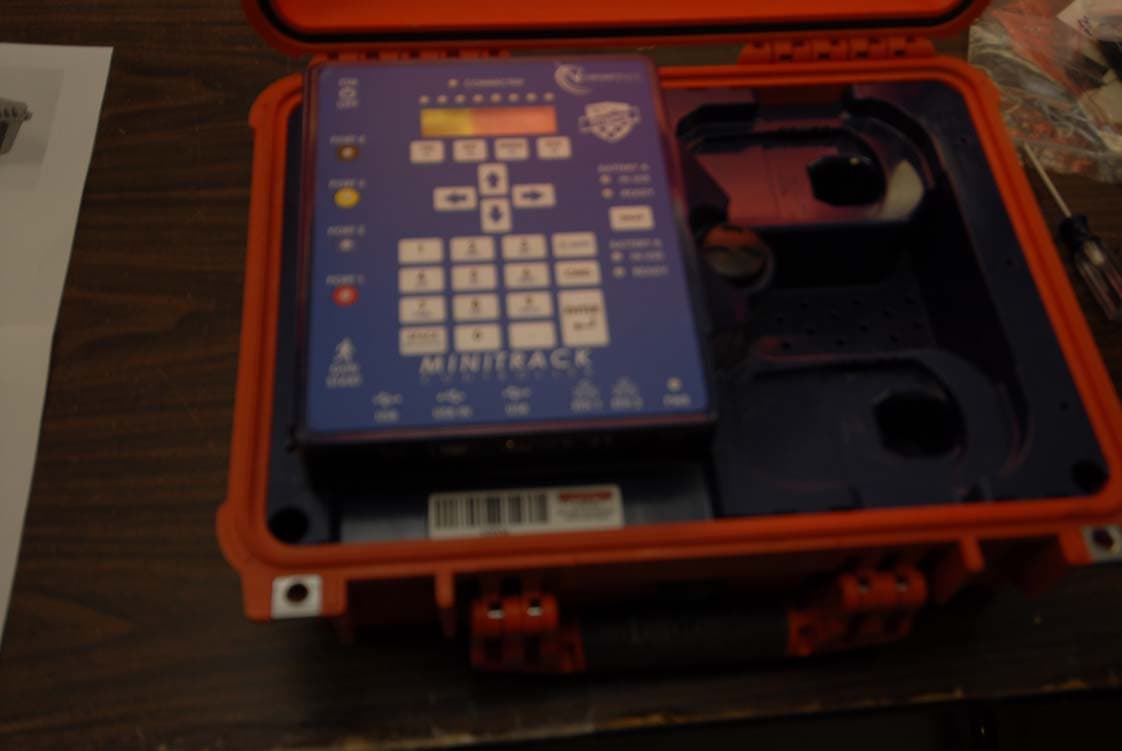
Click to zoom
Application Details
- Equipment Class
- DSS - Part 15 Spread Spectrum Transmitter
- Date of Grant
- Jul 26, 2012
- Application Purpose
- Original Equipment
- Date of Application
- Jul 23, 2012
- Equipment Note
- Mobile RFID 4 Port Data Collection Device
- Frequency Range
- 902.75000000 - 927.25000000
- Company
- ChronoTrack Systems LLC
- Country
- United States
Documents & Files
Document Text
Text extracted from the exhibit documents filed with the FCC. Open a document above to read the original.
Users Manual
Updated: May 2012 1 Document # 12471 MiniTrack User Manual ChronoTrack Systems, Inc. 111 East Diamond Avenue Evansville, Indiana 47711 U.S.A. 812-423-7800 Main 314-406-7243 Sales 812-759-7877 Support 812-423-7801 Fax www.chronotrack.com Updated: May 2012 i © Copyright 2012 ChronoTrack Systems, Inc. All rights reserved. “ChronoTrack”, “MiniTrack”, “D-Tag”, “B-Tag”, and “D-Tag Interrogator” are trademarks of ChronoTrack Systems, Inc. “Windows” is a registered trademark of Microsoft Corporation in the United States and other countries. All other trademarks used herein are property of their respective owners. ChronoTrack Systems, Inc. makes no warranty of any kind with regard to this material, including, but not limited to, the implied warranties of merchantability and fitness for a particular purpose. ChronoTrack Systems shall not be liable for errors contained herein or for incidental or consequential damages in connection with the furnishing, performance, or use of this material. This document contains proprietary information, which is protected by copyright. No part of this document may be photocopied, reproduced, or translated into another language without the prior written consent of ChronoTrack Systems. ChronoTrack Systems shall not be liable for technical or editorial errors or omissions contained herein. The information is provided “as is” without warranty of any kind and is subject to change without notice. ChronoTrack Systems, Inc. MiniTrack User Manual Index Updated: May 2012 ii Table of Contents 1. Introduction ...................................................................................................................................................... 1 1.1 Applicable Version .................................................................................................................................... 1 1.2 About This Guide ...................................................................................................................................... 1 1.3 MiniTrack System Overview ...................................................................................................................... 1 1.4 Cautions and Warnings ............................................................................................................................. 2 2. Gator Setup and Configuration .......................................................................................................................... 3 2.1 Possible Gator Configurations ................................................................................................................... 3 2.2 Positioning and Linking Gators .................................................................................................................. 3 2.3 Creating a “Dead Zone” ............................................................................................................................ 4 3. Controller Setup ................................................................................................................................................ 5 3.1 The Controller Interface ............................................................................................................................ 5 3.2 Powering ON ............................................................................................................................................ 5 3.3 Checking Connected Antennas .................................................................................................................. 6 3.4 Swap Battery Power ................................................................................................................................. 6 4. Using the MiniTrack Controller .......................................................................................................................... 7 4.1 The Main Screen ....................................................................................................................................... 7 4.2 Menu Navigation ...................................................................................................................................... 8 4.3 Menu Commands ..................................................................................................................................... 9 4.3.1 Creating a Gun Start Timestamp ................................................................................................................10 4.3.2 Viewing Messages .....................................................................................................................................10 4.3.3 Setting File Markers ..................................................................................................................................10 4.3.4 Server Configuration .................................................................................................................................10 4.3.5 Tools ........................................................................................................................................................11 4.3.6 Low Power ................................................................................................................................................12 4.3.7 Dry Mode .................................................................................................................................................12 4.3.8 Setting the Time and Date .........................................................................................................................13 4.3.9 Audio Menu ..............................................................................................................................................14 4.3.10 Network Configuration ..............................................................................................................................14 4.3.11 Temperature.................................…
Text truncated - open the document above for the full version.
Users Manual
•ChronoTrack Components •ChronoTrack Setup •ChronoTrack Read Zone & Handling Unwanted Reads •Available ChronoTrack Resources •Approximate weight: 30/26 lbs for 800/400 •Supports up to 28 ft. timing lines per controller •Multiple communication options: LAN, WiFi and Cellular •Redundant Data Collection/Storage •Redundant Power: Operates on AC, Aux Power and Internal Batteries with seamless transfer •Touch Panel Interface •Does not require tuning, highly resistant to interference Controller Three main components: Touch Panel Computer (TPC) Mesa, Connection Mesa and the power brick . Beeper is located to the left of the TPC with the WiFi Antennas. Touch Panel Computer (TPC) Mesa Main interface, top clear panel to easily check for SIM card and status lights. Cellular antenna connects to the right side of the TPC mesa. Controller Power Button Located on the back side of the TPC mesa Connection Mesa Color coded for antenna connections. Contains 2 LAN connections, 2 USB ports, the aux power connection and makes the main power connection from the power brick. Antenna Connections BNC and color coded, not required to match colors but best for troubleshooting Aux Power and Ethernet Connections Each controller has a 2 port Ethernet switch, uses standard network cables. Auxiliary power connection for use with battery cable, supports 12-30V. USB Connections USB Ports are powered, however they do not support USB 2.0 – test hardware before use for compatibility AC connection on power brick Located towards the back of the controller Magnetic Lid Props Prevents lid from being slammed on cables, provides ventilation •Approximate weight: 16 lbs (with Batteries) •Supports up to 14 ft timing lines per controller •Communication via LAN –Note: WiFi and Cellular available with add-on devices. •Redundant Power: Operates on AC and Ryobi Drill with seamless transfer •Keypad interface. •Does not require tuning, highly resistant to interference •Approximate weight: 27/12 lbs for Full/Mini •Approximate length: 42/36” for Full/Mini •Modular line configurations: Up to 56’ lengths •Low profile, yet extremely rugged and durable •Easy to handle and pack •Can setup along side of the road and turn into place for late road closures •Strong enough to protect hardware and cables even for large vehicles Interrogator (Gator) Handle located on back side of gator •Durable/rugged with replaceable pigtail cables •Pigtails can be used to route cables in either direction in the gator •Separate component from gator so that if damaged you don’t have to replace both at the same time •High quality RF cable •BNC for quick/easy setup •Color coded and bundled in sets of 4 •CAUTION – Any changes or modifications to this system without the express permission of ChronoTrack Systems will void the user’s authority to operate this equipment. •As a professional installer you must: –Use only ChronoTrack approved antennae –Use only ChronoTrack approved cables –Use only ChronoTrack approved accessories •Read-zone: begins around two meters in front of the line •Reads tags repeatedly over a 5 second time period •Only reports a single time in the 5 second window, when it “best” saw the tag •Not collecting tags at the end of the race, creating additional reads as finishers collect at timing points to cheer on or wait for other participants •Unique lines within a close proximity of each other require shielding from each other •Instructional materials: flyers and videos •ChonoTrack Timers Web Portal •Manual and Guides - BoxScore’s Main Screen - Configuring the controller for your event - Set and sync times - Removing data with a thumb drive - Error alerts - Sample race - Advanced modes and features BoxScore - Main Screen BoxScore – Point Configuration On startup and accessible in the Configure menu •Time sets go out to all controllers on the wired/wireless network •Can either set a new time or set the current time •Best to set the controllers to another source, time resolution on controller display will be less accurate •Controllers should be left one once time is set BoxScore – Time Management Accessible via the System menu BoxScore – Time Entry Screen •Controller saves data to a single file from power on to off •Use thumb drives under 2 gigabytes (larger USB drives take to long for the OS to index) •Data is saved to a folder based on the current point name with a file name based on the power up time
Users Manual
CHRONOTRACK SYSTEMS CORP. PRODUCT AND SERVICE ACQUISITION AGREEMENT This agreement is entered into as of this ____ day of _____________, 201__ by and between Chronotrack Systems Corp., having a place of business at 111 E. Diamond Avenue, Evansville, Indiana 47711 (“ChronoTrack”) and ______________________________________, having a place of business at ___________________________________________________________ (“Customer”). The parties are entering into this Agreement for the provision of UHF RFID tags for use in timing races that will or may be conducted by Customer. The parties hereto agree as follows: 1. Customer agrees to purchase all UHF RFID tags for any races customer may time, using Chronotrack’s race timing equipment, at the then-current price for such tags from Chronotrack. a. In the normal course of business Chronotrack agrees to limit price increases of UHF RFID tags to no more than the Consumer Price Index in any one calendar year. If, however, Chronotrack can show an increase in its costs for UHF RFID tags that exceed 10% in any calendar year, Chronotrack reserves the right to renegotiate the price of UHF RFID tags during the life of this contract. If the parties are unable to agree on a new price, Chronotrack may, at its option, increase its price by the amount its costs increased by more than ten percent (10%) in any calendar year. b. If through no fault of the Customer, Chronotrack fails to fulfill a Customer’s order for UHF RFID tags, and, provided Customer’s order was received in a timely manner, Chonotrack will not unreasonably withhold permission for Customer to use a third party’s UHF RFID tags on a one-time basis. Such request must be made and acknowledged in writing using FAX or email. 2. Chronotrack shall bill such orders promptly and in the usual course of business. Customer will use reasonable business efforts to advise Chronotrack of customer’s anticipated needs for such UHF RFID tags. Chronotrack will use its best efforts to meet all delivery schedules requested by customer. Payment shall be due within thirty (30) days of the invoice date. Any invoice not paid within ninety (90) days of the invoice date shall be subject to late fees in the amount of one percent (1%) per month. In addition, Customer shall be responsible for all attorney fees and costs of collection incurred by Chronotrack in collecting any past due invoices. 3. Chronotrack hereby grants to customer a non-exclusive right and license for a one-time use of the UHF RFID tags purchased and related technology. Chronotrack retains all rights, title and interest in the technology related to the use of the UHF RFID for timing of races. All rights not expressly granted herein are retained by Chronotrack. a. The license granted hereby is for a single use of each UHF RFID tag purchased from Chronotrack. Multiple use of any UHF RFID tag is not permitted and constitutes a violation of the terms of the license. b. The grant of the license for use of the UHF RFID tags purchased from Chronotrack is conditioned upon at least one (1) representative of Customer successfully completing Chronotrack’s official training session. Until at least one (1) representative of Customer has successfully completed Chronotrack’s official training session, Customer shall not be permitted to purchase any UHF RFID tags pursuant to this Agreement and is not authorized to install or operate the Chronotrack race timing equipment c. Customer acknowledges that it must use Chronotrack’s UHF RFID tags in races conducted by Customer using any of Chronotrack’s race timing equipment. 4. Chronotrack represents and warrants that the equipment shall be free from defects in material and workmanship at the time of delivery, installation and performance thereof for a period of one (1) year for professional series equipment and for a period of ninety (90) days for mini-series equipment. If during the applicable warranty period following delivery to customer, service is required with respect to any Chronotrack systems provided, Chronotrack shall provide warranty service or replacement, at Chronotrack’s option, at its facilities in Evansville, Indiana. Customer shall be responsible for the cost of returning shipment to Chronotrack and Chronotrack will be responsible for ground shipment following service and/or replacement of the product. During the above warranty periods Chronotrack will make a good faith effort to provide loaner timing systems for Customer systems that are being serviced under warranty. Shipment of such loaner equipment will be at Customer’s expense. EXCEPT FOR THE WARRANTIES PROVIDED ABOVE, CHRONOTRACK DISCLAIMS ALL OTHER WARRANTIES, EXPRESS OR IMPLIED, TO THE MAXIMUM EXTENT PERMITTED BY APPLICABLE LAW, INCLUDING ANY WARRANTIES OF MERCHANTABILITY OR FITNESS FOR A PARTICULAR USE. IN NO EVENT SHALL CHRONOTRACK BE LIABLE FOR ANY DIRECT, SPECIAL, PUNITIVE, OR CONSEQUENTIAL DAMAGES, INCLUDING WITHOUT LIMITATION LOSS OF PROPERTY, ARISING FROM OR RELATED TO THIS AGREEMENT REGARDLESS OF THE FORM OF ACTION EVEN IF CHRONOTRACK WAS INFORMED OF THE POSSIBILITY OF SUCH DAMAGES. 5. Upon expiration the above warranty periods Chronotrack will make available a support/ service contract that will cover software upgrades and hardware repair. Chronotrack will also offer a fee based loaner system for equipment that is being serviced. As long as replacement parts are available, Chronotrack will continue to offer service and support on all Chronotrack timing equipment for at least one (1) year after announcing end-of-life on any equipment. In the event replacement parts are no longer available, Chronotrack may substitute parts or will offer for sale a comparable timing system capable of using Customer’s inventory of Chronotrack provided UHF RFID disposable tags. 6. In the event customer breaches this Agreement by using Chronotrack timing equipment to time a race and does not use authorized UHF RFID tags purchased from Chronotrack or re-uses single use t…
Text truncated - open the document above for the full version.
Cover Letter(s)
30 April 2012 To Whom It May Concern: We hereby delegate CKC Certification Services, LLC (CKC CS) power of attorney to act on our behalf in matters pertaining to certification of products. The actions of CKC CS shall be considered the same as our own. Sincerely, Daniel R. Howell Daniel R. Howell President Chronotrack Systems Corp Phone: 812-759-7870 E-Mail: [email protected]
Cover Letter(s)
30 April 2012 Federal Communications Commission 7435 Oakland Mills Road Columbia, MD 21046 Subject: Request for Permanent Confidentiality To whom it may concern: In accordance with 47CFR Section 0.457 and Section 0.459 pertaining to confidential material, we hereby request to hold permanently confidential all information contained within the below identified exhibits/document categories submitted pursuant to radio equipment certification requirements for FCC ID: XUX-CON-M200-USA1 1. Block Diagram 2. Operational Description 3. Schematics The above material contains trade secrets and proprietary information as specified by 47CFR 0.457(d) and technical data, which would customarily be guarded from competitors. The public disclosure of this information might be harmful to our company and provide unjustified benefits to our competitors. Sincerely, Daniel R. Howell Daniel R. Howell President ChronoTrack Systems Corp Phone: 812-759-7870 E-Mail: [email protected]
Cover Letter(s)
30 April 2012 Federal Communications Commission 7435 Oakland Mills Road Columbia, MD 21046 Subject: Request for Temporary Confidentiality To whom it may concern: In accordance with 47CFR Section 0.457 and Section 0.459, FCC Public Notice DA04- 1705 and KDB Publication 726920 pertaining to confidential material, we hereby request to hold temporarily confidential all information contained within the below identified exhibits/document categories submitted pursuant to radio equipment certification requirements for FCC ID: XUX-CON-M200-USA1 for 180 days. 1.) All Internal Photos 2.) All External Photos 3.) All Manuals The above material contains trade secrets and proprietary information as specified by 47CFR 0.457(d) and technical data, which would customarily be guarded from competitors. Pre-marketing public disclosure of the information might be harmful to our company and provide unjustified benefits to our competitors. Sincerely, Daniel R. Howell Daniel R. Howell President ChronoTrack Systems Corp Phone: 812-759-7870 E-Mail: [email protected]
Cover Letter(s)
Satisfying 15.203 - Justifying Profession Installation for Chronotrack approved antennae Q: How is the product marketed, restricted or otherwise limited from use by the general public. How is the product marketed to preclude use by the general public? A: This system (transmitter and bundled choice of approved antennae) is only marketed and sold to verified established professional race timers, not to the general public. Q: What guidance, training or contracts are in place to ensure that professional installers are adequately trained. A: To complete a system sale, our customers are required (by contract) to attend a one-day training class, which includes warnings about using only approved antennae and accessories with the system. The user manual and sales contract also include warnings and reminders of the restriction to approved antennae and accessories. Q: Again, what is special about the product that would require the equipment to be professionally installed? A: This product is "special" only in that it is relatively complex system in terms of overall system setup, yet it provides relatively narrow functionality (RFID tag presence in a given field at a given time) of little interest to the general public. Additional Use-Case Reminder Limited Application and Scope of Equipment. This product is temporarily installed in public spaces (roadways, parks, etc.) for brief periods (generally under 8 hours) for RFID reading during an event.
ID Label/Location Info
ChronoTrack Mobile RFID Controller MODEL: 200 Series FCC ID: XUX-CON-M200-USA1 IC: 8688A-CONM200USA1 ChronoTrack Systems Corp This device complies with Part 15 of FCC Rules. Operation is subject to the following two conditions: (1) this device may not cause harmful interference, and (2) this device must accept any interference received, including interference that may cause undesired operation.
Internal Photos
Impinj IPJ‐REV External Photos Rear View Front View Top View Bo;om View
Internal Photos
Impinj IPJ‐REV Internal Photos PCB Top PCB Bo9om
RF Exposure Info
Page 1 of 8 Report No: 91963-16 LP100045_RFX Report Form_Rev 0 RADIO FREQUENCY EXPOSURE REPORT FOR THE Device: ChronoTrack Time Keeping Device Model: Revolution Report No.: 91963-16 Date of issue: July 19, 2012 PREPARED FOR: ChronoTrack Systems 111 East Diamond Ave. Evansville IN 47711 PREPARED BY: Randy Clark CKC Laboratories, Inc. 5046 Sierra Pines Drive Mariposa, CA 95338 Page 2 of 8 Report No: 91963-16 Purpose: To demonstrate compliance with United States, Canada and/or European Union RF Exposure requirements for Portable equipment (devices used ≤20cm from the body) or Mobile equipment (devices used >20cm from the body) with power output below exemption levels and Mobile equipment, where Maximum Permissible Exposure (MPE) Calculations apply. United States Compliance Requirements (1.1310): RF Exposure Evaluation Limits Occupational / Controlled Exposure Frequency Range (MHz) Electric Field Strength (V/m) Magnetic Field Strength (A/m) Power Density (mW/cm 2 ) Averaging Time (minutes) 0.3-3.0 614 1.63 *(100) 6 3.0-30 1842/f 4.89/f *(900/f 2 ) 6 30-300 61.4 0.163 1 6 300-1500 --- --- f/300 6 1500-100,000 --- --- 5.0 6 RF Exposure Evaluation Limits General Population / Uncontrolled Exposure Frequency Range (MHz) Electric Field Strength (V/m) Magnetic Field Strength (A/m) Power Density (mW/cm 2 ) Averaging Time (minutes) 0.3-1.34 614 1.63 *(100) 30 1.34-30 824/f 2.19/f *(180/f 2 ) 30 30-300 27.5 0.073 0.2 30 300-1500 --- --- f/1500 30 1500-100,000 --- --- 1.0 30 * Plane wave equivalent power density Limit is calculated based on the mid-band frequency used in the operating frequency range. Exemption Level: Power output <60/f GHz (mW) Page 3 of 8 Report No: 91963-16 Canadian Compliance Requirements (RSS-102): RF Exposure Evaluation Limits Occupational / Controlled Exposure: Frequency Range (MHz) Electric Field Strength (V/m) Magnetic Field Strength (A/m) Power Density (W/m 2 ) Averaging Time (minutes) 0.003-1.0 600 4.9 --- 6 1.0-10 600/f 4.9/f --- 6 10-30 60 4.9/f --- 6 30-300 60 0.163 10 6 300-1500 3.54 f 0.5 0.0094*f 0.5 f/3 6 1500-15,000 137 0.364 50 6 15,000-150,000 137 0.364 50 616000/f 1.2 RF Exposure Evaluation Limits General Population / Uncontrolled Exposure Frequency Range (MHz) Electric Field Strength (V/m) Magnetic Field Strength (A/m) Power Density (W/m 2 ) Averaging Time (minutes) 0.003-1.0 280 2.19 --- 6 1.0-10 280/f 2.19/f --- 6 10-30 28 2.19/f --- 6 30-300 28 0.073 2 6 300-1500 1.585 * f 0.5 0.0042 * f 0.5 f/150 6 1500-15,000 61.4 0.163 10 6 15,000-150,000 61.4 0.163 10 616000/f 1.2 *Power density limit applicable >100MHz Exemption Level: Frequency Range (MHz) Maximum Output Power (Conducted or EIRP) 0.003-1000 ≤ 200 mW 1000-2200 ≤ 100 mW 2200-3000 ≤ 20 mW 3000-6000 ≤ 10 mW Page 4 of 8 Report No: 91963-16 European Union Compliance Requirements (ICNIRP): RF Exposure Evaluation Limits Occupational / Controlled Exposure: Frequency Range (MHz) Electric Field Strength (V/m) Magnetic Field Strength (A/m) Power Density (W/m 2 ) Averaging Time (minutes) 0.00082-0.065 610 24.4 --- 6 0.065-1.0 610 1.6/f --- 1.0-10 610/f 1.6/f --- 6 10-400 61 0.16 10 6 400-2000 3.0 * f 0.5 0.008 * f 0.5 f/40 6 2000-300,000 137 0.36 50 6 RF Exposure Evaluation Limits General Population / Uncontrolled Exposure Frequency Range (MHz) Electric Field Strength (V/m) Magnetic Field Strength (A/m) Power Density (W/m 2 ) Averaging Time (minutes) 0.003-0.150 87 5.0 --- 6 0.150-1.0 87 0.73/f -- 6 1.0-10 87/f 0.5 0.73/f --- 6 10-400 28 0.073 2 6 400-2000 1.375 f 0.5 0.0037*f 0.5 f/200 6 2000-300,000 61 0.16 10 6 *Power density limit applicable >100MHz Exemption Level: Power output < 20mW 1 1 May vary by product type Page 5 of 8 Report No: 91963-16 Device and Antenna Operating Configuration: Device operating at maximum output power with continuous transmission of modulated data. Output power set to maximum. Maximum antenna gain used: 5dBi. Test Procedure: This equipment is evaluated in accordance with the guidelines set forth in OET Guide 65 & ANSI C95.1 for the US and Health Canada Safety Code 6 & RSS 102 for Canada. Other Considerations: Calculations do not include cable losses, power averaging effects, averaging due to frequency hopping, or spatial averaging as antennas are multiplexed. Intended use for product is fixed temporary installations. Bystanders are transient to the equipment installation. Page 6 of 8 Report No: 91963-16 MPE Calculations Applicability: Limit Used X General Population / Uncontrolled Exposure Occupational / Controlled Exposure RF Exposure Exemption Yes United States Yes Canada No Europe Equipment operational details: Config # Operating Frequency (MHz) Measured Output Power (dBm) Antenna Gain (dBi) Antenna Type / Configuration EIRP (dBm) 1 902-928 30 5 Panel 35 Measurements based from EMC Test Report(s): 91963-8, FC09-014, FC09-014A MPE Calculation: 2 4d EIRP DensityPower Given: EIRP in mW or W and d in cm or m Config # Distance (cm) US (1.1310) Canada (RSS-102) EU (ICNIRP) Power Density (mW/cm 2 ) Limit (mW/cm 2 ) Power Density (W/m 2 ) Limit (W/m 2 ) Power Density (W/m 2 ) Limit (W/m 2 ) 1 20.3 0.61 0.61 6.1 6.1 -- -- Page 7 of 8 Report No: 91963-16 Summary: Exemptions: In the case the equipment meets compliance requirements by exemption the product is approved for use under mobile or portable conditions without further testing under the condition that any additional collocation or simultaneous transmission requirements (including necessary separation distances) have been met. MPE Calculation Results: In the case the equipment meets compliance by MPE Calculations the product is approved for use under mobile conditions without further testing under the condition that any additional collocation or simultaneous transmission requirements (including necessary separation distances) have been met. It is assumed that the manufacturer shall design the equipment such that the minimum separation distance of 20cm (or greater, as listed above) is met or that the manufacturer provides a protection…
Text truncated - open the document above for the full version.
Test Report
This report contains a total of 24 pages and may be reproduced in full only. Partial reproduction may only be done with the written consent of CKC Laboratories, Inc. ChronoTrack Systems TEST REPORT FOR ChronoTrack Time Keeping Device, Revolution Tested To The Following Standards: FCC Part 15 Subpart C Sections 15.207 & 15.247 Report No.: 91963‐8 Date of issue: July 6, 2011 This test report bears the accreditation symbol indicating that the testing performed herein meets the test and reporting requirements of ISO/IEC 17025 under the applicable scope of EMC testing for CKC Laboratories, Inc. We strive to create long‐term, trust based relationships by providing sound, adaptive, customer first testing services. We embrace each of our customers’ unique EMC challenges, not as an interruption to set processes, but rather as the reason we are in business. Page 2of 24 Report No.: 91963‐8 TABLE OF CONTENTS Administrative Information ........................................................................................................................................... 3 Test Report Information ............................................................................................................................................ 3 Report Authorization ................................................................................................................................................. 3 Test Facility Information ............................................................................................................................................ 4 Site Registration & Accreditation Information .......................................................................................................... 4 Summary of Results ................................................................................................................................................... 5 Conditions During Testing ......................................................................................................................................... 5 Equipment Under Test ............................................................................................................................................... 6 Peripheral Devices ..................................................................................................................................................... 6 FCC Part 15 Subpart C .................................................................................................................................................... 7 15.207 AC Mains Conducted Emissions ..................................................................................................................... 7 15.247(d) Radiated Spurious Emissions ................................................................................................................... 15 Supplemental Information .......................................................................................................................................... 23 Measurement Uncertainty .............................................................................................................…
Text truncated - open the document above for the full version.
Contact Information
Applicant
Daniel Radcliff Howell(President)
Technical Contact
ChronoTrack Systems LLCDaniel R Howell
[email protected]812-759-7870
111 East Diamond Ave · Evansville, Indiana · United States
Test Firm
CKC Laboratories, Inc.Steve Behm
Technical Specifications
| # | Rule Parts | Frequency Range | Power Output |
|---|---|---|---|
| 1 | 15C | 902.75 MHz - 927.25 MHz | 1 W |
Other Applications from ChronoTrack Systems LLC

XUX-CON-M800-USA1
Mar 04, 2010MC627 Timekeeping System
Equipment Class
DSS - Part 15 Spread Spectrum Transmitter
XUX-CON-M400-USA1
Mar 04, 2010MC627 Timekeeping System
Equipment Class
DSS - Part 15 Spread Spectrum Transmitter