XVBX1C01TPM Sensor
Standard Motor Products, Inc.
Click to zoom
Application Details
- Equipment Class
- DSC - Part 15 Security/Remote Control Transmitter
- Date of Grant
- Mar 10, 2011
- Application Purpose
- Original Equipment
- Date of Application
- Mar 08, 2011
- Equipment Note
- TPM Sensor
- Frequency Range
- 315.00000000 - 315.00000000
- Country
- United States
Documents & Files
Document Text
Text extracted from the exhibit documents filed with the FCC. Open a document above to read the original.
Users Manual
WARNING Read and review all instructions, illustrations and warnings if included or follow manufacturer recommended service and replacement procedures before installing. Professional Installation Only. Improper installation may result in the failure of the motor vehicle Tire Pressure Monitoring System (“TPMS”) Sensor to operate properly. REMOVAL 1) The tire and wheel assembly removal must be followed as outlined in the vehicle manufacturer’s Service Manual. INSTALLATION Part assembly sequence is shown in Figure 1. 1) Insert the valve portion of the TPM sensor in the valve hole until contact is made between seal and wheel rim. 2) When the valve is completely inserted, maintain the sensor contact with the wheel rim and manually screw the nut for a few turns. 3) While maintaining the sensor and valve in position, engage the socket on the nut and run the nut down to a torque of 8.0 Nm (71 in-lbs.). 4) The sensor is correctly mounted according to the following criteria: Seal is pressed against the outer surface of the wheel rim’s hole. Sensor housing is positioned against the rim’s drop well and contacting at least in one point. Sensor housing should not exceed the rim’s hump height. 5) The tire and wheel assembly installation must be followed as outlined in the vehicle manufacturer’s Service Manual. FCC and IC Notice This Class B digital apparatus complies with Part 15 of the FCC Rules and with RSS-210 and IC ES-003 of the Industry Canada Rules. Operation is subject to the following two conditions: (1) This device may not cause harmful interference, and (2) This device must accept any interference received, including interference that may cause undesired operation. Warning: Any changes or modifications in construction of this device which are not expressly approved by the party responsible for compliance could void the user’s authority to operate the equipment. MISE EN GARDE: Lire attentivement et passer en revue les instructions, les illustrations et les mises en garde, le cas échéant, ou suivre les procédures de réparation ou de remplacement recommandées par le fabricant avant de procéder à l’installation. L’installation doit être faite uniquement par des professionnels. Une installation incorrecte peut entraîner une défaillance du capteur du système de detéction de pression des pneus (« TPMS »). DÉPOSE 1) Suivre le mode de dépose de la roue figurant dans le Guide d’entretien du constructeur du véhicule. INSTALLATION La séquence d’assemblage des pièces est illustrée à la Figure 1. 1) Insérer la valve du capteur de surveillance de la pression des pneus (TPM) dans l’orifice de valve, jusqu’à ce qu’un contact soit fait entre le joint et la jante. 2) Une fois que la valve est bien insérée, maintenir le capteur en contact avec la jante et visser manuellement l’écrou de quelques tours de plus. 3) Tout en maintenant le capteur et la valve en place, engager la douille sur l’écrou et visser celui-ci à 8,0 N. m (71 po-lb). 4) Le capteur est correctement installé s’il respecte les critères suivants : Le joint fait pression sur la surface externe du trou de la jante. Le boîtier du capteur est positionné contre la partie creuse de la jante et présente au moins un point de contact. Le boîtier du capteur ne devrait pas excéder la hauteur du bourrelet de sécurité de la jante. 5) Suivre le mode d’installation de la roue figurant dans le Guide d’entretien du constructeur du véhicule. Avis relatif à la FCC et à IC Cet appareil numérique de Classe B est conforme à la partie 15 de la réglementation de la FCC aux États-Unis et des exigences CNR-210 et ES-003 de la réglementation d’Industrie Canada. Son opération est sous réserve des deux conditions suivantes: (1) cet appareil ne doit pas causer de perturbations radioélectriques nocives, et (2) cet appareil doit accepter toute perturbation radioélectrique qu’il reçoit, y compris celles pouvant entraîner un fonctionnement indésirable. Avertissement : Advenant le cas où des modifications seraient apportées à la construction de ce dispositif sans l’approbation expresse préalable de la partie responsable de sa conformité à la réglementation, l’utilisateur pourrait se voir retirer le droit d’opérer l’équipement. ADVERTENCIA: Lea y revise todas las instrucciones, ilustraciones y advertencies si las encuentra incluidas o siga los procedimientos de instalación y mantenimiento que recomienda el fabricante antes de proceder con la instalación. Para instalación profesional unicamente. La instalación inapropiada de este artículo peude ocasionar la operación defectuosa del Sensor del Sistema para el Control de Presión de los Neumáticos (TPMS”) y la falla del sistema en el vehículo. EXTRACCIÓN 1) La extracción del conjunto de neumático y rueda debe realizarse según lo descrito en el Manual de servicio del fabricante. INSTALACIÓN La secuencia de ensamblaje de piezas se muestra en la Figura 1. 1) Inserte la válvula del sensor TPM (monitoreo de presión del neumático) en el agujero para válvula hasta hacer contacto entre el sello y el aro de la rueda. 2) Cuando la válvula esté completamente insertada, mantenga el contacto entre el sensor y el aro de la rueda y atornille manualmente la tuerca dando varias vueltas. 3) Mientras mantiene el sensor y la válvula en posición, acople el casquillo a la tuerca y apriete la tuerca a un par de 8.0 Nm (71 pulg.-lb). 4) El sensor está correctamente montado si se cumplen las pautas siguientes: El sello está presionado contra la superficie exterior del agujero del aro de la rueda. El receptáculo del sensor está colocado contra la cavidad del aro y en contacto con un punto por lo menos. El receptáculo del sensor no debe exceder la altura del resalto del aro. 5) La instalación del conjunto de neumático y rueda debe realizarse según lo descrito en el Manual de servicio del fabricante. Aviso de la FCC y IC Este dispositivo digital de Clase B cumple con la Parte 15 de las Normas de la Comisión Federal de Comunicaciones (FCC) y con la norma RSS-210 y …
Text truncated - open the document above for the full version.
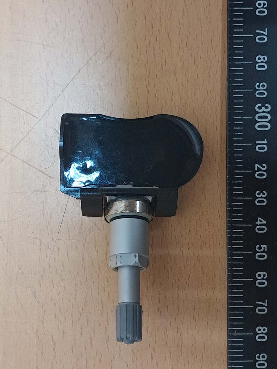
External Photos
Report No.: T100609402 Date of Issue: September 30, 2010 Page 1 Total Page: 6 Rev. 00 PHOTOGRAPHS OF EUT External Photo Report No.: T100609402 Date of Issue: September 30, 2010 Page 2 Rev. 00 Report No.: T100609402 Date of Issue: September 30, 2010 Page 3 Rev. 00
Test Report
Compliance Certification Services Inc. Report No.: T100609402-RP1 FCC ID: XVBX1C01 Date of Issue: October 14, 2010 Note: This report shall not be reproduced except in full, without the written approval of Compliance Certification Services Inc. This document may be altered or revised by Compliance Certification Services Inc. personnel only, and shall be noted in the revision section of the document. Page 1 Total Page: 33 FCC 47 CFR PART 15 SUBPART C ANSI C63.4: 2003 TEST REPORT For TPM Sensor Model: BX1-017 Data Applies To : BX1-003; BX1-006; BX1-007; BX1-008; BX1-010 BX1-011; BX1-012; BX1-014; BX1-015; BX1-016 Trade Name: SMP Issued to Standard Motor Products, Inc. 37-18 Northern Boulevard, Long Island City, New York 11101 Issued by Compliance Certification Services Inc. Ta i n a n L a b . No. 8, Jiu Cheng Ling, Jiaokeng Village, Sinhua Township, Tainan Hsien 712, Taiwan R.O.C. TEL: (06) 580-2201 FAX: (06) 580-2202 Issued Date: September 30, 2010 Compliance Certification Services Inc. Report No.: T100609402-RP1 FCC ID: XVBX1C01 Date of Issue: October 14, 2010 Page 2 REVISION HISTORY Rev. Issue Date Revisions Effect Page Revised By 00 October 14, 2010 Initial Issue ALL Selena.Chong Compliance Certification Services Inc. Report No.: T100609402-RP1 FCC ID: XVBX1C01 Date of Issue: September 30, 2010 Page 3 TABLE OF CONTENTS 1. TEST RESULT CERTIFICATION............................................................................................. 4 2. EUT DESCRIPTION .................................................................................................................... 5 3. TEST METHODOLOGY ............................................................................................................. 6 3.1 EUT CONFIGURATION.............................................................................................................. 6 3.2 EUT EXERCISE......................................................................................................................... 6 3.3 GENERAL TEST PROCEDURES.................................................................................................. 6 3.4 FCC PART 15.205 RESTRICTED BANDS OF OPERATIONS .............................................. 7 3.5 DESCRIPTION OF TEST MODES................................................................................................. 7 4. INSTRUMENT CALIBRATION................................................................................................. 8 4.1 MEASURING INSTRUMENT CALIBRATION........................................................................... 8 4.2 MEASUREMENT EQUIPMENT USED .............................................................................. 8 5. FACILITIES AND ACCREDITATIONS ................................................................................... 9 5.1 FACILITIES.............................................................................................................................. 9 5.2 EQUIPMENT............................................................................................................................. 9 5.3 LABORATORY ACCREDITATIONS AND LISTING....................................................................... 9 5.4 TABLE OF ACCREDITATIONS AND LISTINGS.......................................................................... 10 6. SETUP OF EQUIPMENT UNDER TEST ................................................................................ 11 6.1 SETUP CONFIGURATION OF EUT............................................................................................ 11 6.2 SUPPORT EQUIPMENT............................................................................................................ 11 7. FCC PART 15.231(E) REQUIREMENTS ................................................................................ 12 7.1 20 DB BANDWIDTH .......................................................................................................... 12 7.2 LIMIT OF TRANSMISSION TIME.............................................................................................. 14 7.3 DUTY CYCLE ..................................................................................................................... 16 7.4 RADIATED EMISSIONS........................................................................................................... 18 7.5 POWERLINE CONDUCTED EMISSIONS.................................................................................... 28 Compliance Certification Services Inc. Report No.: T100609402-RP1 FCC ID: XVBX1C01 Date of Issue: October 14, 2010 Page 4 1. TEST RESULT CERTIFICATION Product: TPM Sensor Model: BX1-017 Data Applies To: BX1-003; BX1-006; BX1-007; BX1-008; BX1-010 BX1-011; BX1-012; BX1-014; BX1-015; BX1-016 Brand Name: SMP Applicant: Standard Motor Products, Inc. 37-18 Northern Boulevard, Long Island City, New York 11101 Manufacturer: Orange Electronic Co., Ltd. No 15, Lane 81, Sec 2, Tanfu Rd., Tanzih, Taichung, Taiwan Tested: August 4, 2010 – October 13, 2010 APPLICABLE STANDARDS STANDARD TEST RESULT FCC 47 CFR Part 15 Subpart C ANSI C63.4 : 2003 No non-compliance noted We hereby certify that: The above equipment was tested by Compliance Certification Services Inc. The test data, data evaluation, test procedures, and equipment configurations shown in this report were made in accordance with the procedures given in ANSI C63.4: 2003 and the energy emitted by the sample EUT tested as described in this report is in compliance with conducted and radiated emission limits of FCC Rules Part 15.207, 15.209 and Part 15.231(a). The test results of this report relate only to the tested sample identified in this report. Approved by: Reviewed by: Jeter Wu Assistant Manager Eric Huang Assistant Section Manager Compliance Certification Services Inc. Report No.: T100609402-RP1 FCC ID: XVBX1C01 Date of Issue: September 30, 2010 Page 5 2. EUT DESCRIPTION Product TPM Sensor Model Number BX1-017 Data Applies To BX1…
Text truncated - open the document above for the full version.
Test Setup Photos
Compliance Certification Services Inc. Report No.: T100609402-RP1 FCC ID: XVBX1C01 Date of Issue: October 14, 2010 Note: This report shall not be reproduced except in full, without the written approval of Compliance Certification Services Inc. This document may be altered or revised by Compliance Certification Services Inc. personnel only, and shall be noted in the revision section of the document. Page 1 Total Page: 33 FCC 47 CFR PART 15 SUBPART C ANSI C63.4: 2003 TEST REPORT For TPM Sensor Model: BX1-017 Data Applies To : BX1-003; BX1-006; BX1-007; BX1-008; BX1-010 BX1-011; BX1-012; BX1-014; BX1-015; BX1-016 Trade Name: SMP Issued to Standard Motor Products, Inc. 37-18 Northern Boulevard, Long Island City, New York 11101 Issued by Compliance Certification Services Inc. Ta i n a n L a b . No. 8, Jiu Cheng Ling, Jiaokeng Village, Sinhua Township, Tainan Hsien 712, Taiwan R.O.C. TEL: (06) 580-2201 FAX: (06) 580-2202 Issued Date: September 30, 2010 Compliance Certification Services Inc. Report No.: T100609402-RP1 FCC ID: XVBX1C01 Date of Issue: October 14, 2010 Page 2 REVISION HISTORY Rev. Issue Date Revisions Effect Page Revised By 00 October 14, 2010 Initial Issue ALL Selena.Chong Compliance Certification Services Inc. Report No.: T100609402-RP1 FCC ID: XVBX1C01 Date of Issue: September 30, 2010 Page 3 TABLE OF CONTENTS 1. TEST RESULT CERTIFICATION............................................................................................. 4 2. EUT DESCRIPTION .................................................................................................................... 5 3. TEST METHODOLOGY ............................................................................................................. 6 3.1 EUT CONFIGURATION.............................................................................................................. 6 3.2 EUT EXERCISE......................................................................................................................... 6 3.3 GENERAL TEST PROCEDURES.................................................................................................. 6 3.4 FCC PART 15.205 RESTRICTED BANDS OF OPERATIONS .............................................. 7 3.5 DESCRIPTION OF TEST MODES................................................................................................. 7 4. INSTRUMENT CALIBRATION................................................................................................. 8 4.1 MEASURING INSTRUMENT CALIBRATION........................................................................... 8 4.2 MEASUREMENT EQUIPMENT USED .............................................................................. 8 5. FACILITIES AND ACCREDITATIONS ................................................................................... 9 5.1 FACILITIES.............................................................................................................................. 9 5.2 EQUIPMENT............................................................................................................................. 9 5.3 LABORATORY ACCREDITATIONS AND LISTING....................................................................... 9 5.4 TABLE OF ACCREDITATIONS AND LISTINGS.......................................................................... 10 6. SETUP OF EQUIPMENT UNDER TEST ................................................................................ 11 6.1 SETUP CONFIGURATION OF EUT............................................................................................ 11 6.2 SUPPORT EQUIPMENT............................................................................................................ 11 7. FCC PART 15.231(E) REQUIREMENTS ................................................................................ 12 7.1 20 DB BANDWIDTH .......................................................................................................... 12 7.2 LIMIT OF TRANSMISSION TIME.............................................................................................. 14 7.3 DUTY CYCLE ..................................................................................................................... 16 7.4 RADIATED EMISSIONS........................................................................................................... 18 7.5 POWERLINE CONDUCTED EMISSIONS.................................................................................... 28 Compliance Certification Services Inc. Report No.: T100609402-RP1 FCC ID: XVBX1C01 Date of Issue: October 14, 2010 Page 4 1. TEST RESULT CERTIFICATION Product: TPM Sensor Model: BX1-017 Data Applies To: BX1-003; BX1-006; BX1-007; BX1-008; BX1-010 BX1-011; BX1-012; BX1-014; BX1-015; BX1-016 Brand Name: SMP Applicant: Standard Motor Products, Inc. 37-18 Northern Boulevard, Long Island City, New York 11101 Manufacturer: Orange Electronic Co., Ltd. No 15, Lane 81, Sec 2, Tanfu Rd., Tanzih, Taichung, Taiwan Tested: August 4, 2010 – October 13, 2010 APPLICABLE STANDARDS STANDARD TEST RESULT FCC 47 CFR Part 15 Subpart C ANSI C63.4 : 2003 No non-compliance noted We hereby certify that: The above equipment was tested by Compliance Certification Services Inc. The test data, data evaluation, test procedures, and equipment configurations shown in this report were made in accordance with the procedures given in ANSI C63.4: 2003 and the energy emitted by the sample EUT tested as described in this report is in compliance with conducted and radiated emission limits of FCC Rules Part 15.207, 15.209 and Part 15.231(a). The test results of this report relate only to the tested sample identified in this report. Approved by: Reviewed by: Jeter Wu Assistant Manager Eric Huang Assistant Section Manager Compliance Certification Services Inc. Report No.: T100609402-RP1 FCC ID: XVBX1C01 Date of Issue: September 30, 2010 Page 5 2. EUT DESCRIPTION Product TPM Sensor Model Number BX1-017 Data Applies To BX1…
Text truncated - open the document above for the full version.
Contact Information
Applicant
John Gasiewski(Director of Engineering)
Test Firm
Compliance Certification Services Inc.Tommy WU
Technical Specifications
| # | Rule Parts | Frequency Range | Power Output |
|---|---|---|---|
| 1 | 15.231 | 315 MHz - 315 MHz | - |
Other Applications from Standard Motor Products, Inc.
XVBM2F03
Sep 26, 2022433MHz TPMS
Equipment Class
DSC - Part 15 Security/Remote Control Transmitter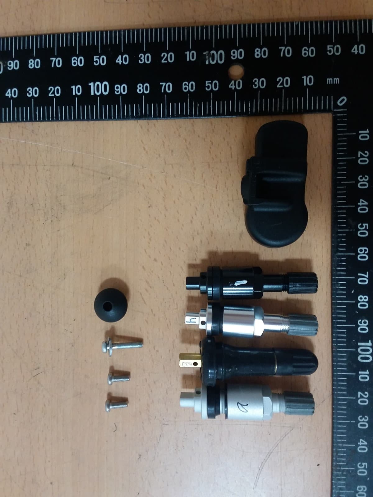
XVBU1FC1
Jul 20, 2020TPMS
Equipment Class
DSC - Part 15 Security/Remote Control Transmitter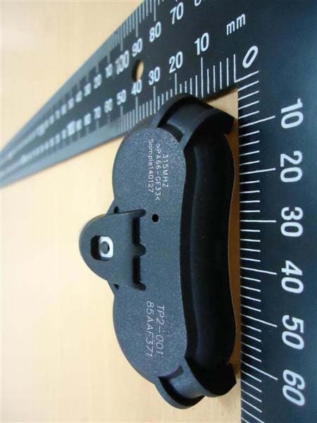
XVBW2C01
Oct 01, 2014TPMS
Equipment Class
DSC - Part 15 Security/Remote Control Transmitter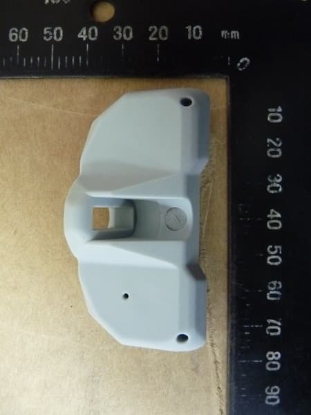
XVBB1B01
Oct 28, 2013TPMS
Equipment Class
DSC - Part 15 Security/Remote Control Transmitter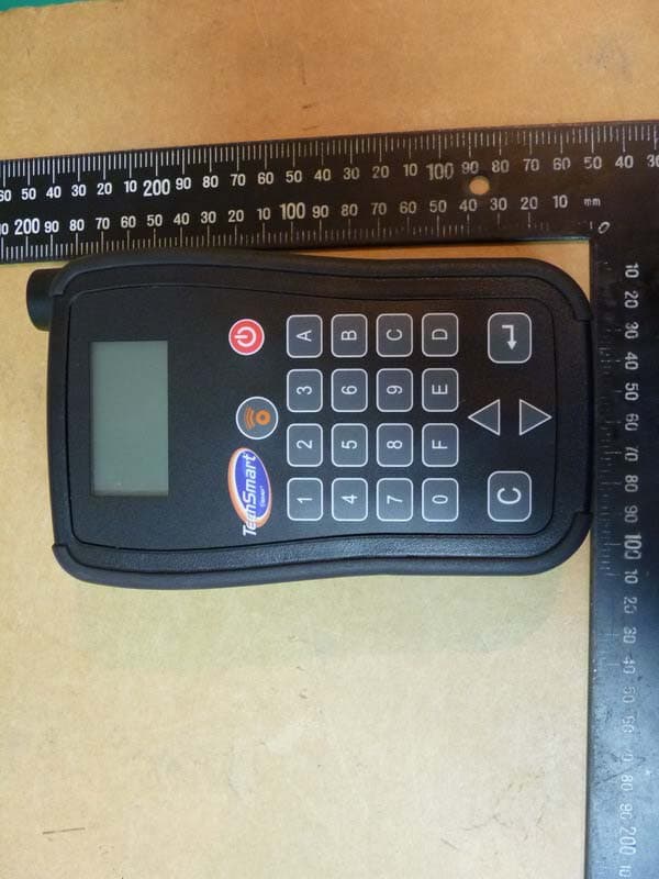
XVBPR2001
Sep 22, 2013TPM sensor tester
Equipment Class
DCD - Part 15 Low Power Transmitter Below 1705 kHz