FCCID.CO- FCC ID Database
HomeCompaniesEquipment ClassesSearch

© 2026 FCC ID Database. All rights reserved.

AboutContactData sourced from FCC public records
  1. Home/
  2. Espro Acoustiguide Group/
  3. XVIESLA2200

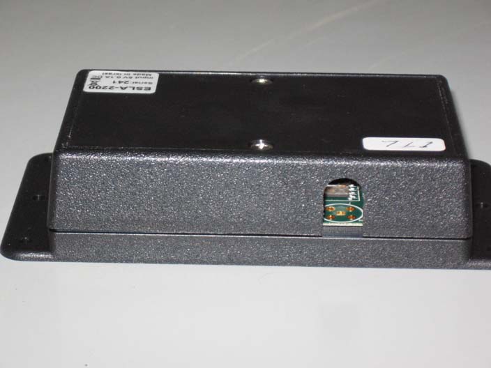
XVIESLA2200OPUS ACTIVATOR ANTI-THEFT ACTIVATOR

Espro Acoustiguide Group
OPUS ACTIVATOR ANTI-THEFT ACTIVATOR - FCC ID XVIESLA2200 - Espro Acoustiguide Group
Click to zoom

Application Details

Equipment Class
DXX - Part 15 Low Power Communication Device Transmitter
Date of Grant
Jan 23, 2011
Application Purpose
Original Equipment
Date of Application
Jan 19, 2011
Equipment Note
OPUS ACTIVATOR ANTI-THEFT ACTIVATOR
Frequency Range
2433.05000000 - 2433.05000000
Company
Espro Acoustiguide Group
Country
Israel

Documents & Files

Select a file to view

Users Manual

↗

Cover Letter(s)

↗
↗
↗

External Photos

↗

ID Label/Location Info

↗
↗

Internal Photos

↗

Operational Description

↗
↗

Test Report

↗

Test Setup Photos

↗

Document Text

Text extracted from the exhibit documents filed with the FCC. Open a document above to read the original.

Users Manual

O OO O O OO O p pp p p pp p u uu u u uu u s ss s s ss s A A u u t t o o   t t r r i i g g g g e e r r S S y y s s t t e e m m U U s s e e r r ' ' s s M M a a n n u u a a l l Opus System Opus OpusOpus Opus Autotrigger System User's Manual page 2 of 15 12 January, 2011 Table of Content Opus OpusOpus Opus....................................................................................................................... 1 1. Overview......................................................................................................... 3 2. Description ...................................................................................................... 5 2.1. Auto-trigger System Elements .......................................................................................................................... 5 2.2. Auto-trigger compatible Opus Player ............................................................................................................... 7 2.3. Opus Auto-trigger Activator ............................................................................................................................. 7 2.4. Functionality ..................................................................................................................................................... 8 3. Configuration ................................................................................................ 10 3.1. Activators........................................................................................................................................................ 10 3.2. Site requirements ............................................................................................................................................ 13 4. Installation..................................................................................................... 14 4.1. Installation Guidelines .................................................................................................................................... 14 Opus System Opus OpusOpus Opus Autotrigger System User's Manual page 3 of 15 12 January, 2011 1. Overview 1.1. The Opus system provides a Multimedia Guide for site visitors, incorporating in addition to the traditional high-quality audio playback multimedia content playback using its integral color screen. While the Opus Click provides a more “familiar” keypad interface, the Opus Touch model incorporates screen touch sensitivity input capability allowing for flexible user-interface schemes. The Opus portable Player can be used either with attached headphones connected to its built-in carrying strap, or using its built-in flipping speaker for flexibility and ease-of-use. 1.2. The Opus System incorporates a special feature to automatically trigger specific Content parts, by intercepting an “activation-zone” generated by pre-installed “Opus Auto-trigger Activator”. The Auto-trigger feature can activate: o Playback of a specific Item (of any type) o Playback of a specific Item synchronized to time-stamp supplied by external presentation control o Switch to a specific Tour (preserving the previous Language) This document instructs how to define and install a specific Auto-trigger system on site, including:  Auto-trigger system description & elements  Functionality  Specifications  Configuration options  Site requirements  Installation guidelines Opus System Opus OpusOpus Opus Autotrigger System User's Manual page 4 of 15 12 January, 2011 This device complies with Part 15 of the FCC Rules. Operation is subject to the following two conditions: (1) this device may not cause harmful interference, and (2) this device must accept any interference received, including interference that may cause undesired operation. FCC Warning Modifications not expressly approved by the manufacturer could void the user authority to operate the equipment under FCC Rules. Opus System Opus OpusOpus Opus Autotrigger System User's Manual page 5 of 15 12 January, 2011 2. Description 2.1. Auto-trigger System Elements 2.1.1. The Auto-trigger system of Opus is constructed of the following elements: 2.1.2.1. For the triggering locations – A dedicated Opus “Auto-trigger Activator” that creates an “Activation-zone” around it. This functionality is based upon specific RF technology. The Activator emits commands that specify which Item or Tour to activate, and adds the time-stamp for Synchronization. 2.1.2.2. For Synchronization – A dedicated “Time Code Reader” (“TCR”) that decodes the time-stamp signal supplied by the external presentation controller and sends it to the Activator. 2.1.2.3. Inside each Opus player: • An “Auto-trigger Sensor” that senses when the player has intercepted an Activation-zone. • Auto-trigger software in the Opus player that activates the Tour or Item upon interception, including the use of the time-stamp for Synchronization. 2.1.2. The following illustrates the system basic principles: Opus Player Content activated Activation-zone Activation Range Opus Autotrigger Activator Opus System Opus OpusOpus Opus Autotrigger System User's Manual page 6 of 15 12 January, 2011 2.1.3. The following shows the system block diagram: Powerin Opus Player Sensor Software Screen & Audio Autotrigger Activation signal Opus A Activator Internal Antenna Opus Activator Opus TCR Power supply Timecode signal supplied from external presentation control (for Synchronization only) Opus System Opus OpusOpus Opus Autotrigger System User's Manual page 7 of 15 12 January, 2011 2.2. Auto-trigger compatible Opus Player 2.2.1. The Auto-trigger ingredients in Opus player are internal and are not observed externally. 2.2.2. All Opus players contain as standard the appropriate hardware & software for Auto-trigger functionality. 2.3. Opus Auto-trigger Activator 2.3.1. The following shows the Opus Auto-trigger Activator: 2.3.2. Specifications: • Dimensions: 100 x 60 x 30 mm (excluding power-supply) • Weight: 105 g …

Text truncated - open the document above for the full version.

Cover Letter(s)

17 Atir Yeda St. | Kfar-Saba 44643, Israel | Tel: +972-9-7634400 | Fax: +972-9-7634411 | www.espro.com www.acoustiguide.com New York • Washington DC • London • Paris • Berlin • Amsterdam • Salzburg • Milan • Madrid • Prague • Porto • St. Petersburg • Tel Aviv • Istanbul • Mexico City • Rio de Janeiro • Taipei • Shanghai • New Delhi • Sydney 08 August, 2010 Letter of individual Authorization to sign Form 731 To: Timco Engineering Inc. To Whom It May Concern We hereby authorize Shaike Raz of ITL as an authorized individual to sign for form 731 in the favor of FCC ID: XVIESLA2200 application. Thank you,

Cover Letter(s)

17 Atir Yeda St. | Kfar-Saba 44643, Israel | Tel: +972-9-7634400 | Fax: +972-9-7634411 | www.espro.com www.acoustiguide.com New York • Washington DC • London • Paris • Berlin • Amsterdam • Salzburg • Milan • Madrid • Prague • Porto • St. Petersburg • Tel Aviv • Istanbul • Mexico City • Rio de Janeiro • Taipei • Shanghai • New Delhi • Sydney Federal Communications Commission Authorization and Evaluation Division Subject: Confidentiality Request regarding application for certification of FCC ID: XVIESLA2200 08 August, 2010 Dear Sirs Pursuant to Sections 0.457 and 0.459 of the Commission’s Rules, we hereby request confidential treatment of information accompanying this application as outlined below: CONF APPENDIX ESLA-2200 Schem.pdf (Schematics) CONF APPENDIX ESLA-2200 PartsLst.pdf (BOM, Parts List) CONF APPENDIX ESLA-2200 BlkDia.pdf (Block Diagram) The above materials contain trade secrets and proprietary information not customarily released to the public. The public disclosure of these materials may be harmful to the applicant and provide unjustified benefits to its competitors. The applicant understands that pursuant to Section 0.457 of the Rules, disclosure of this application and all accompanying documentation will not be made before the date of the Grant for this application. Sincerely,

Cover Letter(s)

17 Atir Yeda St. | Kfar-Saba 44643, Israel | Tel: +972-9-7634400 | Fax: +972-9-7634411 | www.espro.com www.acoustiguide.com New York • Washington DC • London • Paris • Berlin • Amsterdam • Salzburg • Milan • Madrid • Prague • Porto • St. Petersburg • Tel Aviv • Istanbul • Mexico City • Rio de Janeiro • Taipei • Shanghai • New Delhi • Sydney 8-Aug-10 To: Timco Engineering Inc. To Whom It May Concern We hereby authorize Shaike Raz of ITL to act on the behalf of Espro Ltd, regarding the FCC ID Certification process for the following applications Unit Name /Model: ESLA-2200 FCC ID: XVIESLA2200 Thank you,

ID Label/Location Info

Label Location

ID Label/Location Info

2200

Operational Description

Operation Description The Anti‐theft system of Opus is constructed of the following elements: • For the exit gates – A dedicated Opus “Anti‐theft Activator” that creates an “Activation‐zone” around it. This functionality is based upon specific RF technology. Inside each Opus player: • An “Anti‐theft Sensor” that senses when the player has intercepted an Activation‐ zone. • A buzzer to create the audible alarm sound. Anti‐theft software in the Opus player that invokes the Anti‐theft Alarm upon interception. The Activator is installed in the vicinity of the exit areas that need to be protected. It emits the Activation signal continuously upon connection to power‐line (after a ~10sec boot process). A green light indicator on the Activator box edge next to the power‐in connector designates it is ON, and a series of internal beeps designates “boot” termination and start of signal emission.

Test Report

Test Report E97952.01 Espro Information Technologies Ltd. Page 1 of 37 ITL FCCMASVE 1.25 26 March 2003 DATE: 27 December 2010 I.T.L. (PRODUCT TESTING) LTD. FCC Radio Test Report for Espro Information Technologies Ltd. Equipment under test: Anti-theft Activator* Opus Activator* *See customer declaration on page 4. Written by: _____________________________ E. Ever, Documentation Approved by: _____________________________ A. Sharabi, Test Engineer Approved by: _____________________________ I. Raz, EMC Laboratory Manager This report must not be reproduced, except in full, without the written permission of I.T.L. (Product Testing) Ltd. This report relates only to items tested. Test Report E97952.01 Espro Information Technologies Ltd. Page 2 of 37 ITL FCCMASVE 1.25 26 March 2003 Measurement/Technical Report for Espro Information Technologies Ltd. Equipment under test: Anti-theft Activator FCC ID: XVIESLA2200 This report concerns: Original Grant: x Class I change: Class II change: 47CFR15 Section 15.249 (a-b) Measurement procedure used is ANSI C63.4-2003. Application for Certification Applicant for this device: prepared by: (different from "prepared by") Ishaiahou Raz Eyal Ben Gigi ITL (Product Testing) Ltd. Espro Information Kfar Bin Nun Technologies Ltd. D.N. Shimshon 99780 17 Atir Yeda St., Kfar-Saba Israel 44643, Israel Tel: +972-8-915-3100 Tel: +972-09-763-4400 Fax: +972-8-915-3101 Fax: +972-09-763-4411 Email: [email protected] Email: [email protected] Test Report E97952.01 Espro Information Technologies Ltd. Page 3 of 37 ITL FCCMASVE 1.25 26 March 2003 TABLE OF CONTENTS 1. GENERAL INFORMATION ------------------------------------------------------------------------------- 4 1.1 Administrative Information ................................................................................. 4 1.2 List of Accreditations ......................................................................................... 5 1.3 Product Description ........................................................................................... 6 1.4 Test Methodology .............................................................................................. 6 1.5 Test Facility ....................................................................................................... 6 1.6 Measurement Uncertainty ................................................................................. 6 2. SYSTEM TEST CONFIGURATION --------------------------------------------------------------------- 7 2.1 Justification ........................................................................................................ 7 2.2 EUT Exercise Software ..................................................................................... 7 2.3 Special Accessories .......................................................................................... 7 2.4 Equipment Modifications ................................................................................... 7 2.5 Configuration of Tested System ........................................................................ 7 3. CONDUCTED EMISSION FROM AC MAINS -------------------------------------------------------- 8 3.1 Test Specification .............................................................................................. 8 3.2 Test Procedure .................................................................................................. 8 3.3 Test Results....................................................................................................... 8 3.4 Test Instrumentation Used, Conducted Measurement ................................... 13 4. AVERAGE FACTOR CALCULATION ----------------------------------------------------------------14 5. FIELD STRENGTH OF FUNDAMENTAL ------------------------------------------------------------16 5.1 Test Specification ............................................................................................ 16 5.2 Test Procedure ................................................................................................ 16 5.3 Measured Data ................................................................................................ 16 5.4 Test Instrumentation Used, Field Strength of Fundamental ........................... 20 6. SPURIOUS RADIATED EMISSION 9 KHZ - 1000 MHZ -----------------------------------------21 6.1 Test Specification ............................................................................................ 21 6.2 Test Procedure ................................................................................................ 21 6.3 Measured Data ................................................................................................ 21 6.4 Test Instrumentation Used .............................................................................. 22 6.5 Field Strength Calculation ............................................................................... 23 7. SPURIOUS RADIATED EMISSION 1.0 – 24.5 GHZ ----------------------------------------------24 7.1 Test Specification ............................................................................................ 24 7.2 Test Procedure ................................................................................................ 24 7.3 Test Data ......................................................................................................... 24 7.4 Test Instrumentation Used .............................................................................. 26 8. SET UP PHOTOGRAPH ---------------------------------------------------------------------------------27 9. APPENDIX A - CORRECTION FACTORS ----------------------------------------------------------28 9.1 Correction factors for CABLE ......................................................................... 28 9.2 Correction factors for CABLE ......................................................................... 29 9.3 Correction factors for CABLE ..................................…

Text truncated - open the document above for the full version.

Contact Information

Applicant

Eyal Ben Gigi(COO)
[email protected]97297634400Fax: 97297634411

Test Firm

Israel Testing LaboratoriesIIan Cohen
[email protected]972-3-5339022Fax: 972-3-5339019

Technical Specifications

#Rule PartsFrequency RangePower Output
115C2.43 GHz - 2.43 GHz-
Confidentiality
Long Term

Other Applications from Espro Acoustiguide Group
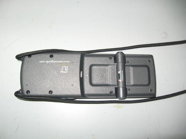
OPUS PLAYER:TOUCH; OPUS PLAYER:CLICK - FCC ID XVIESLP4X00 - Espro Acoustiguide Group
XVIESLP4X00

OPUS PLAYER:TOUCH; OPUS PLAYER:CLICK

Dec 29, 2009

Equipment Class

DXX - Part 15 Low Power Communication Device Transmitter