XWI200910BMEDIPENDANT (BASE STATION)
Wearable Health Solutions. Inc.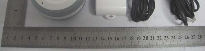
Click to zoom
Application Details
- Equipment Class
- PUB - Part 15 Unlicensed PCS Base Station
- Date of Grant
- Mar 02, 2010
- Application Purpose
- Original Equipment
- Date of Application
- Mar 01, 2010
- Equipment Note
- MEDIPENDANT (BASE STATION)
- Frequency Range
- 1921.53600000 - 1928.44800000
- Country
- United States
Documents & Files
Document Text
Text extracted from the exhibit documents filed with the FCC. Open a document above to read the original.
Users Manual
5215-C Militia Hill Road, Plymouth Meeting, PA 19462 www.MedicalAlarmConcepts.com TM Rev. Man01 08/09 MediPendant ™ Model #MED01 OWNER’S MANUAL Manufactured by TM Introduction to the MediPendant™ ................................................................... 2 Products Included In Your MediPendant™ Kit .................................................. 3 Product Features ........................................................................................... 4-5 Installing Your MediPendant™ ........................................................................ 6-9 Testing Your MediPendant™ For The First Time ........................................ 10-11 Operating Your MediPendant™ ................................................................... 12-13 Wearing Your MediPendant™........................................................................... 14 In An Emergency ........................................................................................... 15 Battery Test ..................................................................................................... 16 System/Range Test ......................................................................................... 17 Installing/Replacing the Battery ................................................................... 18 Troubleshooting ............................................................................................. 19 General Warnings .......................................................................................... 20 Safety Precautions ......................................................................................... 21 Limited Warranty and Disclaimer ............................................................ 22-24 TABLE OF CONTENTS OWNER’S MANUAL Model #MED01 MediPendant ™ Please read this manual completely and save it for future reference. 1 Customer Service Phone #: ________________________________ Thank you for choosing MediPendant™ - the ONLY medical alert device that allows you to speak and listen directly through the pendant. MediPendant™ was designed to give you the mobility and freedom to move in and around your home without worry. Each MediPendant™ has been carefully tested and inspected to meet the highest quality standards. Simply press the button on your pendant to be connected to an Emergency Medical Technician (EMT)-certified operator – 24 hours a day/7 days a week. The easy-to-use features include: • One-button activation – there is no keypad on the pendant or the base station so the unit can ONLY call the emergency call center. • Can be worn around the neck, clipped to your belt, or around your wrist. • Battery provides up to six hours of talk time and up to one year of stand- by time. • MediPendant™ is water-resistant. While pendant may be worn in the bath or shower, it should not be exposed to water for prolonged periods of time.** • Operates anywhere from 300 ft. to 600 ft. in and around your home.*† • Easy installation – plugs easily into any standard power outlet and telephone jack. INTRODUCTION TO THE MediPendant™ MediPendant ™ 2 *Line of sight. † Building structure and conditions may affect range. **Base station should never be exposed to water. SET UP SilentPOWER On = System in Use Blinking = Phone Line Trouble AC/DC Adapter (Power Cord) Pendant Base Station Wrist Strap OPTIONAL Arm Band 6 ft. Telephone Cord Break Away Neck Lanyard Belt Clip Screwdriver PRODUCTS INCLUDED IN YOUR MediPendant™ KIT OPTIONAL ACCESSORIES OWNER’S MANUAL Model #MED01 3 Lithium Photo Battery 123 (1 Installed, 1 Extra Included) BATTERY Spare Screws and O-Rings OPTIONAL Lock Box OPTIONAL DSL Filter D S L F I L T E R PRODUCT FEATURES PENDANT MediPendant ™ Large, easy-to-find emergency button Protective rubber edge Water-resistant Two-way audio speaker Battery/System Test button Ergonomically designed Range indicator light Battery indicator light Water drainage port Full duplex mic 4 SET UP SilentPOWER On = System in Use Blinking = Phone Line Trouble BASE STATION OWNER’S MANUAL Model #MED01 Easy to see indicator lights Small size fits almost anywhere Speaker for alert and warning tones Rubber base won’t scratch furniture Cradle for resting pendant Easy to see color-coded jacks Back up battery located inside 5 MediPendant ™ 6 Your MediPendant™ will operate using your existing telephone line and service. No special features or services are required. STEP 1 Place the MediPendant™ base station on a stable surface located near a power outlet and an available phone jack. For best results, locate the base station in an area away from household appliances which could present electrical interference. See Figure 6A If you are using more than one MediPendant™ system in your home, we recommend that you place the base stations at least 15 ft. apart from each other. STEP 2 Grab RED TAB located on side of base station and pull it straight out. Removing tab activates back-up battery. See Figure 6B Unit will beep continuously and the POWER LED and PHONE LINE INDICATOR LED will both flash RED until AC/DC adapter is plugged in. See STEP 3. INSTALLING YOUR MediPendant™ Figure 6A Figure 6B Phone JackPower Outlet STEP 3 Connect the AC/DC Adapter into the BLACK plug in the back of the base station marked DC. See Figure 7A STEP 4 Connect the other end of the AC/DC Adapter into a standard power outlet. See Figure 7B Once plugged in, your base unit will continue to beep and the RED PHONE LINE INDICATOR LED will continue to flash. The POWER LED will change from flashing RED to solid GREEN. NOTE: DO NOT PLUG THE AC/DC ADAPTER INTO A POWER OUTLET WHICH IS CONTROLLED BY A WALL SWITCH. If the switch is accidently turned off, the system will begin to beep indicating a loss of power. NOTE: With loss of power, the POWER LED located in the center on the top of the base station will illuminate and flash RED and the unit will beep. OWNER’S MANUAL Model #MED01 7 DCEXTRA PHONE JACK PHONE LINE IN FROM WALL OUTLET DCEX…
Text truncated - open the document above for the full version.
Cover Letter(s)
Medical Alarm Concepts 5215-C Militia Hill Road, Plymouth Meeting, PA 19462 (Pennsylvania) Federal Communications Commission Authorization and Evaluation Division Confidentiality Request regarding application for certification of FCC ID: XWI200910B Pursuant to Sections 0.457 and 0.459 of the Commission’s Rules, we hereby request confidential treatment of information accompanying this application as outlined below: Exhibit Type File Name Schematics CONF_XWI200910B_FCC_Schematics.pdf Block Diagram CONF_XWI200910B_FCC_BlockDiagram.pdf Operational Description CONF_XWI200910B_FCC_OperationalDescription.pdf The above materials contain trade secrets and proprietary information not customarily released to the public. The public disclosure of these materials may be harmful to the applicant and provide unjustified benefits to its competitors. The applicant understands that pursuant to Section 0.457 of the Rules, disclosure of this application and all accompanying documentation will not be made before the date of the Grant for this application. Sincerely, Medical Alarm Concepts - - - - - - - - - - - - - - - - - - - - (Howard Teicher/ Executive Officer)
External Photos
Medical Alarm Concepts Model: MED01 REPORT NO.: STR09108104I-1 FCC PART 15D EXHIBIT 2 - EUT EXTERNAL PHOTOGRAPHS EUT View 1 EUT View 2 (Base Station Uint) Medical Alarm Concepts Model: MED01 REPORT NO.: STR09108104I-1 FCC PART 15D EUT View 3 (Base Station Uint)
ID Label/Location Info
Medical Alarm Concepts Model: MED01 REPORT NO.: STR09108104I-1 FCC PART 15D EXHIBIT 1- PRODUCT LABELING Proposed FCC ID Label Format Specifications : Text is Black in color and justified. Labels are printed in indelible ink on permanent adhesive silk-screened onto the EUT or shall be affixed at a conspicuous location on the EUT. Proposed Label Location on EUT FCC ID Label Location Base Station Unit
ID Label/Location Info
Medical Alarm Concepts Model: MED01 REPORT NO.: STR09108104I-1 FCC PART 15D EXHIBIT 1- PRODUCT LABELING Proposed FCC ID Label Format Specifications : Text is Black in color and justified. Labels are printed in indelible ink on permanent adhesive silk-screened onto the EUT or shall be affixed at a conspicuous location on the EUT. Proposed Label Location on EUT FCC ID Label Location Base Station Unit
Internal Photos
Medical Alarm Concepts Model: MED01 REPORT NO.: STR09108104I-1 FCC PART 15D EXHIBIT 3 - EUT INTERNAL PHOTOGRAPHS EUT Housing and Board View (Base Station Unit) Solder Board-Component View 1 (Base Station Unit) Medical Alarm Concepts Model: MED01 REPORT NO.: STR09108104I-1 FCC PART 15D Solder Board-Component View 2 (Base Station Unit)
RF Exposure Info
MAXIMUM PERMISSION EXPOSEURE Standard Applicable According to §1.1307(b)(1), system operating under the provisions of this section shall be operating in a manner that the public is not exposed to radio frequency energy level in excess limit for maximum permissible exposure. (a) Limits for Occupational / Controlled Exposure Frequency range (MHz) Electric Field Strength (E) (V/m) Magnetic Field Strength (H) (A/m) Power Density (S) (mW/cm 2 ) Averaging Times | E | 2 , | H | 2 or S (minutes) 0.3-3.0 614 1.63 (100)* 6 3.0-30 1842/f 4.89/f (900/f)* 6 30-300 61.4 0.163 1.0 6 300-1500 F/300 6 1500-100000 5 6 (b) Limits for General Population / Uncontrolled Exposure Frequency range (MHz) Electric Field Strength (E) (V/m) Magnetic Field Strength (H) (A/m) Power Density (S) (mW/cm 2 ) Averaging Times | E | 2 , | H | 2 or S (minutes) 0.3-1.34 614 1.63 (100)* 30 1.34-30 824/f 2.19/f (180/f)* 30 30-300 27.5 0.073 0.2 30 300-1500 F/1500 30 1500-100000 1 30 Note: f = frequency in MHz: * = Plane-wave equivalents power density MPE Calculation Method S =(P*G) / (4*∏*R 2 ) S = power density (in appropriate units, e.g., mw/cm 2 ) P = power input to the antenna (in appropriate units, e.g., mw) G = power gain of the antenna in the direction of interest relative to an isotropic radiator, the power gain factor is normally numeric gain. R = distance to the center of radiation of the antenna (in appropriate units, e.g., cm) MPE Calculation Result For Base Station Unit Maximum peak output power at antenna input terminal: 18.55(dBm) Maximum peak output power at antenna input terminal: 71.61434(mW) Prediction distance: 20 (cm) Prediction frequency: 1928.448 (MHz) Antenna gain (typical): 0 (dBi) Antenna gain (numeric): 1 (numeric) The worst case is power density at prediction frequency at 20cm: 0.014247 (mw/cm 2 ) MPE limit for general population exposure at prediction frequency: 1 (mw/cm 2 ) 0.014247 (mw/cm 2 ) < 1 (mw/cm 2 ) Result: Compliant
Test Report
Medical Alarm Concepts Model: MED01 REPORT NO.: STR09108104I-1 PAGE 1 OF 38 FCC PART 15D FCC Part 15D Measurement and Test Report For Medical Alarm Concepts 5215-C Militia Hill Road, Plymouth Meeting, PA 19462(Pennsylvania) FCC ID: XWI200910B Report Concerns: Original Report Equipment Type: MediPendant (Base Station) Model: MED01 Report No.: STR09108104I-1 Test/Witness Engineer: Test Date: 2009-10-30 to 2009-11-10 Issue Date: 2009-11-17 Prepared By: SEM.Test Compliance Service Co., Ltd 3/F, Jinbao Commerce Building, Xin'an Fanshen Road, Bao'an District, Shenzhen, P.R.C.(518101) Approved & Authorized By: Jandy So / PSQ Manager Note: This test report is limited to the above client company and the product model only. It may not be duplicated without prior permitted by SEM.Test Compliance Service Co., Ltd . Medical Alarm Concepts Model: MED01 REPORT NO.: STR09108104I-1 PAGE 2 OF 38 FCC PART 15D TABLE OF CONTENTS 1. GENERAL INFORMATION ...................................................................................................................................4 1.1 PRODUCT DESCRIPTION FOR EQUIPMENT UNDER TEST (EUT)...............................................................................4 1.2 TEST STANDARDS...................................................................................................................................................4 1.3 RELATED SUBMITTAL(S)/GRANT(S) .......................................................................................................................4 1.4 TEST METHODOLOGY.............................................................................................................................................5 1.5 TEST FACILITY.......................................................................................................................................................5 1.6 EUT EXERCISE SOFTWARE....................................................................................................................................5 1.7 ACCESSORIES EQUIPMENT LIST AND DETAILS.......................................................................................................5 1.8 EUT CABLE LIST AND DETAILS.............................................................................................................................5 2. SUMMARY OF TEST RESULTS ...........................................................................................................................6 3. RF RADIATION EXPOSEURE ..............................................................................................................................7 3.1 STANDARD APPLICABLE.........................................................................................................................................7 3.2 MPE CALCULATION METHOD................................................................................................................................7 3.3 MPE CALCULATION RESULT..................................................................................................................................8 4. ANTENNA REQUIREMENT ..................................................................................................................................9 4.1 STANDARD APPLICABLE.........................................................................................................................................9 4.2 TEST RESULT..........................................................................................................................................................9 5. CONDUCTED EMISSIONS ..................................................................................................................................10 5.1 MEASUREMENT UNCERTAINTY............................................................................................................................10 5.2 TEST EQUIPMENT LIST AND DETAILS...................................................................................................................10 5.3 TEST PROCEDURE.................................................................................................................................................10 5.4 BASIC TEST SETUP BLOCK DIAGRAM...................................................................................................................10 5.5 ENVIRONMENTAL CONDITIONS............................................................................................................................11 5.6 SUMMARY OF TEST RESULTS/PLOTS....................................................................................................................11 5.7 CONDUCTED EMISSIONS TEST DATA....................................................................................................................11 6. EMISSION BANDWIDTH .....................................................................................................................................14 6.1 STANDARD APPLICABLE.......................................................................................................................................14 6.2 TEST EQUIPMENT LIST AND DETAILS...................................................................................................................14 6.3 TEST PROCEDURE.................................................................................................................................................14 6.4 ENVIRONMENTAL CONDITIONS............................................................................................................................14 6.5 SUMMARY OF TEST RESULTS/PLOTS....................................................................................................................14 7. PEAK TRANSMIT POWER..................................................................................................................................16 7.1 STANDARD APPLICABLE....................................…
Text truncated - open the document above for the full version.
Test Setup Photos
Medical Alarm Concepts Model: MED01 REPORT NO.: STR09108104I-1 FCC PART 15D EXHIBIT 4 - TEST SETUP PHOTOGRAPHS Conducted Emission Test Setup (150kHz to 30MHz) Radiation Emission Test Setup (30MHz to 1GHz) Base Station Unit Medical Alarm Concepts Model: MED01 REPORT NO.: STR09108104I-1 FCC PART 15D Radiation Emission Test Setup (Above 1GHz) Base Station Uint Extreme Condition Test Setup Base Station Unit
Contact Information
Applicant
Peter Pezzino(President)
Test Firm
SEM.Test Compliance Service Co., Ltd.Jandy So
Technical Specifications
| # | Rule Parts | Frequency Range | Power Output |
|---|---|---|---|
| 1 | 15D | 1.92 GHz - 1.93 GHz | 72.00 mW |
Other Applications from Wearable Health Solutions. Inc.

XWI-EC4WHS
Jul 27, 2023iHelp Max 4G mobile medical device
Equipment Class
DSS - Part 15 Spread Spectrum Transmitter
XWI-CS2992014
Nov 15, 2014iHelp
Equipment Class
PCT - PCS Licensed Transmitter worn on body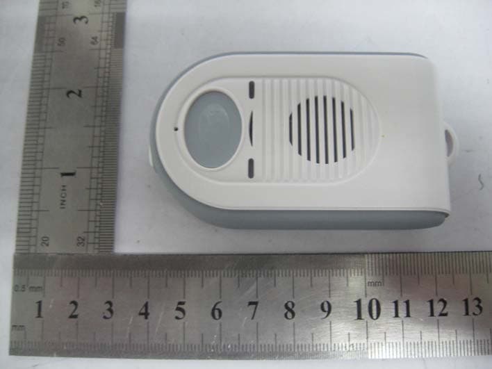
XWI200910P
Mar 07, 2010MEDIPENDANT
Equipment Class
PUF - Part 15 Unlicensed PCS portable Tx held to face