XWK8601015Dose Aware PDM
Unfors RaySafe AB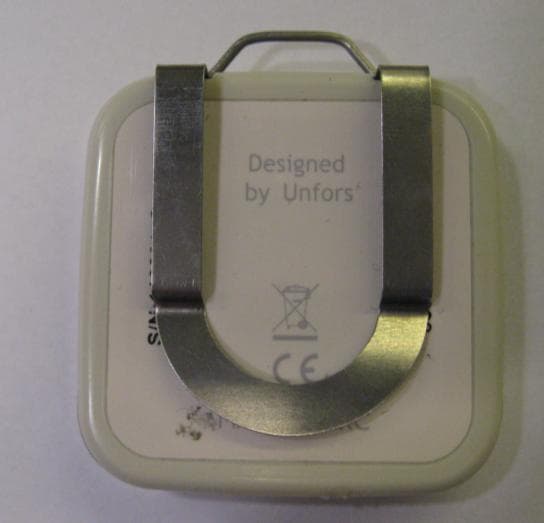
Click to zoom
Application Details
- Equipment Class
- DXX - Part 15 Low Power Communication Device Transmitter
- Date of Grant
- Jan 17, 2010
- Application Purpose
- Original Equipment
- Date of Application
- Jan 17, 2010
- Equipment Note
- Dose Aware PDM
- Frequency Range
- 918.30000000 - 918.30000000
- Company
- Unfors RaySafe AB
- Country
- Sweden
Documents & Files
Document Text
Text extracted from the exhibit documents filed with the FCC. Open a document above to read the original.
Users Manual
DoseAware Base Station Package Instructions for Use 2 Document version 1.0 DoseAware Base Station Package Philips Healthcare 9896 002 16621 Table of Contents 1 Introduction....................................................................................4 1.1 Intended Use of the DoseAware System...................................................4 1.2 About the DoseAware System...................................................................5 1.3 About this User Manual.............................................................................6 1.4 Other User Manuals...................................................................................6 1.5 System Requirements................................................................................6 2 Base Station Package Installation...................................................7 3 Use the Base Station.......................................................................8 3.1 Introduction...............................................................................................8 3.2 Getting Started..........................................................................................8 3.2.1 Wall Mounted Base Station....................................................................................8 3.2.2 MCS Mounted Base Station....................................................................................8 3.2.3 Troubleshooting......................................................................................................8 3.3 Base Station Features................................................................................9 3.3.1 Online View – View Current Dose Rates...............................................................10 3.3.2 Walk‐Up View – View Detailed Dose Data............................................................12 3.3.3 Base Station Settings View....................................................................................16 3.4 Shut Down the Base Station....................................................................20 4 Use DoseView...............................................................................21 4.1 Introduction to DoseView........................................................................21 4.2 Getting Started with DoseView...............................................................22 4.2.1 Troubleshooting....................................................................................................22 4.3 Home Toolbar Overview..........................................................................23 4.4 PDM Panel...............................................................................................24 4.4.1 PDM Information..................................................................................................24 4.4.2 Dose Information..................................................................................................25 4.4.3 Selection Summary...............................................................................................25 4.4.4 Change PDM Options............................................................................................25 4.5 View Dose Graph.....................................................................................27 4.6 View Dose Table......................................................................................28 4.7 Specify Password and Language..............................................................29 5 PDM..............................................................................................30 5.1 Introduction.............................................................................................30 5.2 Getting Started........................................................................................30 6 Cradle............................................................................................31 6.1 Introduction.............................................................................................31 6.2 Getting Started........................................................................................31 6.3 Troubleshooting.......................................................................................31 7 Maintenance.................................................................................32 7.1 Calibrating the Base Station Screen.........................................................32 7.2 Cleaning the Base Station Package Components.....................................32 7.3 Disinfection..............................................................................................32 8 Product Disposal...........................................................................33 DoseAware Base Station Package Document version 1.0 3 Philips Healthcare 9896 002 16621 9 Technical Data...............................................................................34 9.1 PDM Radiology........................................................................................34 9.2 PDM Memory..........................................................................................34 9.3 Base Station Memory..............................................................................34 9.4 Dose Data Transfer from PDM to Base Station........................................35 9.5 PDM and Base Station/DoseView Memories..........................................35 9.6 Time Management..................................................................................36 9.7 Technical Specifications...........................................................................36 9.7.1 Radio Communication...........................................................................................36 9.7.2 Base Station..........................................................................................................36 9.7.3 PDM..............................................................................................…
Text truncated - open the document above for the full version.
ID Label/Location Info
Date of Mfg: 01/2010 S/N: 0000 0000 9897 100 02291 P e rs o n a l D o s e M e te r 918,3 MHz SHIF T Design & Strategy AB, www .shiftdesign.se, 2009-08-31 SURFACE color Othe r Mushroom 40383 ? ? Thickness = Total 0.07-0.08mm Mater ial = Brady B-423 Tempeature range = -40°C to +100°C Prin ting must be with non-conductive color. Ser ial number font = Arial Narrow gloss texture Matt - C1 G1G2 G3G4 coating - 3050062 - Dose Aware PDM back panel 918 - Rev D Design Specification GRAPHICS color method ? ??? ? ? ? C2 ? ? C3 Unfors, Sweden C1 G1 10713 Dark Grey ? FCC ID: XWK8601015 MADE IN PRC Manufactured and Designed by Unfors Manufactured for PMS Nederland B.V.
Test Report
Date Reference Page REPORT FCC ID: XWK8601015 2009-11-17 F905629-F15C1 1 (2) Appendix 1 Performance test and requirements The tests were performed to verify that the electromagnetic compatibility of Unfors Alert Dosimeter (PDM, Personal DosiMeter) meets the requirements of FCC 47 CFR part 15 C. Test facility The used test site (SP 504 114) is compliant with the requirements of section 2.948 of the FCC rules and listed, registration number 96866, as a facility accepted for certification under parts 15 and 18. The site complies with RSS-Gen, Issue 2 and is accepted by Industry Canada for the performance of radiated measurements, file number: IC 3482A-2. Test object Transceiver: Unfors Alert Dosimeter Antenna: Integral, AMD1103-ST01 Antenna gain, peak: -0.5 dBd Antenna gain, average: -4.0 dBd Frequency: 918.3 MHz Frequency used during test: 918.3 MHz Modulation: GFSK Data rate: 125 kbps Supply voltage: 3.0 V DC, internal battery Lithium Operational test mode To simplify the measurements a modified test sample was used to be able to transmit continuous with modulation. The EUT was tested stand alone. The test was performed with continuous transmission (100% duty cycle) and with normal modulation. The EUT was set in desired mode with a PC via the s/w Terminal.exe v1.9b 20041226 with the EUT in the Unfors Alert Cradle. The used commando was: rtest 2: Transmit random modulated carrier Date Reference Page REPORT FCC ID: XWK8601015 2009-11-17 F905629-F15C1 2 (2) Appendix 1 Uncertainties Measurement and test instrument uncertainties are described in the quality assurance documentation ”EL-QD 8.2”. The measurement uncertainties can be found in the table below. The uncertainties are calculated with a coverage factor k=2 (95% level of confidence). The measurement uncertainties can be found in the table below: Method Uncertainty Radiated emission, 30 – 1000 MHz 4.8/5.6 dB (V/H-pol) Radiated emission, 1 – 40 GHz 2.6 dB Conducted emission 3.5 dB Reservation The test results in this report apply only to the particular test object as declared in the report. Delivery of test object The test object was delivered: 2009-09-14 Test engineer Fredrik Isaksson Date Reference Page REPORT FCC ID: XWK8601015 2009-11-17 F905629-F15C1 1 (2) Rev.1: 2009-12-28 Appendix 2 Field strength of fundamental measurements according to FCC 47 CFR part 15.249 (a) Date 2009-09-14 Temperature 23 °C ± 3 °C Humidity 41 % ± 5 % Test set-up and procedure The measurements were performed according to ANSI C63.4-2003. The radiated maximum peak radiated output power measurements were performed in the semi- anechoic chamber. The test was also performed with rotation of the EUT through three orthogonal axes to determine the position that produces the highest emission relative to the limit. The fundamental was scanned with PEAK-detector with the antenna height 1-4 m and the turntable was varied between 0-360 degrees for maximum response. The antenna distance during the measurements was 3.0 m. Final measurement was performed with detector according to the FCC rules. Test set-up photos during the tests can be found in appendix 8. Measurement equipment Calibration Due SP number Semi anechoic chamber, Edison 2010-01 504 114 Spectrum analyzer R&S ESI 26 2010-07 503 885 EMI measurement computer - - Software: R&S EMC32, ver. 6.30.10 - 503 745 Antenna Schaffner Bilog CBL6143 2010-03 504 079 Temperature and humidity meter Testo 625 2010-04 504 117 Date Reference Page REPORT FCC ID: XWK8601015 2009-11-17 F905629-F15C1 2 (2) Rev.1: 2009-12-28 Appendix 2 Results RBW=120 kHz Max peak output power Quasi-peak detector 918.3 MHz 918.3 MHz 918.3 MHz EUT axes X-axes Y-axes Z-axes Antenna height 1.00 m 1.00 1.33 m Azimuth 0 deg 14 deg 25 deg Polarization Horizontal Horizontal Vertical T nom 23°C V nom 3.0 V DC 88.0 dBμV/m (=-7.2 dBm ERP) Note 1 89.2 dBμV/m (=-6.0 dBm ERP) Note 1 83.6 dBμV/m (=-11.6 dBm ERP) Note 1 Note 1: The measurements were performed in field strength in dBμV/m. The ERP level was then calculated by the formula ERP = E(dBμV/m)-90+20log(d)-10log30 Note 2: According 47CFR 15.31(e), For intentional radiators, measurements of the variation of the input power or the radiated signal level of the fundamental frequency component of the emission, as appropriate, shall be performed with the supply voltage varied between 85% and 115% of the nominal rated supply voltage. For battery operated equipment, the equipment tests shall be performed using a new battery. Limits According to 47CFR 15.249(a), The field strength of emissions from intentional radiators operated within these frequency bands shall comply with the following: Fundamental Field strength of Field strength of Frequency fundamental harmonics 902-928 MHz 50 mV/m = 94 dBμV/m 500 μV/m = 54 dBμV/m Complies? Yes Date Reference Page REPORT FCC ID: XWK8601015 2009-11-17 F905629-F15C1 1 (2) Rev.1: 2009-12-28 Appendix 3 Radiated emission measurements according to FCC 47 CFR part 15.249 (d) (e) Date 2009-09-14 2009-09-15 2009-09-16 Temperature 23 °C ± 3 °C 23 °C ± 3 °C 23 °C ± 3 °C Humidity 41 % ± 5 % 33 % ± 5 % 40 % ± 5 % Test set-up and procedure The measurements were performed according to ANSI C63.4-2003. The test of radiated emission was performed in a semi anechoic chamber. The measurements were performed with both horizontal and vertical polarizations of the antenna. The antenna distance was 3 m. The test was also performed with rotation of the EUT through three orthogonal axes to determine the position that produces the highest emission relative to the limit. The measurement procedure is as the following: 1. A pre-measurement is performed with peak detector. The test object is measured in eight directions with the antenna at three heights, 1.0 m, 1.5 m and 2.0 m. 2. If the emission is close or above the limit during the pre-measurement, the test object is scanned 360 degrees and the antenna height scanned from 1 to 4 m for maximum response. Then the emission is measured with the quasi-peak detec…
Text truncated - open the document above for the full version.
Test Setup Photos
Date Reference Page REPORT FCC ID: XWK8601015 2009-11-17 F905629-F15C1 1 (6) Appendix 8 Photos The test set-up during all the radiated tests can be seen in the pictures below. Over-view, 0 degree at TT X-axis Date Reference Page REPORT FCC ID: XWK8601015 2009-11-17 F905629-F15C1 2 (6) Appendix 8 Y-axis Z-axis
Contact Information
Applicant
Jesper Bengtsson(Quality, Regulatory & Environmental Manager)
Technical Contact
Unfors Instruments ABMats Quick
[email protected]+46-31-719 97 18
Uggledalsv�gen 29 · Billdal · Sweden
Test Firm
SP Technical Research Institute of SwedenMagnus Winehem
Technical Specifications
| # | Rule Parts | Frequency Range | Power Output |
|---|---|---|---|
| 1 | 15C | 918.3 MHz - 918.3 MHz | - |
Other Applications from Unfors RaySafe AB
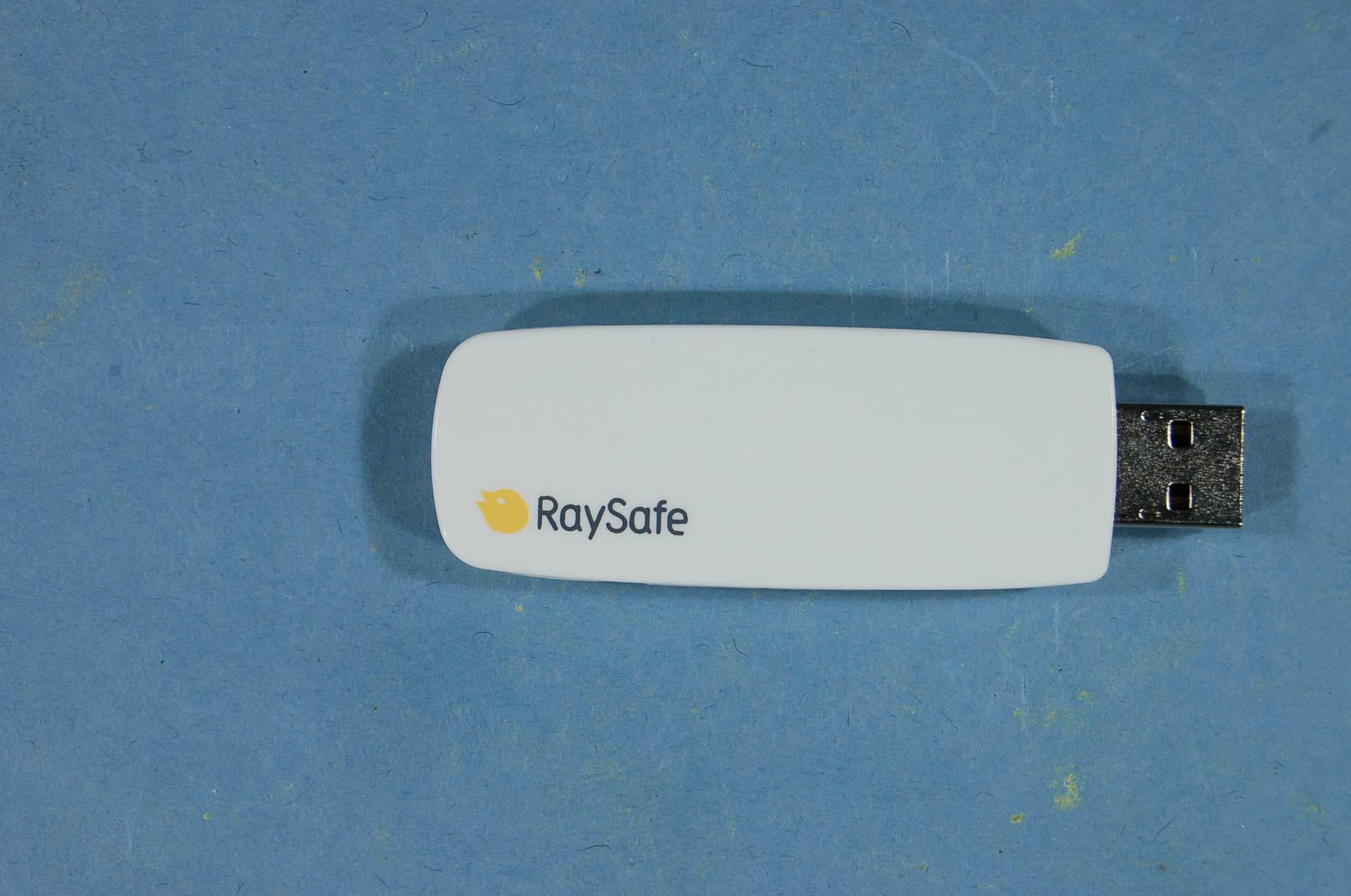
XWK8650202
Jan 09, 2013Dosimetry Radio (US)
Equipment Class
DXT - Part 15 Low Power Transceiver, Rx Verified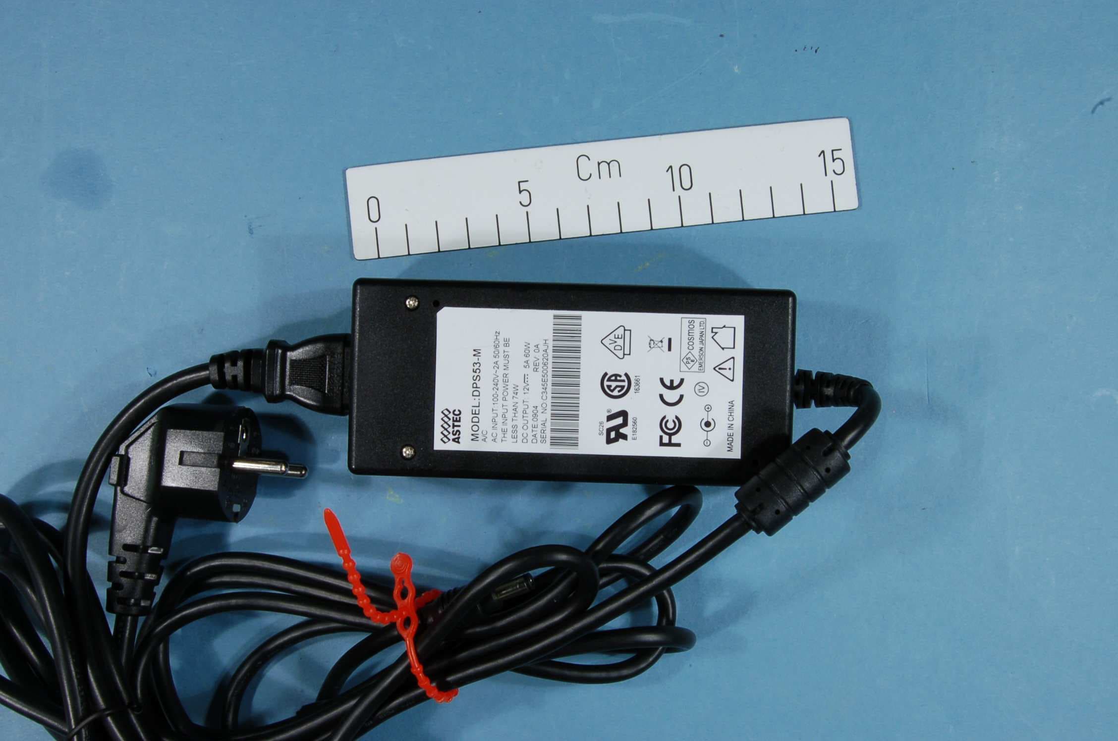
XWK8603022
Nov 10, 2011DoseAware Base Station
Equipment Class
DXT - Part 15 Low Power Transceiver, Rx Verified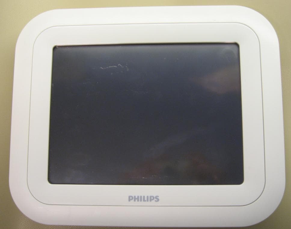
XWK8603021
Jan 17, 2010Dose Aware Base station
Equipment Class
DXX - Part 15 Low Power Communication Device Transmitter