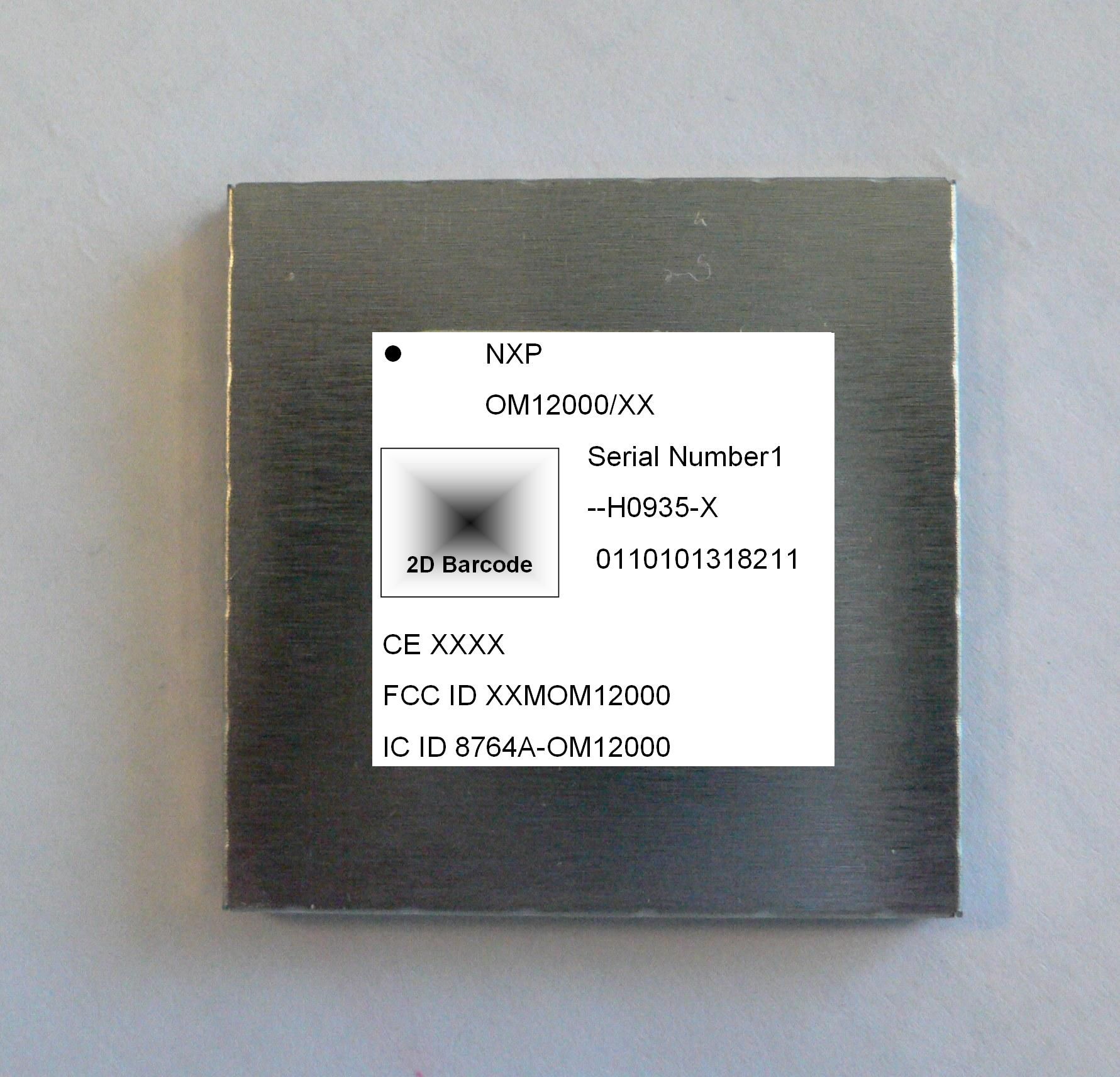
XXMOM12000GSM/GPRS Module
NXP Semiconductors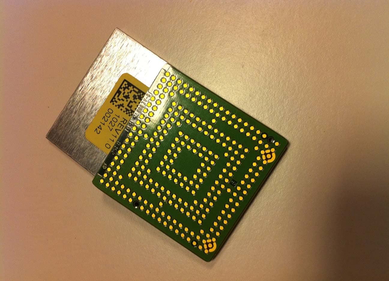
Click to zoom
Application Details
- Equipment Class
- JBP - Part 15 Class B Computing Device Peripheral
- Date of Grant
- Aug 18, 2010
- Application Purpose
- Original Equipment
- Date of Application
- Aug 18, 2010
- Equipment Note
- GSM/GPRS Module
- Company
- NXP Semiconductors
- Country
- France
Documents & Files
Document Text
Text extracted from the exhibit documents filed with the FCC. Open a document above to read the original.
Users Manual
NXP BU AUTOMOTIVE TELEMATICS ATOP 2.5G Project Documentation Raf Peeters OM12000 (ATOP) HW user manual Info Content Document type documentation Author Raf Peeters Author Role Application HWengineer Keywords ATOP2.5G, Telebox mini NXP Semiconductors OM1200 (ATOP) Project © NXP N.V. 2010 All rights reserved 2 / 27 Summary 1. Document purpose .................................................................................................. 3 Purpose ................................................................................................................................................... 3 Scope ....................................................................................................................................................... 3 Support ................................................................................................................................................... 3 History ..................................................................................................................................................... 3 2. Blockdiagram & photos ........................................................................................... 4 3. Powersupply & battery charger .............................................................................. 6 4. RF Antenna connections ........................................................................................ 10 GPRS ...................................................................................................................................................... 10 GPS ........................................................................................................................................................ 11 NFC ........................................................................................................................................................ 12 5. SIM card ................................................................................................................. 12 6. Clock microcontroller ............................................................................................ 13 7. USB......................................................................................................................... 14 8. PNX uart buffer ...................................................................................................... 15 9. CAN transceiver ..................................................................................................... 16 10. LED’s and buttons .................................................................................................. 18 Reset switch .......................................................................................................................................... 18 Ecall button ........................................................................................................................................... 18 LED’s ...................................................................................................................................................... 18 11. Accelerometer / Eeprom / SSI1 serial interface .................................................... 20 12. Audio connections ................................................................................................. 22 Analog audio in ..................................................................................................................................... 22 Analog audio out ................................................................................................................................... 23 12.1.1 Earphone ................................................................................................................... 23 12.1.2 Speaker ..................................................................................................................... 24 13. Board technology .................................................................................................. 25 14. Comments User Manual ........................................................................................ 27 15. FCC Class statement ............................................................................................. 27 NXP Semiconductors OM1200 (ATOP) Project © NXP N.V. 2010 All rights reserved 3 / 27 1. Document purpose Purpose Purpose of this document isto provide an uszer manual for OM12000 by describing Telebox Mini HW, which serves as reference HW platform for NXP SW development and demo within context of ATOP (OM12000) 2.5G project. Scope This document is intended for all (HW/SW engineers, customers) who need detailed understanding of Telebox Mini v3.x HW implementation and schematics. Support For HW questions, issue or any problem, please contact customer support. History The Telebox Mini has already some history. This new version 3.x which accommodates B2 ATOP version, and also some major changes are implemented in the power supply circuitry. Since this Telebox Mini aims to be a prototype for SW development and demo, there are a lot of jumper stuff options for test purpose which customers don’t need to copy. The default stuff option is indicated in the schematics by adding “dnp” “do not place” markers on components not stuffed by default. Main mechanical dimensions of this demo pcb were defined in order to fit in the small blue demobox GEPRO 8023 from ELPAC. As a result layout design and component choice had some restriction to fulfil the tight pcb area restriction. NXP Semiconductors OM1200 (ATOP) Project © NXP N.V. 2010 All rights reserved 4 / 27 2. Blockdiagram & photos NXP Semiconductors OM1200 (ATOP) Project © NXP N.V. 2010 All rights reserved 5 / 27 NXP Semiconductors OM1200 (ATOP) Project © NXP N.V. 2010 All rights reserved 6 / 27 3. Powersupply & battery charger The ATOP SiP module basically has 4 powersupply inputs: V_BATT_SW: supplies baseband PNX, frontend GPRS pow…
Text truncated - open the document above for the full version.
Cover Letter(s)
Request for confidentiality CONFIDENTIALITY REQUEST FOR OM12000, FCC ID: XXMOM12000 To Whom It May Concern: This letter serves as an official request for confidentiality under Rule Section §0.459 and 0.457(d). We requested the following documents to be held confidential: • Parts list • Block diagrams • Schematics • Operational Description The reason for this request is that these documents are company proprietary information that should never get into the possession of competitors, which would be harmful for our business. Also, in accordance with FCC Public DA 04-1705, we request short-term confidentiality for 180 days for exhibits: • Internal Photographs • External Photographs • User Manual • Test Setup Photos These exhibits contain pre-market information, which could give our competitors unfair advantage should this information be released before this product is actually introduced into the common marketplace. Do not hesitate to contact me if you have any additional questions. Ratingen, 2010/08/13 (Holger Leutfeld)
Test Report
Final Report on NXP automotive module OM12000 Final HW: B2 Final SW: stack v.:11;parameter v.:3 MDE_NXP_0901_FCCa acc. Title 47 CFR chapter I part 15 subpart B Report Reference: Jul y 20, 2010Date: Test Laboratory: 7 la yers AG Borsigstr. 11 DGA-PL-192/99-02 40880 Ratingen Germany Note: The following test results relate only to the devices specified in this document. This report shall not be reproduced in parts without the written approval of the test laboratory. 7 layers AG Aufsichtsratsvorsitzender h Registergerichth registered in: Borsigstrasse 11 Chairman of the Supervisory Board: Düsseldorf, HRB 44096 40880 Ratingen, Germany Markus Becker USt-IdNr h VAT N o.: Phone: +49 (0) 2102 749 0 Vorstandh Board: DE 203159652 Fax: +49 (0) 2102 749 350 Dr. H.-J. Meckelburg TAX No. 147/5869/0385 www.7Layers.com Wilfried Klassmann Reference: MDE_NXP_0901_FCCa acc. Title 47 CFR chapter I part 15 subpart B 1Administrative Data 1.1Project Data Sven LüngenPro ject Responsible: 2010/07/20Date Of Test Re port: 2009/11/13Date of first test: 2009/11/18Date of last test: 1.2Applicant Data Company Name:NXP Semiconductors 2 esplanade Anton Philips, Campus EffiScience, Colombelles BP2000 Street: 14906 Caen Cedex 9 City: FranceCountry: Contact Person:Mr. Hugues de Perthuis BU Automotive & IdentificationDepartment: +33 2.31.45.23.98Phone: +33 2.31.45.38.60Fax: 1.3Test Laboratory Data The following list shows all places and laboratories involved for test result generation: 7 layers DE Company Name :7 layers AG Street :Borsigstrasse 11 City :40880 Ratingen Country :Germany Contact Person :Mr. Michael Albert Phone :+49 2102 749 201 Fax :+49 2102 749 444 E Mail :[email protected] Laboratory Details Accreditation InfoLab IDIdentificationResponsible DAR-Registration no. DGA-PL-192/99-02Conducted EmissionsLab 1Mr. Robert Machulec Mr. Andreas Petz DAR-Registration no. DGA-PL-192/99-02Radiated EmissionsLab 2Mr. Robert Machulec Mr. Andreas Petz Page 2 of 23 Reference: MDE_NXP_0901_FCCa acc. Title 47 CFR chapter I part 15 subpart B 2.2Detailed Description of OUT Samples Sample : C04 OUT IdentifierNXP automotive module OM12000 Sample DescriptionSample 3 Serial No.E30B2#034 HW StatusB2 SW Statusstack v:1; parameter v:2 Date of Receipt2009/11/17 Low VoltageLow Temp.3.4 V-40 °C High Temp.High Voltage4.8 V85 °C Normal Temp.Nominal Voltage4.8 V21 °C Sample : D03 OUT IdentifierNXP automotive module OM12000 Sample DescriptionSample 4 Serial No.E30B2#035 HW StatusB2 SW Statusstack v:0; parameter v:2 Date of Receipt2009/11/03 Low VoltageLow Temp.3.4 V-40 °C High Temp.High Voltage4.8 V85 °C Normal Temp.Nominal Voltage4.8 V21 °C 2.3OUT Features Features for OUT: NXP automotive module OM12000 Allowed ValuesDesignationDescriptionSupported Value(s) Features for scope: FCC_v2 DCThe OUT is powered by or connected to DC Mains GSM850EUT supports GSM850 band 824MHz - 849MHz PantCpermanent fixed antenna connector, which may be built-in, designed as an indispensable part of the equipment PCS1900EUT supports PCS1900 band 1850MHz - 1910MHz SRDEUT is a short range device Page 4 of 23 Reference: MDE_NXP_0901_FCCa acc. Title 47 CFR chapter I part 15 subpart B 2.4Auxiliary Equipment AE No.Serial No.SW StatusHW StatusDescriptionType Designation AE 05GPS antenna GAACZ- A GPS antenna active AE 08Mifare 4KRFID TAG AE 07NXP Demoboard PN533 PCB1950-1 RFID antenna AE 02Silicon Laboratories CP2102-EB USB/ serial converter AE 04Stontronics 3A- 041WT05 Power Supply AE 01Telebox Mini debugpcb v1.1Controlling board AE 03Toshiba PTM91E- 02800TGR 87060248HLaptop 2.5Operating Mode(s) Ref.-No.Description 01Device is operating in GSM850 (TCH 190) , GPS+ RFID active 02Device is operating in GSM1900 (TCH 661) , GPS+ RFID active 2.6Setups used for Testing For each setup a relation is given to determine if and which samples and auxiliary equipment is used. The left side list all OUT samples and the right side lists all auxiliary equipment for the given setup. Sample No.Sample DescriptionAE No.AE Description Setup No.List of OUT samplesList of auxiliary equipment C04_FCC15b AE 05GPS antenna activeC04Sample 3Sample: AE 08RFID TAG AE 07RFID antenna AE 02USB/ serial converter AE 04Power Supply AE 01Controlling board AE 03Laptop D03_FCC15b AE 05GPS antenna activeD03Sample 4Sample: AE 08RFID TAG AE 07RFID antenna AE 02USB/ serial converter AE 04Power Supply AE 01Controlling board AE 03Laptop Page 5 of 23 Reference: MDE_NXP_0901_FCCa acc. Title 47 CFR chapter I part 15 subpart B 3Results 3.1General Available at the test laboratory. The results of the inspection are described on the following pages, where 'Conformity' or 'Passed' means that the certification criteria were verified and that the tested device is conform to the applied standard. In cases where 'Declaration' is printed, the required documents are available in the manufacturers product documentation. In cases where 'not applicable' is printed, the test case requirements are not relevant to the specific equipment implementation. Documentation of tested devices: Interpretation of the test results: 3.2List of the Applicable Body (Body for Scope: FCC_v2) DesignationDescription Part 15, Subpart B - Unintentional RadiatorsFCC47CFRChIPART15bRADIO FREQUENCY DEVICES 3.3List of Test Specification Test Specification:FCC part 2 and 15 Version10-1-09 Edition Title:PART 2 - GENERAL RULES AND REGULATIONS PART 15 - RADIO FREQUENCY DEVICES Page 6 of 23 Reference: MDE_NXP_0901_FCCa acc. Title 47 CFR chapter I part 15 subpart B 3.4Summary Test Case Identifier / Name SetupDate of TestResultTest (condition)Ref. Lab 15b.1 Conducted Emissions (AC Power Line) §15.107 15b.1; Mode = transmit2009/11/18C04_FCC15bLab 1Passed operating mode: 01 15b.2 Spurious Radiated Emissions §15.109 15b.2; Mode = transmit2009/11/13D03_FCC15bLab 2Passed operating mode: 02 Page 7 of 23 Reference: MDE_NXP_0901_FCCa acc. Title 47 CFR chapter I part 15 subpart B 3.5Detailed Results 3.5.115b.1 Conducted Emissions (AC Power Line) §15.107 Test: 15b.1; Mode = …
Text truncated - open the document above for the full version.
Test Setup Photos
Reference: Photo report to MDE_NXP_0901_FCCa 1Annex 1.1Additional Information for OUT Description front view back view Page 2 of 5 Reference: Photo report to MDE_NXP_0901_FCCa 1.2Additional Information for Test Plan Test setup for radiated measurements Page 3 of 5 Reference: Photo report to MDE_NXP_0901_FCCa Test setup fo conducted measurements (AC line) Page 4 of 5
Contact Information
Applicant
Saleem Kala-janssen(Systems & Applications Engineer)
Test Firm
7layers AGRobert Machulec
Technical Specifications
| # | Rule Parts | Frequency Range | Power Output |
|---|---|---|---|
| 1 | 15B | - | - |
Other Applications from NXP Semiconductors
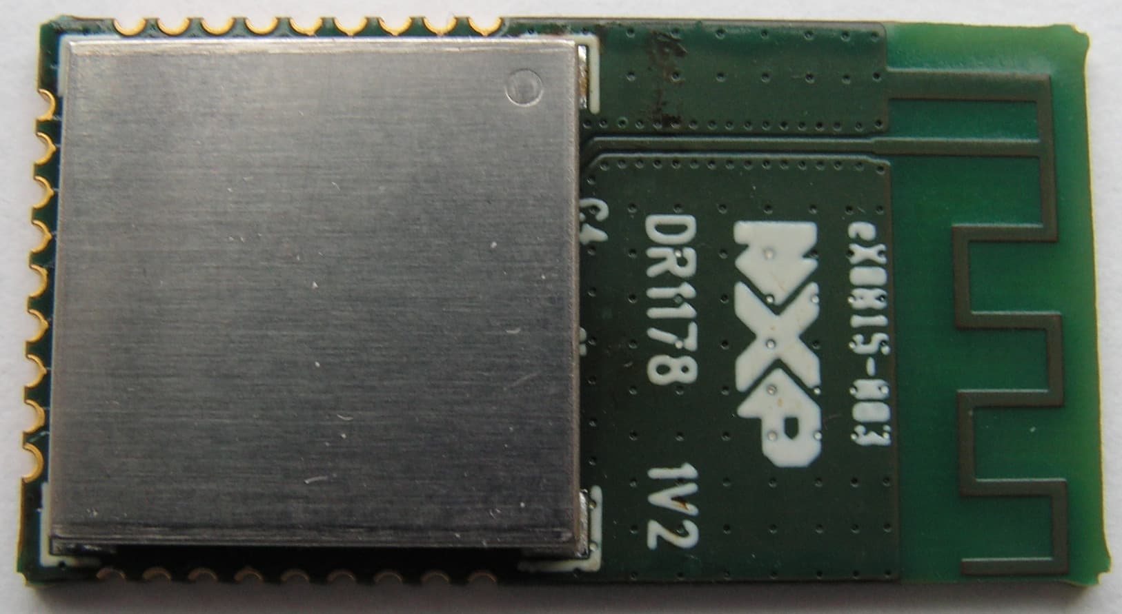
XXMJN5169M0
Nov 18, 2015Wireless microcontroller suitable for Zigbee applications
Equipment Class
DTS - Digital Transmission System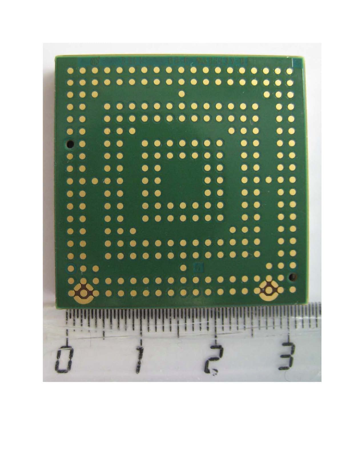
XXMOM12001000
Aug 30, 2012Automotive Telematics GSM/GPS Module
Equipment Class
PCB - PCS Licensed Transmitter