XXZ-INTC200GSIridium Certus satellite GMDSS terminal with WLAN
Intellian Technologies, Inc.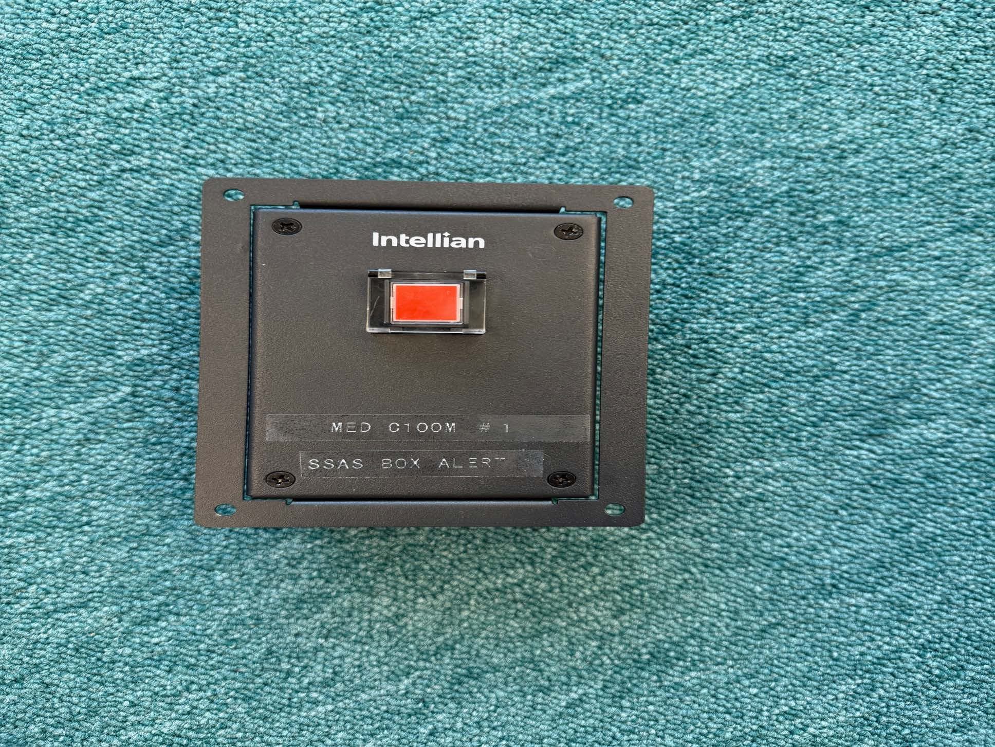
Click to zoom
Application Details
- Equipment Class
- TNB - Licensed Non-Broadcast Station Transmitter
- Date of Grant
- Feb 05, 2026
- Application Purpose
- Original Equipment
- Equipment Note
- Iridium Certus satellite GMDSS terminal with WLAN
- Frequency Range
- 1610.00000000 - 1626.50000000
- Company
- Intellian Technologies, Inc.
- Country
- South Korea
Documents & Files
Document Text
Text extracted from the exhibit documents filed with the FCC. Open a document above to read the original.
Users Manual
Intellian - Empowering Connectivity C200M GMDSS Installation Guide C200M -Intellian Certus GMDSS Terminal 2 Doc. No. UG-KXXXXX-V1.0 Serial number of the product This serial number will be required for all troubleshooting or service inquiries. © 2025 Intellian Technologies, Inc. All rights reserved. Intellian and the Intellian logo are trademarks of Intellian Technologies, Inc., registered in the U.S. and other countries. The C200M GMDSS is a trademark of Intellian Technologies, Inc. Intellian may have patents, patent applications, trademarks, copyrights, or other intellectual property rights covering subject matter in this document. Except as expressly provided in any written license agreement from Intellian, the furnishing of this document does not give you any license to these patents, trademarks, copyrights, or other intellectual property. All other logos, trademarks, and registered trademarks are the property of their respective owners. Information in this document is subject to change without notice. Every effort has been made to ensure that the information in this guide is accurate. Intellian is not responsible for printing or clerical errors. Disclaimer The information in this user guide is subject to change without prior notice throughout the product life cycle. The printed version of the guide is periodically updated, but it may contain inaccuracies or omissions compared to the most recent product information. The most up-to-date information is always available on our website at www.intelliantech.com. Document Information (HW/SW Version) This manual applies to the following HW and SW versions. Please note that the contents may be updated without notice and could differ from the actual product. HW Version SDTV0.6HandsetV0.4 Alarm Box V0.6SSAS Box Alert/TestV0.5 Junction BoxV0.4Alarm Unit*V5.0 * The Alarm Unit’s version is the main control version because the alarm unit has four types of PCBAs inside. SW Version SDT1.0.7SSAS Box Alert/Test1.1.1 Alarm Box #1, #2, #31.1.1BDU 2.0.1 Alarm Unit1.0.2ADU 1.0.5 Table of Contents 3 Table of Contents Chapter 1. Precautions 6 1.1 Warnings, Cautions, and Notes 6 1.2 General Precautions 6 Chapter 2. Certifications 8 Chapter 3. Introduction 9 3.1 Introduction of C200M GMDSS System 9 3.2 Iridium Satellite Network 10 3.3 Iridium Certus GMDSS SIM Card 11 Chapter 4. Planning Installation 12 4.1 Selecting Installation Site 12 4.1.1 Required Visibility for Iridium satellites 12 4.1.2 Separation to Obstacles 13 4.1.3 Separation to other antennas (eg UHF, VHF) 13 4.1.4 Co-existing with Inmarsat and Iridium L-Band terminals 14 4.1.5 Avoiding Radar Interference 15 4.1.6 RF Hazard Precautions 16 4.2 System Package 17 4.2.1 Above Deck Unit (ADU) 17 4.2.2 Below Deck Unit (BDU) 17 4.2.3 Safety Display Terminal 18 4.2.4 Packing List 19 4.3 System Cables (Customer Supplied) 21 4.3.1 Antenna RF Cable (Customer Supplied) 21 4.4 Unpacking Package 22 4.4.1 Unpacking Antenna Package 22 4.4.2 Unpacking SDT Package 24 4.5 Procedure for upgrading an in-service C200M installation to C200M GMDSS 26 4.5.1 Assessing an existing installation 26 4.5.2 New RF Hazard Label 26 4.5.3 Software Update 27 4.5.4 SIM card 27 4.5.5 Installation of the SDT, accessories and GMDSS system commissioning 27 Chapter 5. Installing ADU 28 5.1 Antenna Dimensions 28 5.2 ADU Mounting Hole Pattern 29 5.3 Mounting Antenna on Pole (Optional: MC-0003) 30 5.4 Vent Hole 31 5.5 Connecting Antenna RF Cable 32 5.6 Important Notice of Waterproofing Connector 33 5.6.1 Installing the Cold Shrink Tube on the Cable 33 5.6.2 Installing Waterproof Tape on the Cable (Optional) 34 C200M -Intellian Certus GMDSS Terminal 4 Chapter 6. Installing BDU 36 6.1 Selecting BDU Installation Site 36 6.2 BDU Dimensions 36 6.3 BDU Mounting Template 38 6.4 Mounting BDU 39 6.4.1 Direct Mounting Type 39 6.4.2 19” Rack Mounting Type (Optional) 39 6.5 Antenna System Configuration 41 6.5.1 Data Sessions and Voice Calls 42 6.6 BDU Cable Connection 43 6.6.1 BDU Back Panel View 43 6.6.2 BDU Connector Pinout Guide 43 6.6.3 Connecting DC Power to BDU 47 6.6.4 Connecting BDU to ADU (Antenna) 50 6.6.5 Connecting BDU to Devices using LAN Port (RJ45) 50 6.6.6 Connecting BDU to Device using WAN Port 51 6.6.7 Connecting BDU to POTS Phone (RJ14) 51 6.6.8 Connecting BDU to External Devices 52 6.6.9 Connecting Wi-Fi Antenna to BDU 52 6.6.10 Grounding Stud 52 6.6.11 Inserting SIM Card 53 6.7 DC Isolation Resistance 54 6.7.1 Grounding the system 54 Chapter 7. Installing the SDT 55 7.1 Selecting SDT Installation Site and Cautions 55 7.2 SDT Dimensions 56 7.3 Mounting SDT 57 7.3.1 Bracket Mounting Type 57 7.3.2 Flush Mounting Type 59 7.4 SDT System Configuration 62 7.4.1 Basic Configuration 62 7.4.2 Optional Configuration 63 7.5 SDT Cable Connection 64 7.5.1 SDT Front/Back Panel 64 7.5.2 SDT Connector Pinout Guide 66 7.6 Establishing SDT Connections 68 7.6.1 Connecting DC Power to the SDT 68 7.6.2 Connecting Main/ Emergency and Reserve Power Source 71 7.6.3 Connecting SDT to BDU using the BDU Port 72 7.6.4 Connecting SDT to Devices using the LAN Port 72 7.6.5 Connecting SDT to a Keyboard using the USB Port 73 7.6.6 Connecting the SDT to the Ship’s Grounding System 73 7.7 Power Consumption 74 7.8 DC Isolation Resistance & Grounding 75 7.8.1 Connecting SDT Chassis Ground/ DC Power cable/ Isolation resistance 75 7.8.2 Connecting BDU Chassis Ground/ DC Power cable/ Isolation resistance 76 7.9 Galvanic Isolated Power Supply 77 Table of Contents 5 7.9.1 Connecting VAC IN & Chassis Ground 77 7.9.2 Connecting VDC IN & Chassis Ground 78 7.9.3 Connecting Battery Power Supply with AC/DC Galvanic isolated Charger 78 Chapter 8. Installing Handset 79 8.1 Selecting Handset Installation Site 79 8.2 Dimensions 79 8.3 Overview 80 8.4 Connecting the Handset Cable to the SDT 81 8.4.1 Connecting the Handset to the Front Panel of the SDT 81 8.4.2 Connecting the Handset to the Back Panel of the SDT (Optional) 81 Chapter 9. Operating Install Wizard 82 9.1 Turning On System …
Text truncated - open the document above for the full version.
Users Manual
Intellian - Empowering Connectivity C200M/C700 GMDSS Operation Guide C200M/C700 -Intellian Certus GMDSS Terminal ii Doc. No. UG-KG6017-V1.0 Serial number of the product This serial number will be required for all troubleshooting or service inquiries. © 2025 Intellian Technologies, Inc. All rights reserved. Intellian and the Intellian logo are trademarks of Intellian Technologies, Inc., registered in the U.S. and other countries. The C200M/C700 GMDSS is a trademark of Intellian Technologies, Inc. Intellian may have patents, patent applications, trademarks, copyrights, or other intellectual property rights covering subject matter in this document. Except as expressly provided in any written license agreement from Intellian, the furnishing of this document does not give you any license to these patents, trademarks, copyrights, or other intellectual property. All other logos, trademarks, and registered trademarks are the property of their respective owners. Information in this document is subject to change without notice. Every effort has been made to ensure that the information in this guide is accurate. Intellian is not responsible for printing or clerical errors. Disclaimer The information in this user guide is subject to change without prior notice throughout the product life cycle. The printed version of the guide is periodically updated, but it may contain inaccuracies or omissions compared to the most recent product information. The most up-to-date information is always available on our website at www.intelliantech.com. Document Information (HW/SW Version) This manual applies to the following HW and SW versions. Please note that the contents may be updated without notice and could differ from the actual product. HW Version SDTV0.6HandsetV0.4 Alarm Box V0.6SSAS Box Alert/TestV0.5 Junction BoxV0.4Alarm Unit*V5.0 * The Alarm Unit’s version is the main control version because the alarm unit has four types of PCBAs inside. SW Version SDT1.0.7SSAS Box Alert/Test1.1.1 Alarm Box #1, #2, #31.1.1Alarm Unit1.0.2 BDU (C200M GMDSS)2.0.1ADU (C200M GMDSS)1.0.5 BDU (C700 GMDSS)3.0.1ADU (700 GMDSS)1.0.2 Precautions iii Precautions Warnings, Cautions, and Notes WARNING, CAUTION, and NOTE statements are used throughout this manual to emphasize important and critical information. You must read these statements to help ensure safety and to prevent product damage. The statements are defined below. WARNING WARNING WARNING indicates a potentially hazardous situation that if not avoided, could result in death or serious injury. CAUTION CAUTION CAUTION indicates a potentially hazardous situation that if not avoided, could result in minor or moderate injury or damage to equipment. It may also be used to alert users about unsafe practices. NOTE NOTE A NOTE statement is used to notify people of installation, operation, programming, or maintenance information that is important, but not hazard-related. General Precautions Before you use the antenna, make sure that you have read and understood all safety requirements. *Shock Hazard: To minimize shock hazard and to protect against lightning, the equipment cabinets must be connected to the ship’s metallic hul. Make sure the system is correctly grounded and power is off when installing, configuring, and connecting components. *Do not operate in an explosive atmosphere: Do not operate the equipment in explosive environments or in the presence of flammable gases. Operating this equipment in such an environment causes a definite safety hazard. *Keep away from living circuits: Operating personnel must at all times observe all safety regulations. Do not replace components or make adjustment inside the equipment with any power supply turned on. Under certain conditions, dangerous potentials may exist in the power supplies even with the power cable removed. To avoid injuries, always remove the power and discharge a circuit before touching it. C200M/C700 -Intellian Certus GMDSS Terminal iv DISTRESS ALERT Transmitting the Distress Alert 1. Open the cover of the DISTRESS key and press and hold the key for 3 seconds. DISTRESS KEY DISTRESS COVER NOTE NOTE The DISTRESS key is covered to prevent accidental operation. An intermittent audible alarm will sound, and the key will blink in red. A countdown screen (3s, 2s, 1s) will appear. The Distress Alert will be sent when the countdown reaches 0 seconds, and both light and sound becomes steady. When the DISTRESS key is released to sound will stop. When the Distress Alert transmission starts, the screen is updated to show: •The RCC that the Distress Alert has been sent to. •Displays the current status of the Distress Alert (options include Sending, Sent, Delivered, Canceling, Acknowledged) •The user can change the Nature of distress by selecting a different option from the drop down list (see section 4.1.2). The Call button can be used to initiate a Distress Voice call with the RCC. If Auto Dial is set, a Distress Voice call will automatically be initiated when the Distress Alert status changes to Delivered. Introduction v Canceling Distress Alert You can cancel the Distress Alert while it is being sent or while waiting for its acknowledgment as follows: 1. Select the CANCEL option button. A pop-up window will be displayed on the screen. 2. Press the Yes button to proceed with the cancellation ot the Distress Alert. 3. A pop-up confirms that the Distress Alert has been cancelled. C200M/C700 -Intellian Certus GMDSS Terminal vi Table of Contents Precautions iii DISTRESS ALERT iv Chapter 1. Certifications 1 Chapter 2. Introduction 2 2.1 Introduction of C200M/C700 GMDSS System 2 2.2 Iridium Satellite Network 3 2.3 Iridium Certus GMDSS SIM Card 4 Chapter 3. Operating SDT 5 3.1 Controls 5 3.2 Handset 6 3.3 Turning On/Off Power 6 3.4 Home screen 7 3.4.1 Status Bar 7 3.4.2 Menu Bar 8 3.4.3 Content Area 9 3.5 SDT Menu 10 3.6 Display 11 Chapter 4. GMDSS Services 13 4.1 Distress Alert & Distress Voice Call 13 4.1.1 Activation of Distress 13 4.1.2 …
Text truncated - open the document above for the full version.
Users Manual
Install SDT 63 7.4.2 Optional Configuration C200 Above Deck Unit CP-T1A1 SDT7000C Below Deck Uni t HS7000 / HC7000 Sa fety Di splay Terminal Dummy Handset Hand set Spiral CableEthernet CableCoaxial Cable Printer SRP- 350plusIII SPR- 8695TU Keyboard EDS-205A Ethernet switches PSU180D JB1000 AC/ DC Power Supply Unit AU 1000 Junction Box Alarm Unit AB1000 Alarm Box AB1000 Alarm Box AB1000 SB7000T Alarm Box SB7000A SSAS Box Test SB7000A SSAS Box Alert SSAS Box Alert Ethernet Cable IN-RPCAP08G5E-PLUG CAN Cable IN-RPCAP08G5E-PLUG RS-232 CAN-BUS 2x2x0.75 120Ω DC24V NOTE NOTE •CAM-HMI Installation Location: - At least one Central Alert Management HMI (CAM-HMI) device must be installed at the navigation and maneuvering workstation. - If necessary, it can also be additionally installed at the monitoring workstation. •Attention: - If an Integrated Navigation System (INS) is already installed and operational on-board, installing an additional, separate Central Alert Management (CAM) system alongside this equipment is not permitted. The INS system must include or integrate the CAM functionality. C200M -Intellian Certus GMDSS Terminal 64 7.5 SDT Cable Connection 7.5.1 SDT Front/Back Panel The following figures show the SDT front and back panels. Front ❶ ❷ ❹ ❸ ❺ No.KeyFunction ① Dimmer knobControl the LCD screen brightness by the dimmer knob. ② DISTRESS keyPress and hold the button for three seconds to transmit the Distress Alert. Note: DISTRESS button is covered by transparent cover to prevent user from accidental operation. ③ Front speakerFront speaker is located inside the housing. ④ Handset portConnect the provided handset (HS7000). (It can also be connected to the rear 8P port.) ⑤ 7" LCD screenDisplays the user interface including menu, function, message, etc. Install SDT 65 Rear ❶ ❷ ❹ ❺ ❻ ❼ ❸ No.PortFunction ① LAN Enter the APTUS web UI by connecting the LAN port to the EDS-205A (LAN switch) or a PC/LAPTOP. •The web UI displays information such as the C200M link state. ② USB Connect the optionally provided SPR-8695TU (keyboard). Connect the USB flash drive. (only supports FAT32). ③ DATA Connect the provided IN-CCCAF14FCC-03H cable to the JB1000. This cable supports RS-422, CAN, and RS-232 (printer) communications. ④ GNDIt enhances robustness against electromagnetic interference, including ESD, bursts, noise, etc. •If possible, connect the shield to the earth using the cable. ⑤ BDU Connect the BDU using an Ethernet cable. ⑥ HANDSET Connect the provided handset. (It can also be connected to the front 8P connector.) ⑦ DC24V Connect the provided IN-CCBAF12FBB-03H cable to the JB1000. •This cable supplies DC power from the PSU180D and supports RS-422 communication. C200M -Intellian Certus GMDSS Terminal 66 7.5.2 SDT Connector Pinout Guide Handset (Front/Rear) Connector IEC 320 C14 Plug Male PinSignal 1MIC+BIAS 2Det_Key_ADC 3Speaker + 4Speaker - 5Hook_ADC 6AF_1.8V 7Shield 8GND Power Connector (DC Power) Font view, Panel lock, 12 pin male PinSignalWire color 1BATT- (DC 24V -)Black 2BATT- (DC 24V -)Brown 3BATT+ (DC 24V +)Red 4BATT+ (DC 24V +)Orange 5EARTH (Isolation, GND)Yellow 6EARTH (Isolation, GND)Green 7Not ConnectBlue 8EXT1_RX A (Input, IEC61162-1/2)Purple 9EXT1_RX B (Input, IEC61162-1/2)Gray 10EXT1_GNDWhite 11EXT1_TX Z (Output, IEC61162-1/2)Pink 12EXT1_TX Y(Output, IEC61162-1/2)Light Green Install SDT 67 DATA Connector (DC Power) Font view, Panel lock, 14 pin male PinSignalWire color 1EXT2_RX A (Input, IEC61162-1/2)Black 2EXT2_RX B (Input, IEC61162-1/2)Brown 3EXT1_GNDRed 4EXT2_TX Z (Output, IEC61162-1/2)Orange 5EXT2_TX Y(Output, IEC61162-1/2)Yellow 6DC_OUT + (DC 24V+ Out)Green 7DC_OUT – (DC 24V- Out)Blue 8CAN_H (IEC61162-3)Purple 9CAN_L (IEC61162-3)Gray 10EXT_EARTH (Isolation, GND)White 11RS-232 RX (Output, IEC61162-1/2)Pink 12RS-232_GNDLight Green 13RS-232 TX (Output, IEC61162-1/2)Black/White 14Not ConnectBlack/White BDU / LAN Connector (LAN) 12345678 RJ-45 Female PinSignal 1Tx+ 2Tx- 3Rx+ 4N/C 5N/C 6Rx- 7N/C 8N/C USB Connector USB A Female PinSignal 1VBUS 2USB DM(-) 3USB DP(+) 4GND C200M -Intellian Certus GMDSS Terminal 68 7.6 Establishing SDT Connections 7.6.1 Connecting DC Power to the SDT Directly Connecting Power Cable to the SDT 1. The wire should be terminated with a ring connector (Optional) as shown below: •Positive (BATT + / DC 24 +): Red and Orange wires •Negative (BATT - / DC 24 -): Black and Brown wires •Earth: Yellow and Green wires 2. Remove the safety protection cover of the Power Supply. 3. Unscrew the “+” terminal on DC 24V OUT using a Phillips screwdriver. Insert the ring connector of the Red and Orange (positive) wires into the terminal and tighten the screw back into the terminal. 4. Unscrew the “-” terminal on DC 24V OUT using a Phillips screwdriver. Insert the ring connector of the Black and Brown (negative) wires into the terminal and tighten the screw back into the terminal. 5. Unscrew the “⏚” terminal on DC 24V OUT using a Phillips screwdriver. Insert the ring connector of the Yellow and Green (earth) wires into the terminal and tighten the screw back into the terminal. PinSignalWire color 1BATT- (DC 24V -) ⃝ Black 2BATT- (DC 24V -) ⃝ Brown 3BATT+ (DC 24V +) ⃝ Red 4BATT+ (DC 24V +) ⃝ Orange 5EARTH (Isolation, GND, Drain) ⃝ Yellow 6EARTH (Isolation, GND, Drain) ⃝ Green Power Supply 6. Replace the safety protection cover of the Power Supply. 7. Connect the 12-pin power connector to the DC 24V port on the back of the SDT. 8. Finger-tighten the lock ring on the waterproof housing connector to ensure a secure and waterproof connection. SDT Install SDT 69 Connecting Power Cable to SDT Junction Box Power Supply To connect the power to the junction box, you will need to purchase the Junction Box and Power Supply (PSU-18D) separately. These items are provided in a separate box when supplied. 1. Connect the PSU-18D to the junction box using the power cable: a. Unscrew the “+” terminal on DC 24V OUT using a Phillips screwdriver. Insert the ring connector of the Red (positive) wire in…
Text truncated - open the document above for the full version.
Users Manual
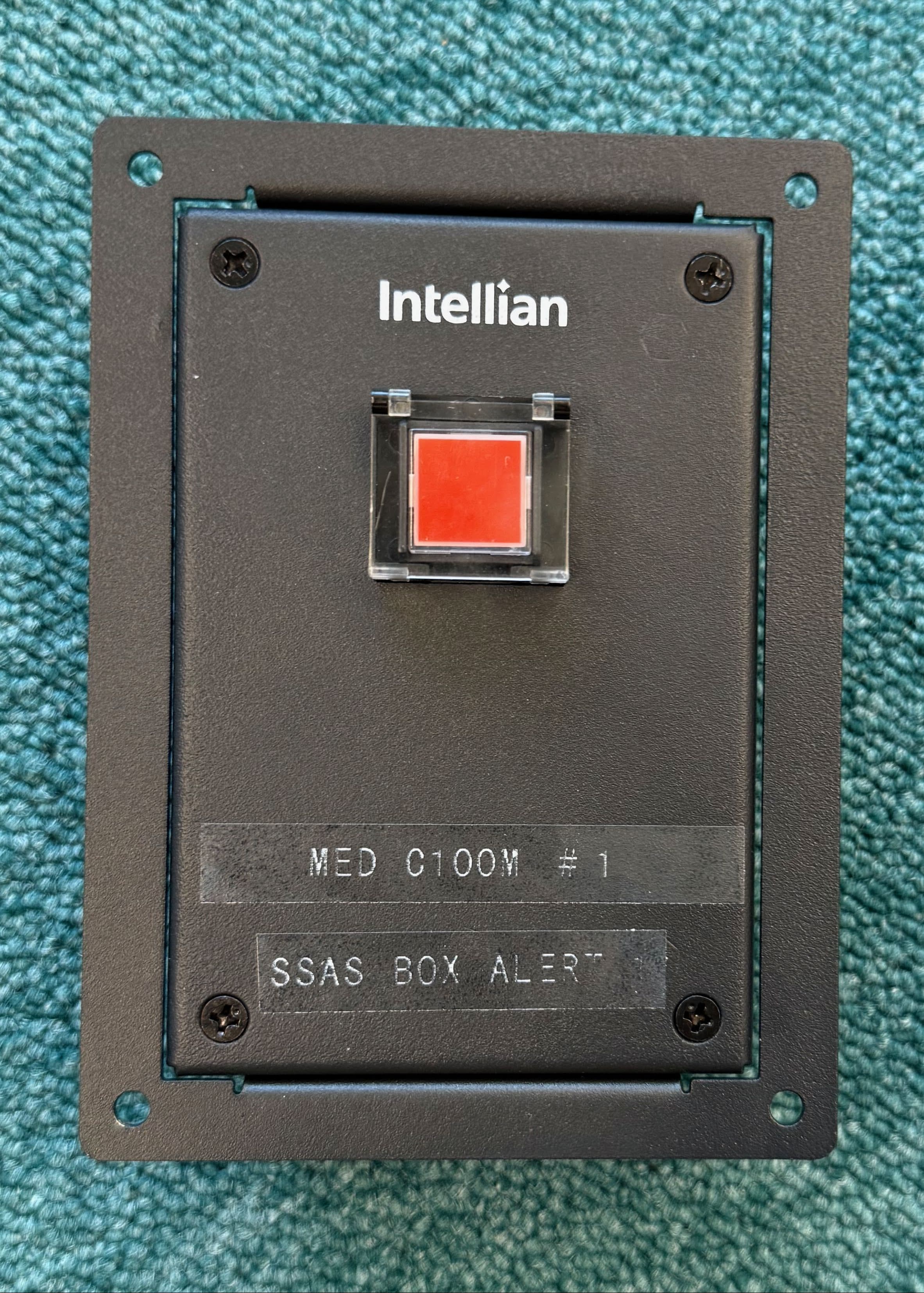
C200M/C700 -Intellian Certus GMDSS Terminal 66 Chapter 9. Ship Security Alert System (SSAS) service C200M/C700 GMDSS supports SSAS (Ship Security Alert System) functionality. When enabled, the SSAS service allows the transmission of security alerts from the vessel in response to security threats. When activated by the ship’s master or crew, the system automatically sends alert messages to predefined recipients including the ship operator and relevant authorities. This system enables rapid response to maritime security threats such as piracy, terrorism, or armed robbery. 9.1 SSAS Box Alert and SSAS Box Test SSAS Box Alert The SSAS Box Alert, as shown in the illustration, has a single red latched button with a built-in LED light. When you press the button once, it stays pressed; pressing it again will release it back to its original position. There is a clear over that protects the button from being accidentally pressed. You can use this button in two ways: •When used alone, it activates the SSAS Alert. •When used together with the Test button, it triggers a Test Alert. SSAS Box Test The SSAS Box Test has a single green button with a built-in LED indicator. This is a momentary button, so it returns to its original position immediately after you release it. When you use this button together with the SSAS Box Alert, it activates the SSAS Test Alert, and the LED blinks to indicate that the test alert is active. SSAS 67 9.2 Activating a SSAS Alert Activating a SSAS Alert: 1. Firmly press one of the SSAS Box Alert buttons so that it latches into the down position. 2. If the SSAS Alert was activated by mistake or you wish to cancel the alert before the message is sent, press the button again within the 30-second window (the SSAS Box Alert button uses a latched mechanism) to release the button. 3. If the button remains latched for 30 seconds, a SSAS Alert message is automatically transmitted to the designated recipient. 4. After this, the alert message will continue to be retransmitted at the interval configured in the SSAS configuration menu. Cancelling an SSAS Alert (after transmission): 1. Press the SSAS Box Alert button again (the SSAS Box Alert button uses a latched mechanism) to release the button and stop the active SSAS Alert. 2. The system then sends a cancellation message to the recipient. 9.3 Activating a SSAS Test Alert Activating a SSAS Test Alert: 1. Press and hold the SSAS Box Test button. 2. Continue holding the SSAS Box Test button, and press one of the SSAS Box Alert buttons so the it is latched in the down position. 3. When the SSAS Test Alert is activated, the LED on the SSAS Box Test button will blink at 250ms intervals. You may then release the SSAS Box Test button, but the SSAS Box Alert button must remain latched. 4. To cancel before transmission: If the test was activated by mistake, press the SSAS Box Alert button again within the 30-second window to release the button. The SSAS Box Test button LED will turn off when deactivated. 5. Automatic transmission: If the SSAS Box Alert button remains latched for 30 seconds, a test alert message is automatically transmitted to the designated recipient, and the LED on the SSAS Box Test button will blink more quickly at 100ms intervals. 6. After transmission, the test alert message will continue to be retransmitted at the configured interval. Cancelling a SSAS Test Alert (after transmission): 1. Press the SSAS Box Alert button again (the SSAS Box Alert button uses a latched mechanism) to release the button and stop the active test alert. When the test alert is stopped, the LED on the SSAS Box Test button will turn off. 2. The system then sends a cancellation message to the recipient. C200M/C700 -Intellian Certus GMDSS Terminal 68 9.4 SSAS Status Go to Menu → Non-GMDSS Function → SSAS. The SSAS Status section provides information on the SSAS service status. The key parameters shown in the SSAS Status display are: ❶ ❷ ❸ No.ItemDescription ① Status Displays the current status of the SSAS service. •Not Configured: Required settings have not been completed, so the service is unavailable. •Idle: The system is on standby, ready to send an alert or test alert as needed. •Alert ready: The system is waiting to send an alert. Cancellation is possible before transmission. •Alert test ready: The system is waiting to send a test alert. Cancellation is possible before transmission. •Sending alert: The system is in the process of transmitting an alert. •Sending alert test: The system is in the process of transmitting a test alert. •Sending alert cancellation: The system is in the process of canceling an alert after it has been sent. •Sending alert test cancellation: The system is in the process of canceling a test alert after it has been sent. ② Provider (ASP) Displays the Application Service Provider (ASP) responsible for handling SSAS transmissions. If no ASP is assigned, it shows “N/A” Otherwise, it displays the assigned ASP name (e.g., polestar). ③ Alert Interval Displays the configured alert me ssage sending interval. •If no alert interval is configured, it shows “No alert interval configured.” •If an alert interval is set, it displays the configured value (e.g., 10 min, 20 min, 30 min, etc.). SSAS 69 9.5 SSAS Setting Go to Menu → Non-GMDSS Function → SSAS → Configuration. The SSAS Setting section allows you to configure the following parameters for the vessel’s SSAS system. The key settings are: ❶ ❷ ❸ ❹ No.ItemDescription ① Destination Designate the contact information (Email or SMS) for the recipient or center that receives an alert message. ② CSO (Chief Security Officer) Enter the name and phone number of the Chief Security Officer. This information is not used for transmitting SMS; it is for reference only. ③ Secondary CSO If the flag state requires that information, enter the name and phone number of the Secondary Chief Security Officer. This information is not used for transmitting SMS; it is for reference only. ④ Alert Interval Set the…
Text truncated - open the document above for the full version.
RF Exposure Info
Page 1 of 1 1 RF Exposure MPE Calculation Prediction of MPE limit at a given distance For purposes of these requirements mobile devices are defined by the FCC as transmitters designed to be used in other than fixed locations and to generally be used in such a way that a separation distance of at least 20 centimeters is normally maintained between radiating structures and the body of the user or nearby persons. These devices are normally evaluated for exposure potential with relation to the MPE limits. As the 20 cm separation specified under FCC rules may not be achievable under normal operation of the EUT, an RF exposure calculation is needed to show the minimum distance required to be less than the power density limit, as required under FCC rules. Equation from IEEE C95.1 Where: S = power density R = distance to the centre of radiation of the antenna EIRP = EUT Maximum power Result Channel Frequency (MHz) EIRP (mW) Power density limit (S) (mW/cm 2 ) Distance (R) cm required to be less than the power density limit 1616.333 16218.1 1.0 35.9 1625.666 20417.4 1.0 40.3 4 arranged-re 4 2 S EIRP R R EIRP S==
Test Setup Photos
Report Number: TRA-061097-47-00A Page 14 of 37 9.2 General Set-up Photograph The following photograph shows basic EUT set-up:
Test Setup Photos
Report Number: TRA-061097-44-00B RF759 issue 9.0 Page 18 of 26 8.8 Test Photograph
Test Report
Report on the Radio Testing For Intellian Ltd on C200 M Report no. TRA-061097-47-00A 12th March 2024 REPORT ON THE RADIO TESTING OF A Intellian Ltd C200 M WITH RESPECT TO SPECIFICATION THE FCC RULES CFR 47, Part 25 TEST DATE: 13th February to 21st February 2024 Written by: S Hodgkinson Radio Test Engineer Approved by: J Charters Laboratory Manager Date: 12th March 2024 Disclaimers: [1] THIS DOCUMENT MAY BE REPRODUCED ONLY IN ITS ENTIRETY AND WITHOUT CHANGE [2] THE RESULTS CONTAINED IN THIS DOCUMENT RELATE ONLY TO THE ITEM(S) TESTED Report Number: TRA-061097-47-00A Issue: A Report Number: TRA-061097-47-00A Page 3 of 37 1 Revision Record Issue Number Issue Date Revision History A 12th March 2024 Original Report Number: TRA-061097-47-00A Page 4 of 37 2 Summary TEST REPORT NUMBER: TRA-061097-47-00A WORKS ORDER NUMBER: TRA-061097-02 PURPOSE OF TEST: Certification TEST SPECIFICATION: CFR47, Part 25 EQUIPMENT UNDER TEST (EUT): C200 M FCC IDENTIFIER: 2BAX4-INTC200M MANUFACTURER/AGENT: Intellian Ltd ADDRESS: 4th Floor, The Charter Building, Charter Place, Uxbridge UB8 1JG United Kingdom CLIENT CONTACT: Sophie Michel 07546740157 [email protected] TEST DATE: 13th February to 21st February 2024 TESTED BY: S Hodgkinson Element Report Number: TRA-061097-47-00A Page 5 of 37 2.1 Test Summary Test Method and Description Requirement Clause Applicable to this equipment Result / Note FCC PART 2 FCC PART 25 RF Power Output 2.1046 25.204 (a) Pass Emission Limitations 2.1049 25.202 (f) Pass Protection of Radio Navigation satellite services 2.1051 25.202 (c) 25.216 (f) Pass Spurious emissions- Radiated 2.1053 25.202 (f) 25.213 Pass Frequency Stability 2.1055 25.202 (d) Pass Notes: The results contained in this report relate only to the items tested, in the condition at time of test, and were obtained in the period between the date of initial receipt of samples and the date of issue of the report. The apparatus was set-up and exercised using the configurations, modes of operation and arrangements defined in this report only. Any modifications made are identified in Section 8 of this report. Particular operating modes, apparatus monitoring methods and performance criteria required by the standards tested to have been performed except where identified in Section 5.2 of this test report (Deviations from Test Standards). The decision rule for compliance is not inherent within this specification and compliance is based on the customer requesting a simple acceptance rule based on understanding and acceptance of Elements Measurement Uncertainty values. Report Number: TRA-061097-47-00A Page 6 of 37 3 Contents 1 Revision Record ............................................................................................................................... 3 2 Summary .......................................................................................................................................... 4 2.1 Test Summary ........................................................................................................................... 5 3 Contents ........................................................................................................................................... 6 4 Introduction ....................................................................................................................................... 7 5 Test Specifications ........................................................................................................................... 8 5.1 Normative References .............................................................................................................. 8 5.2 Deviations from Test Standards ................................................................................................ 8 6 Glossary of Terms ............................................................................................................................ 9 7 Equipment Under Test ................................................................................................................... 10 7.1 EUT Identification .................................................................................................................... 10 7.2 System Equipment .................................................................................................................. 10 7.3 EUT Mode of Operation .......................................................................................................... 10 7.4 EUT Radio Parameters ........................................................................................................... 10 7.4.1 General .....…
Text truncated - open the document above for the full version.
Contact Information
Applicant
JunHui Lee(Senior Manager)
[email protected]Fax: +82-2-515-4923
Technical Contact
Intellian Technologies USA IncorporatedYoon James
11, Studebaker · Irvine, 92618 · United States
Test Firm
Element Materials Technology Warwick LtdNeil Roche
[email protected]Fax: 44 1926 478479
Technical Specifications
| # | Rule Parts | Frequency Range | Power Output | Emission | Tolerance |
|---|---|---|---|---|---|
| 1 | 25,8 | 1.61 GHz - 1.63 GHz | 2.57 W | 41K7Q7W | 0.27ppm |
| 2 | 25,8 | 1.61 GHz - 1.63 GHz | 2.45 W | 83K4Q7W | 0.27ppm |
| 3 | 25,8 | 1.61 GHz - 1.63 GHz | 9.77 W | 334KQ7W | 0.27ppm |
| 4 | 25,8 | 1.61 GHz - 1.63 GHz | 20.42 W | 667KQ7W | 0.27ppm |
Other Applications from Intellian Technologies, Inc.
XXZ-INTC700GS
May 19, 2026Maritime Iridium Certus satellite Global Maritime Distress and Safety System (GMDSS)
Equipment Class
JAD - Part 15 Class A Digital DeviceXXZ-OW10HX
Jun 26, 2024Compact User Terminal Antenna
Equipment Class
TNB - Licensed Non-Broadcast Station Transmitter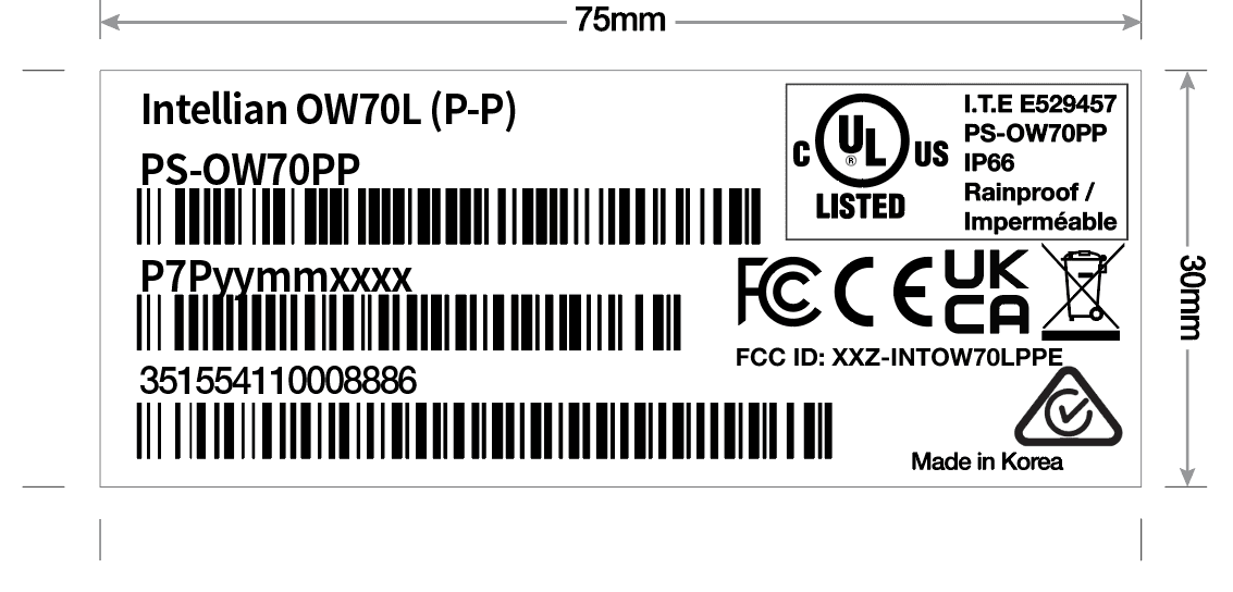
XXZ-INTOW70LPPE
Dec 03, 2023OW70L (P-P)
Equipment Class
TNB - Licensed Non-Broadcast Station TransmitterXXZ-INTFB500
Oct 25, 2022Marine Fleet Broadband
Equipment Class
TNB - Licensed Non-Broadcast Station Transmitter
XXZ-INTOW70LDAC
Jul 28, 2021OneWeb OW70L UT (12dB/K)
Equipment Class
TNB - Licensed Non-Broadcast Station Transmitter