XXZ-INTC700GSMaritime Iridium Certus satellite Global Maritime Distress and Safety System (GMDSS)
Intellian Technologies, Inc.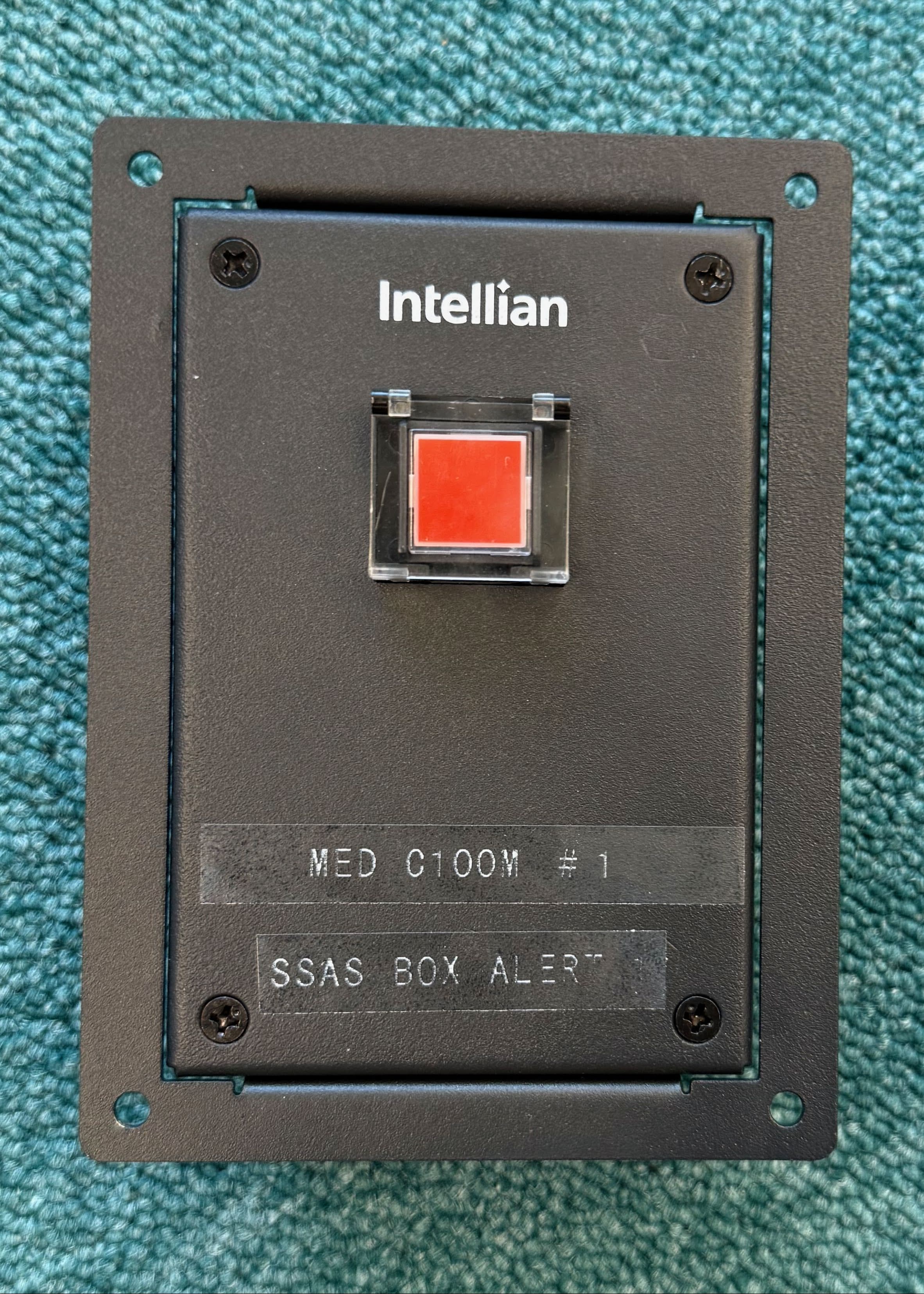
Click to zoom
Application Details
- Equipment Class
- JAD - Part 15 Class A Digital Device
- Date of Grant
- May 19, 2026
- Application Purpose
- Original Equipment
- Equipment Note
- Maritime Iridium Certus satellite Global Maritime Distress and Safety System (GMDSS)
- Company
- Intellian Technologies, Inc.
- Country
- South Korea
Documents & Files
Document Text
Text extracted from the exhibit documents filed with the FCC. Open a document above to read the original.
Users Manual
Intellian - Empowering Connectivity C200M/C700 GMDSS Operation Guide C200M/C700 -Intellian Certus GMDSS Terminal ii Doc. No. UG-KG6017-V1.0 Serial number of the product This serial number will be required for all troubleshooting or service inquiries. © 2025 Intellian Technologies, Inc. All rights reserved. Intellian and the Intellian logo are trademarks of Intellian Technologies, Inc., registered in the U.S. and other countries. The C200M/C700 GMDSS is a trademark of Intellian Technologies, Inc. Intellian may have patents, patent applications, trademarks, copyrights, or other intellectual property rights covering subject matter in this document. Except as expressly provided in any written license agreement from Intellian, the furnishing of this document does not give you any license to these patents, trademarks, copyrights, or other intellectual property. All other logos, trademarks, and registered trademarks are the property of their respective owners. Information in this document is subject to change without notice. Every effort has been made to ensure that the information in this guide is accurate. Intellian is not responsible for printing or clerical errors. Disclaimer The information in this user guide is subject to change without prior notice throughout the product life cycle. The printed version of the guide is periodically updated, but it may contain inaccuracies or omissions compared to the most recent product information. The most up-to-date information is always available on our website at www.intelliantech.com. Document Information (HW/SW Version) This manual applies to the following HW and SW versions. Please note that the contents may be updated without notice and could differ from the actual product. HW Version SDTV0.6HandsetV0.4 Alarm Box V0.6SSAS Box Alert/TestV0.5 Junction BoxV0.4Alarm Unit*V5.0 * The Alarm Unit’s version is the main control version because the alarm unit has four types of PCBAs inside. SW Version SDT1.0.7SSAS Box Alert/Test1.1.1 Alarm Box #1, #2, #31.1.1Alarm Unit1.0.2 BDU (C200M GMDSS)2.0.1ADU (C200M GMDSS)1.0.5 BDU (C700 GMDSS)3.0.1ADU (700 GMDSS)1.0.2 Precautions iii Precautions Warnings, Cautions, and Notes WARNING, CAUTION, and NOTE statements are used throughout this manual to emphasize important and critical information. You must read these statements to help ensure safety and to prevent product damage. The statements are defined below. WARNING WARNING WARNING indicates a potentially hazardous situation that if not avoided, could result in death or serious injury. CAUTION CAUTION CAUTION indicates a potentially hazardous situation that if not avoided, could result in minor or moderate injury or damage to equipment. It may also be used to alert users about unsafe practices. NOTE NOTE A NOTE statement is used to notify people of installation, operation, programming, or maintenance information that is important, but not hazard-related. General Precautions Before you use the antenna, make sure that you have read and understood all safety requirements. *Shock Hazard: To minimize shock hazard and to protect against lightning, the equipment cabinets must be connected to the ship’s metallic hul. Make sure the system is correctly grounded and power is off when installing, configuring, and connecting components. *Do not operate in an explosive atmosphere: Do not operate the equipment in explosive environments or in the presence of flammable gases. Operating this equipment in such an environment causes a definite safety hazard. *Keep away from living circuits: Operating personnel must at all times observe all safety regulations. Do not replace components or make adjustment inside the equipment with any power supply turned on. Under certain conditions, dangerous potentials may exist in the power supplies even with the power cable removed. To avoid injuries, always remove the power and discharge a circuit before touching it. C200M/C700 -Intellian Certus GMDSS Terminal iv DISTRESS ALERT Transmitting the Distress Alert 1. Open the cover of the DISTRESS key and press and hold the key for 3 seconds. DISTRESS KEY DISTRESS COVER NOTE NOTE The DISTRESS key is covered to prevent accidental operation. An intermittent audible alarm will sound, and the key will blink in red. A countdown screen (3s, 2s, 1s) will appear. The Distress Alert will be sent when the countdown reaches 0 seconds, and both light and sound becomes steady. When the DISTRESS key is released to sound will stop. When the Distress Alert transmission starts, the screen is updated to show: •The RCC that the Distress Alert has been sent to. •Displays the current status of the Distress Alert (options include Sending, Sent, Delivered, Canceling, Acknowledged) •The user can change the Nature of distress by selecting a different option from the drop down list (see section 4.1.2). The Call button can be used to initiate a Distress Voice call with the RCC. If Auto Dial is set, a Distress Voice call will automatically be initiated when the Distress Alert status changes to Delivered. Introduction v Canceling Distress Alert You can cancel the Distress Alert while it is being sent or while waiting for its acknowledgment as follows: 1. Select the CANCEL option button. A pop-up window will be displayed on the screen. 2. Press the Yes button to proceed with the cancellation ot the Distress Alert. 3. A pop-up confirms that the Distress Alert has been cancelled. C200M/C700 -Intellian Certus GMDSS Terminal vi Table of Contents Precautions iii DISTRESS ALERT iv Chapter 1. Certifications 1 Chapter 2. Introduction 2 2.1 Introduction of C200M/C700 GMDSS System 2 2.2 Iridium Satellite Network 3 2.3 Iridium Certus GMDSS SIM Card 4 Chapter 3. Operating SDT 5 3.1 Controls 5 3.2 Handset 6 3.3 Turning On/Off Power 6 3.4 Home screen 7 3.4.1 Status Bar 7 3.4.2 Menu Bar 8 3.4.3 Content Area 9 3.5 SDT Menu 10 3.6 Display 11 Chapter 4. GMDSS Services 13 4.1 Distress Alert & Distress Voice Call 13 4.1.1 Activation of Distress 13 4.1.2 …
Text truncated - open the document above for the full version.
Users Manual
System Function 57 6.3 GNSS Status Go to Menu → Non-GMDSS Function → GNSS Status. The current status of the GNSS receiver is shown on the GNSS Status page. This can be used to check the vessel’s current position. The following information is available: •Fix Type •Latitude •Longitude •Time of Position •COG •SOG •Accuracy •Satellites in use NOTE NOTE If the vessel’s position has been entered manually (see section 5.4) the GNSS Status page can be used to view the vessel’s position according to the GNSS. C200M/C700 -Intellian Certus GMDSS Terminal 58 Chapter 7. Bridge Alert Management 7.1 Bridge Alert Management (BAM) Bridge Alert Management (BAM) is an IMO-defined framework for the management, distribution, handling, and presentation of alerts on a ship’s bridge. This system allows the bridge team to focus on the vessel’s safe operation and quickly identify any alerts that require immediate action to maintain the safety of the crew and the vessel. The C200M/C700 GMDSS system supports integration in accordance with the following standards (IEC 62923-1 and IEC 62923-2 Bridge Alert Management). A list of all BAM alerts supported by the C200M/C700 GMDSS can be found in Chapter 14.3. The BAM Alert button in the Menu Bar is accessible from all pages. Button is the fourth of the five buttons on the right. The icon on the button indicates highest priority active alert. Pressing the BAM Alert button opens the BAM Alert page which lists all of the active BAM Alerts. The list contains required basic information (priority, state, title/description) and is sorted by display priority then time of last state change. Check the top priority alert status in the current active BAM via the BAM button on the Menu Bar. Bridge Alert Management 59 7.2 Alert priority and state The severity of an alert is signified by its priority. The BAM framework categorizes alerts into four levels: Emergency Alarm, Alarm, Warning, and Caution. The C200M/C700 GMDSS system can generate alerts with the following priorities: •W ARNING : Requires immediate attention, but no immediate action by the bridge team. These alerts are precautionary to inform the bridge team of changed conditions that are not immediately dangerous but could become hazardous if not addressed. •CAUTION: The lowest priority alert. It signals awareness of a condition that does not warrant an alarm or warning but still needs attention beyond usual considerations of the situation or provided information. The priority of an alert in the BAM system is indicated by the shape and color of its icon, while the symbol inside the icon represents the alert’s state. Refer to the table below for details. PriorityIconstateConditionAudible signal Warning Active-unacknowledged Alert is currently active and requires acknowledgement. Two short audible signal Active-silenced Alert remains active but sound has been muted by operator. No Active-acknowledged Alert is active and has been confirmed by operator. No Rectified–unacknowledged Alert condition resolved but acknowledgement still pending. No NoneNormalNo alert condition.No Caution Active Caution alert is currently active. No NoneNormalNo alert condition.No C200M/C700 -Intellian Certus GMDSS Terminal 60 7.3 Receive alert When the system receives a new alert, the contents will be displayed in a pop-up window. To take action, press Silence or Acknowledge. If you don’t want to process the alert immediately, press the CLOSE button to close the pop-up window. Later, you can press the BAM button on the Menu Bar to take action from the alert list. Bridge Alert Management 61 7.4 BAM list The BAM List page is used to manage active BAM Alerts. Viewing active alerts: Press the BAM button on the Menu Bar to view a list of all active BAM alerts. Controll individual alerts: Select the Silence or Ack (Acknowledge) buttons to control each alert individually. Acknowledge alerts: •Warning Alerts: These can typically be acknowledged. Select the specific alert you wish to acknowledge from the list. Press the Ack (Acknowledge). •Caution Alerts: These alerts do not require acknowledgment. Silence All Alerts: To silence all active alerts simultaneously, press the Silence All button located at the top right of the screen. See section 7.5. Viewing Alert Contents: Select an alert from the list to display its relevant details and contents. C200M/C700 -Intellian Certus GMDSS Terminal 62 The alert list is sorted according to the Display Priority rules. The display priority is determined by combining the alert’s State and its assigned Priority, with the highest display priority alert shown at the top of the list. Default Sorting Order: PriorityState 1.WarningsActive - Unacknowledged / Silenced 2.WarningsRectified - Unacknowledged 3.WarningsActive - Acknowledged 4.CautionsActive NOTE NOTE Within the same display priority, alerts are displayed with the one whose state changed most recently shown first. (State changes related to activating or returning from Silence do not affect this order.) Bridge Alert Management 63 7.5 Temporary silence To mute all alerts and the corresponding audible signal temporarily, press the Silence All soft key. This temporary silence lasts for 30 seconds. After this period, any silenced active alerts will return to their unacknowledged state, causing the audible signal to resume. Silence All Alerts To silence all active alerts at once, press the Silence All button. This button can be found in two locations: •Case 1. Press the Silence All button on the BAM pop-up window. •Case 2. Press the Silence All button in the BAM List section. System Behavior in Silence All Status: In the Silence All status, the BAM icon will change to the Silence All icon, and it will keep the Silence All status for 30 seconds. After 30 seconds have passed, it will revert to the original status again. C200M/C700 -Intellian Certus GMDSS Terminal 64 Chapter 8. Long Range Identification & Tracking (LRIT) service C200M/C700 GMDSS supports LRIT (Long-Range Identific…
Text truncated - open the document above for the full version.
Users Manual
C200M/C700 -Intellian Certus GMDSS Terminal 114 14.5.6 Support 1 2 3 No.ItemDescription ① Support Downloads the installation guide and operation guide files. ② Installation Guide The installation guide file (.pdf) can be downloaded. Click the Download button. ③ Operation Guide The operation guide file (.pdf) can be downloaded. Click the Download button. Specification 115 Chapter 15. Appendix 15.1 Specification Interface ItemSpecification Display •Resolution: 1024 X 600 Pixels •Pixel Arrangement: RGB vertical Stripe •Response time: Typ. 30ms LAN100BASE-TX (RJ-45, IEEE 802.3u (IEC 61162-450)) / IGMP Version 3 SwitchNot supported. HubNot supported. DatagramUdPbC Network functionSF, NF (ONF is not supported.) Transmission groupMISC, BAM1, BAM2, NETA Multicast address239.192.0.1, 239.192.0.17, 239.192.0.18, 239.192.0.56, 239.192.0.254 Destination port60001, 60017, 60018, 60056, 514 InputACN(CRP), HBT, SRP(SBM) OutputALC, ALF(MSM), ARC(CRP), SM1, SM2, SM3, SM4, SMB, SMV, SRP (SBM) C200M/C700 -Intellian Certus GMDSS Terminal 116 15.2 BAM Sentences This appendix provides detailed information about the Bridge Alert Management (BAM) sentences supported by the C200M/C700 GMDSS System, according to IEC 62923-1 and IEC 62923-2. For further details, refer to the relevant sections on BAM configuration and operation within this manual. The table below lists all BAM sentences the C200M/C700 GMDSS System can transmit (as a talker): Sentence FormatterFunction DescriptionTransmission IntervalData Latency ALCCyclic alert list30sn/a ALFAlert sentencen/an/a ARCAlert command refusedn/an/a The table below lists all BAM sentences the C200M/C700 GMDSS System can transmit (as a talker): Sentence FormatterFunction DescriptionPresence ACNAlert commandOptional HBTHeartbeat supervision sentenceOptional BAM Talker Sentence Formats ALCCyclic Alert List: $--ALC,xx,xx,xx,x.x,aaa,x.x,x.x,x.x,........,aaa,x.x,x.x,x.x*hh<CR><LF> ALFAlert Sentence: $--ALF,x,x,x,hhmmss.ss,a,a,a,aaa,x.x,x.x,x.x,x,c---c*hh<CR><LF> ARCAlert Command Refused: $--ARC,hhmmss.ss,aaa,x.x,x.x,c*hh<CR><LF> BAM Listener Sentence Formats ACNAlert Command: $--ACN,hhmmss.ss,aaa,x.x,x.x,c,a*hh<CR><LF> HBTHeartbeat Supervision Sentence: $--HBT,x.x,A,x*hh<CR><LF> SRP Sentence Formats SRP\s:ccxxxx*hh\$--SRP,x,hhhhhhhhhhhh,c—c*hh<CR><LF> NOTE NOTE Unused fields are set to null. Null fields are used to clearly indicate that no data is being transmitted, and use the symbols “,,” or “,*”. Specification 117 15.3 List of BAM Alert Doubtful pos (ID: 3013) PriorityCaution CategoryB Alert DescriptionGMDSS update manual position Decision SupportUpdate the manual position as described in Position Settings. Raise/Rectify ConditionsRaise: Occurs 4 hours after the user sets Manual Position Rectify: On manual position update/cancel or when mode set to Auto. Rectify sent if Auto on boot. Escalation PropertiesNot Applicable Permitted Exceptions / OtherRaised in manual position mode if set position > 4 hours old. Lost position (ID: 3016) PriorityCaution CategoryB Alert DescriptionCheck GMDSS terminal for lost position Decision SupportChange to manual position mode as described in Position Settings. Raise/Rectify ConditionsRaise: Occurs after 10 minutes of no GNSS information. Rectify: When manual position is set or GNSS information is received again. Rectify sent if Manual on boot. Escalation PropertiesNot Applicable Permitted Exceptions / OtherRaised in auto (GNSS) mode if position lost > 10 min. Cleared to Normal if mode set to manual. System fault (ID: 3062) PriorityWarning CategoryB Alert DescriptionReverted to the factory image due to system error Decision Support Please contact technical support in Intellian. Raise/Rectify ConditionsRaise: Occurs when the application image is a factory partition Rectify: Power-cycle the system. If that does not help, contact technical support in Intellian. Escalation PropertiesRepeated as a warning after 90 seconds. Permitted Exceptions / Other- Printer fault (ID: 3062) PriorityWarning CategoryB Alert DescriptionCheck GMDSS printer Decision Support Check printer online/selected. Bring back online/reselect if needed. Consult printer manual if unresolved. Raise/Rectify ConditionsRaise: Printer disconnected, or unspecified printer error detected, or printer offline/deselected for 60s or more. Rectify: Connection reestablished. Escalation PropertiesRepeated as a warning after 90 seconds. Permitted Exceptions / Other- C200M/C700 -Intellian Certus GMDSS Terminal 118 Paper low (ID: 3079) PriorityCaution CategoryB Alert DescriptionCheck GMDSS printer paper Decision SupportReplace /refill printer paper. Raise/Rectify ConditionsRaise: Printer out of paper. Rectify: Paper refilled. Escalation PropertiesNot Applicable Permitted Exceptions / Other- Lost connection (ID: 3116) PriorityCaution Category B Alert Description Check GMDSS satellite terminal Decision Support Verify Antenna Unit has free line of sight to the sky. Remove obstructions. Raise/Rectify ConditionsRaise: The terminal has been unable to detect or otherwise contact the satellites of the Iridium satellite system for a period of one minute or more. Rectify: Iridium satellite system detected. Escalation PropertiesNot Applicable Permitted Exceptions / Other- Distress Rx (ID: 3122) PriorityWarning CategoryA Alert Description Incoming distress. Check GMDSS display Decision Support Read the received Distress Alert Relay (see Maritime Safety Information (MSI)). Raise/Rectify ConditionsRaise: Distress Alert Relay message (MSI of Distress priority) received. Rectify: All Distress Alert Relay messages read. Escalation PropertiesRepeated as a warning after 90 seconds. Permitted Exceptions / OtherOnly one alert raised for multiple messages. Ack'able=N (CAM must send ARC if ACN received). Urgency Rx (ID: 3122) PriorityWarning CategoryA Alert Description Incoming urgency warning. Check GMDSS display Decision Support Read the received urgency MSI message or urgency priority message (see Maritime Safety In…
Text truncated - open the document above for the full version.
Users Manual
Intellian - Empowering Connectivity C700 GMDSS Installation Guide C700 -Intellian Certus GMDSS Terminal 2 Doc. No. UG-KXXXXX-V1.0 Serial number of the product This serial number will be required for all troubleshooting or service inquiries. © 2025 Intellian Technologies, Inc. All rights reserved. Intellian and the Intellian logo are trademarks of Intellian Technologies, Inc., registered in the U.S. and other countries. The C700 GMDSS is a trademark of Intellian Technologies, Inc. Intellian may have patents, patent applications, trademarks, copyrights, or other intellectual property rights covering subject matter in this document. Except as expressly provided in any written license agreement from Intellian, the furnishing of this document does not give you any license to these patents, trademarks, copyrights, or other intellectual property. All other logos, trademarks, and registered trademarks are the property of their respective owners. Information in this document is subject to change without notice. Every effort has been made to ensure that the information in this guide is accurate. Intellian is not responsible for printing or clerical errors. Disclaimer The information in this user guide is subject to change without prior notice throughout the product life cycle. The printed version of the guide is periodically updated, but it may contain inaccuracies or omissions compared to the most recent product information. The most up-to-date information is always available on our website at www.intelliantech.com. Document Information (HW/SW Version) This manual applies to the following HW and SW versions. Please note that the contents may be updated without notice and could differ from the actual product. HW Version SDTV0.6HandsetV0.4 Alarm Box V0.6SSAS Box Alert/TestV0.5 Junction BoxV0.4Alarm Unit*V5.0 * The Alarm Unit’s version is the main control version because the alarm unit has four types of PCBAs inside. SW Version SDT1.0.7SSAS Box Alert/Test1.1.1 Alarm Box #1, #2, #31.1.1BDU 3.0.1 Alarm Unit1.0.2ADU 1.0.2 Table of Contents 3 Table of Contents Chapter 1. Precautions 6 1.1 Warnings, Cautions, and Notes 6 1.2 General Precautions 6 Chapter 2. Certifications 8 Chapter 3. Introduction 9 3.1 Introduction of C700 GMDSS System 9 3.2 Iridium Satellite Network 10 3.3 Iridium Certus GMDSS SIM Card 11 Chapter 4. Planning Installation 12 4.1 Selecting Installation Site 12 4.1.1 Required Visibility for Iridium satellites 12 4.1.2 Separation to Obstacles 13 4.1.3 Separation to other antennas (eg UHF, VHF) 13 4.1.4 Co-existing with Inmarsat and Iridium L-Band terminals 14 4.1.5 Avoiding Radar Interference 15 4.1.6 RF Hazard Precautions 16 4.2 System Package 17 4.2.1 Above Deck Unit (ADU) 17 4.2.2 Below Deck Unit (BDU) 17 4.2.3 Safety Display Terminal 18 4.2.4 Packing List 19 4.3 System Cables (Customer Supplied) 21 4.3.1 Antenna RF Cable (Customer Supplied) 21 4.4 Unpacking Package 22 4.4.1 Unpacking Antenna Package 22 4.4.2 Unpacking SDT Package 24 4.5 Procedure for upgrading an in-service C700 installation to C700 GMDSS 26 4.5.1 Assessing an existing installation 26 4.5.2 New RF Hazard Label 26 4.5.3 Software Update 27 4.5.4 SIM card 28 4.5.5 Installation of the SDT, accessories and GMDSS system commissioning 28 Chapter 5. Installing ADU 29 5.1 Antenna Dimensions 29 5.2 ADU Mounting Hole Pattern 30 5.3 Mast Designing (Installation Example) 31 5.4 Mounting Antenna 33 5.4.1 Mounting Antenna using Inner Holes (with M6 Bolts) 33 5.4.2 Mounting Antenna using Outer Holes (with M10 Bolts) 33 5.4.3 Mounting Antenna on Pole (Optional) 34 5.5 Vent Hole 35 C700 -Intellian Certus GMDSS Terminal 4 5.6 Connecting Antenna RF Cable 36 5.7 Important Notice of Waterproofing Connector 37 5.7.1 Installing the Cold Shrink Tube on the Cable 37 5.7.2 Installing Waterproof Tape on the Cable (Optional) 38 Chapter 6. Installing BDU 40 6.1 Selecting BDU Installation Site 40 6.2 BDU Dimensions 40 6.3 BDU Mounting Template 42 6.4 Mounting BDU 43 6.4.1 Direct Mounting Type 43 6.4.2 19” Rack Mounting Type (Optional) 43 6.5 Antenna System Configuration 45 6.5.1 Data Sessions and Voice Calls 46 6.6 BDU Cable Connection 47 6.6.1 BDU Back Panel View 47 6.6.2 BDU Connector Pinout Guide 47 6.6.3 Connecting DC Power to BDU 51 6.6.4 Connecting BDU to ADU (Antenna) 54 6.6.5 Connecting BDU to Devices using LAN Port (RJ45) 54 6.6.6 Connecting BDU to Device using WAN Port 55 6.6.7 Connecting BDU to POTS Phone (RJ14) 55 6.6.8 Connecting BDU to External Devices 56 6.6.9 Connecting Wi-Fi Antenna to BDU 56 6.6.10 Grounding Stud 56 6.6.11 Inserting SIM Card 57 6.7 DC Isolation Resistance 58 6.7.1 Grounding the system 58 Chapter 7. Installing the SDT 59 7.1 Selecting SDT Installation Site and Cautions 59 7.2 SDT Dimensions 60 7.3 Mounting SDT 61 7.3.1 Bracket Mounting Type 61 7.3.2 Flush Mounting Type 63 7.4 SDT System Configuration 66 7.4.1 Basic Configuration 66 7.4.2 Optional Configuration 67 7.5 SDT Cable Connection 68 7.5.1 SDT Front/Back Panel 68 7.5.2 SDT Connector Pinout Guide 70 7.6 Establishing SDT Connections 72 7.6.1 Connecting DC Power to the SDT 72 7.6.2 Connecting Main/ Emergency and Reserve Power Source 75 7.6.3 Connecting SDT to BDU using the BDU Port 76 7.6.4 Connecting SDT to Devices using the LAN Port 76 7.6.5 Connecting SDT to a Keyboard using the USB Port 77 7.6.6 Connecting the SDT to the Ship’s Grounding System 77 Table of Contents 5 7.7 Power Consumption 78 7.8 DC Isolation Resistance & Grounding 79 7.8.1 Connecting SDT Chassis Ground/ DC Power cable/ Isolation resistance 79 7.8.2 Connecting BDU Chassis Ground/ DC Power cable/ Isolation resistance 80 7.9 Galvanic Isolated Power Supply 81 7.9.1 Connecting VAC IN & Chassis Ground 81 7.9.2 Connecting VDC IN & Chassis Ground 82 7.9.3 Connecting Battery Power Supply with AC/DC Galvanic isolated Charger 82 Chapter 8. Installing Handset 83 8.1 Selecting Handset Installation Site 83 8.2 Dimensions 83 8.3 Overview 84 8.4 Connecting the Handset Cable to the SDT 85 8.4.1 Connecting th…
Text truncated - open the document above for the full version.
Users Manual
Optional products CAN communication connection guide 95 Chapter 11. Optional products CAN Bus communication connection guide The optional products for the C700 GMDSS system include the Junction Box (JB1000), Alarm Box (AB1000), Alarm Unit (AU1000), and SSAS Box (SB7000A/T). All of these units are connected in parallel using CAN Bus communication, which facilitates installation and enables their respective functions. Since multiple devices communicate via one CAN bus, the number of wires can be reduced, and cost savings can be achieved through efficient system layout. Each optional device (NODE) on the CAN bus, such as the Junction Box (JB1000), Alarm Box (AB1000), Alarm Unit (AU1000), and SSAS Box (SB7000), can be added according to the user system requirements. Device Specifics: •Junction Box (JB1000): -This is not an ID identification device target for CAN communication. -It is connected directly to the SDT (SDT7000C) and includes the Bus termination resistor (120 ohm) for the SDT device. •Alarm Box (AB1000): -There can be a total of 4 Alarm Boxes (AB1000s), and each device has a unique identification ID. •SSAS Box (SB7000A): -There can be a total of 3 SSAS Alert devices. •SSAS Box (SB7000T): -There can be 1 SSAS Test device, and each device can have a unique identification ID. •Alarm Unit (AU1000): -This is a single device and has a unique identification ID. C700 -Intellian Certus GMDSS Terminal 96 Termination Resistor Connection Guide: The CAN data bus system consists of at least two nodes, CAN-low wiring, CAN-high wiring, and termination resistors at each end of the Bus. In each optional device (JUNCTION BOX, ALARM BOX, SSAS BOX, ALARM UNIT), there is a PCB mounted jumper pin that connects the 120 ohm termination resistor, which can be shorted or connected depending on the Bus location. ( ※ The termination resistor jumper location is shown in the photo of each optional device.) Jumper Configuration Rules: •Depending on the device selection, the JUMPER is SHORT by using the starting termination resistor at SDT + JUNCTION BOX (Node 1). •Additional devices (Node 2, 3, 4...) do not use the termination resistor, and their JUMPERs are OPEN. •The JUMPER shall be set to SHORT to use the termination resistor at the optional device (Node n) connected to the last CAN bus device. Appendix 97 Chapter 12. Appendix 12.1 Tightening Torque Specification This table shows the recommended values of tightening torques. Bolt Size Hex Key (Hex Socket Bolt) W rench (Hex Bolt) Tightening Torque (N m) M21 M2.51 M3M2.5M5.51 M3.562 M4373 M5485 M65107 M861317 M1081634 M12101959 M14122295 M161424147 M201730288 M241936497 C700 -Intellian Certus GMDSS Terminal 98 12.2 Accessory Connections (Optional) 12.2.1 Selection of BDU Installation Site Select a location inside the cabin where the device is highly visible in emergency situations and easy to wire, then install it in that position. 12.2.2 Junction Box The Junction Box is an extension board that connects to the C200S and interface connector in an indoor environment. It is necessary to use the Junction Box to connect accessories. The Junction Box connects to the SDT via a 14-pin connector. The accessories that can be connected to the Junction Box are listed below: •Alarm Box (max. 3ea) •SSAS Box (including Test Box, max. 4ea) •BAM network (rs232, rs422) •Printer The cover of the Junction Box is secured with bolts, which can be loosened to open. Dimensions Unit: mm (inch) 210 (8.3) 174 (6.9) 32 (1.3) 34 (1.3) 190 (7.5) Appendix 99 Mounting Junction Box 1. Loosen the locking screws on the top cover of the junction box using a Phillips screwdriver, then open the cover. Locking Screws Top Cover Use a phillips screwdriver 2. Place the detached rear panel on the wall or desk. 3. Insert the AISI 410 #8-19 Pan washer self-drilling screws(4ea) into the built-in nuts on the rear panel, then tighten them using a Phillips screwdriver. AISI 410 #8-19 Pan washer self-drilling screws(4ea Use a phillips screwdriver 4. Position the top cover of the junction box, then secure it by installing the locking screws using a Phillips screwdriver. M4x12 Truss Head Bolts (4ea) Use a phillips screwdriver C700 -Intellian Certus GMDSS Terminal 100 Junction Box Cable Connection The terminal block inside the junction box is arranged in three rows, with each row containing a total of 27 pins. All three rows (1 to 3) are interconnected in a circuit, as shown in Figure XX. However, pins 8 and 9 in rows 1 to 3 are designated for connecting the termination resistor for CAN (NMEA 2000) communication. Therefore, pins 8 and 9 are exclusively reserved for CAN communication. Connecting Data cable to SDT-Junction Box- Data in/out Device The DATA cable connection using Junction Box in SDT is as follows. 1. Connect the Data Cable (14pin Plug) supplied to SDT, and connect pins 1 to 14 to the terminal in the junction box in order and color arrangement. (Only use pins 8 and 9 for Can communication.) 2. When connecting to a device using data in the junction box, connect to the terminal according to the pin number defined in another column. After that, connect the power cable to the power connector of the SDT. Juction Box RS-422 CAN RS-232 Appendix 101 Junction Box (JB1000) Connections This section details the cable connections for the JB1000 Junction Box. (Actual installation image of JB1000 with connected cables.) 1 1 1 1 2 2 2 3 3 3 *In the case that SDT is located at the end(terminal) of the CAN network, the jumper should be short.(Gray Box) NOTE NOTE The image is for information. The actual installation might be different from the image. C700 -Intellian Certus GMDSS Terminal 102 ① Cable connection diagram(Red Box, Pink Box, Sky Blue Box, and Light Green Box) Black: EXT2_RX A (Input, IEC61162-1/2) IN-CCCAF14FCC-03H Brown: EXT2_RX B (Input, IEC61162-1/2) Red: EXT2_GND Orange: EXT2_TX Z (Output, IEC61162-1/2) Yellow: EXT2_TX Y (Output, IEC61162-1/2) Green: DC_OUT + (DC 24V+ Out) Blue: DC_OUT – (DC 24V- Out) Pu…
Text truncated - open the document above for the full version.
Contact Information
Applicant
JunHui Lee(Senior Manager)
[email protected]Fax: +82-2-515-4923
Technical Contact
Intellian Technologies USA IncorporatedJames Yoon
11 Studebaker · Irvine, Texas, CA 92618 · United States
Test Firm
SK Tech Co., LTD.Yoon Jongsoo
[email protected]Fax: 82-31-576-2205
Technical Specifications
| # | Rule Parts | Frequency Range | Power Output |
|---|---|---|---|
| 1 | 15B | - | - |
Other Applications from Intellian Technologies, Inc.
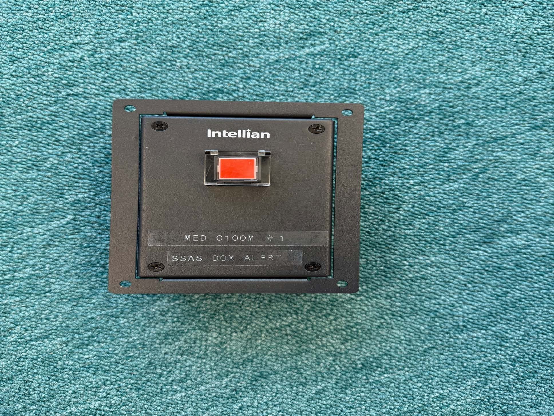
XXZ-INTC200GS
Feb 05, 2026Iridium Certus satellite GMDSS terminal with WLAN
Equipment Class
TNB - Licensed Non-Broadcast Station TransmitterXXZ-OW10HX
Jun 26, 2024Compact User Terminal Antenna
Equipment Class
TNB - Licensed Non-Broadcast Station Transmitter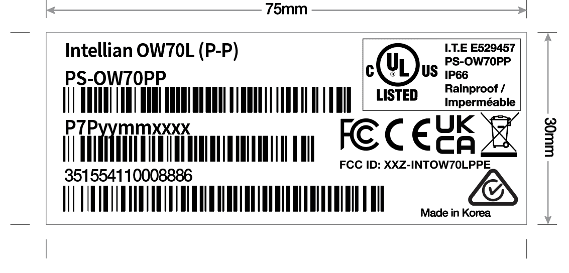
XXZ-INTOW70LPPE
Dec 03, 2023OW70L (P-P)
Equipment Class
TNB - Licensed Non-Broadcast Station TransmitterXXZ-INTFB500
Oct 25, 2022Marine Fleet Broadband
Equipment Class
TNB - Licensed Non-Broadcast Station Transmitter
XXZ-INTOW70LDAC
Jul 28, 2021OneWeb OW70L UT (12dB/K)
Equipment Class
TNB - Licensed Non-Broadcast Station Transmitter