XYANUM8Wrist Worn GSM Tracking Device
Lok8u Limited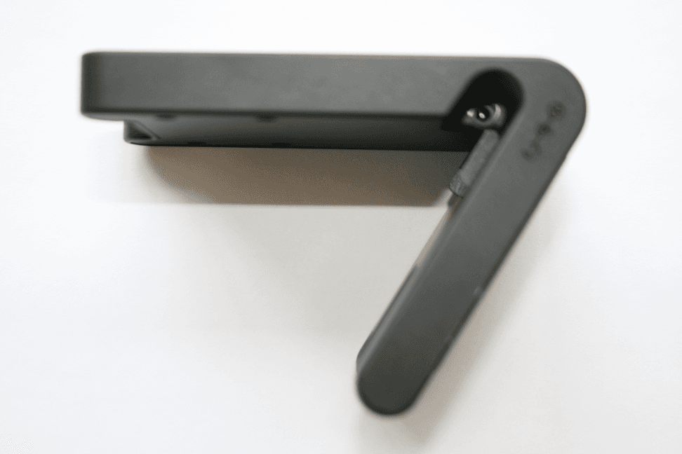
Click to zoom
Application Details
- Equipment Class
- PCT - PCS Licensed Transmitter worn on body
- Date of Grant
- Feb 01, 2010
- Application Purpose
- Original Equipment
- Date of Application
- Feb 01, 2010
- Equipment Note
- Wrist Worn GSM Tracking Device
- Frequency Range
- 1850.20000000 - 1909.80000000
- Company
- Lok8u Limited
- Country
- United Kingdom
Documents & Files
Document Text
Text extracted from the exhibit documents filed with the FCC. Open a document above to read the original.
Users Manual
User Guide Introduction Thank you for purchasing nu•m8; the world‟s first location device specifically designed to be worn by children. It is my hope that nu•m8 will make parents feel more comfortable in allowing their children to play un-supervised, so that “kids can be kids” and enjoy the benefits of being free to interact with their peers through unstructured play. I know, like you, that the social environment in which our children are growing up can, at times, be perilous and therefore we all want to make sure our children are safe and free from harm. nu•m8 does not make the environment safer but will allow you to know where your children are, control the areas in which they play and be the first to know if they are at risk. Please read this simple user guide carefully to get the best out of your nu•m8 and remember it is an aid to parental care and control; it must not be regarded as a substitute. As a parent myself, it was the urge to keep my children safe, whilst letting them enjoy the freedom of childhood that I enjoyed that spurred the development of nu•m8. I know that it will live up to your expectations but if there are any suggestions that you think would be sensible to incorporate I will give them my full attention. I can be contacted at [email protected]. S.K.Salmon Chief Executive 1 Contents Getting started ..................................................................................................................... 3 Start-up ................................................................................................................................ 6 Time ..................................................................................................................................... 8 Using the Customer Portal ................................................................................................... 9 Where are you request ...................................................................................................... 12 Maximise map .................................................................................................................... 17 Set, apply and edit a „Safe Zone‟ ....................................................................................... 19 Removing nu•m8 without triggering an alert ...................................................................... 29 Live Track .......................................................................................................................... 32 Alerts.................................................................................................................................. 34 Home Zone ........................................................................................................................ 37 My details........................................................................................................................... 38 Calendar ............................................................................................................................ 39 Waterproof ......................................................................................................................... 40 Certification ........................................................................................................................ 41 Product Information ........................................................................................................... 43 APPENDIX ONE (i) ............................................................................................................ 45 APPENDIX TWO (ii) .......................................................................................................... 46 2 Getting started Remove nu•m8 from its packaging and place it on charge using the supplied desk top charger for a full 8 hours before use. The red LED will illuminate whilst nu•m8 is charging. This will be replaced by the green LED illuminating when nu•m8 is fully charged. The green LED light may illuminate faster than quoted above but we still advise that you charge it the full 8 hours to ensure that the battery is fully topped up. Whilst there may be some residual charge from manufacture it is not safe to use nu-m8 until it is fully charged, as described above. Please go to www.lok8u.com/uk/portal and click “register me” to register your nu•m8 and enable the incorporated sim card to be activated. Doing this will allow nu•m8 to broadcast its location to the Lok8u pinpoint server infrastructure whilst in use. You will receive an email confirming that the sim card has been activated, together with the phone number of your nu•m8, within a maximum of 24 hours from registration. It will then be ready for use. Log-in page 3 Device details To complete the registration process you will need:- the serial number of your nu•m8, (found on the base of the packaging) gift certificate number (if applicable) a valid debit or credit card registered at your address the telephone number of the mobile phone, and email address that you want to receive alerts to as primary contact A digital photograph of your child, or other image, if you want to upload it to your part of the customer portal, maximum size 200kb Select the required subscription tariff (to select the subscription that is most appropriate for your planned use of Nu•m8. Please refer to http://www.lok8u.com/uk/order-now for the available options.) It can take up to 24 hours to activate the sim. Once this has been completed you will receive an email confirming that the sim card has been activated together with the phone number of your nu-m8. Once you have received this email you can then activate nu•m8. To do this you MUST switch it on by inserting the strap in to the housing whilst the watch is off the wrist and click the re-set switch with the tool provided in the charger base. (The re- set switch is found on the back plate next to the gold charging pins). nu•m8 will then go through its ac…
Text truncated - open the document above for the full version.
Cover Letter(s)
:-::::* -- t"tffi ;16*rtoENrrALrrY REeuESr Federal Communication Commission Equipment Authorization Divisioru Application Processing Branch 7435 Oakland Mills Road Columbia, MD 2L048 February 75,2007 TO WHOM IT MAY CONCERN Pursuant to Paragraphs $0.457 and 0.459 of the Commissionl's Rules (a7 C.F.R.) and Section S552(bX4) of the Freedom of hrformation Act, WAWCAM S.A. requests confidentiality for the following products: FCC ID Number Product Title/Model O9EWMPI00 Wireless Miuaprocessor WMP700 For the product stated above, we request that the following information be held confidential: '1,. Circuit diagrams, BOM, and PCBs submitted as Equipment Authorizatton Electronic Filing attachment: "schematics". 2. Block diagram submitted as Equipment Authorization Electronic Filing attachment "blockdia grarn" . 3. Operational description submitted as Equipment Authorization Electronic Filing attachment " operational description" The above exhibits contain WAWCOM S. trade secrets and proprietary information that could be of benefit to our competitors regarding the design of our mobile handset. This material is not customarily available to the general public and we request that it be withheld from public inspection. If you have arty questions, please feel free to contact me at the address shown below. Sincerely, Name: D. CYNE Company: WAVECOM S.A. Address:3 esplanade du Foncet 92442 Issy les Moulineaux FRANCE Phone: + 33 (0)1 4629 429\ Email: [email protected] WAVECOM S.A 3, esplanade du Foncet, 92442 lssy-les-Moulineaux - France Tel : +33 (0)l 46 29 08 00 Fax: +33 (0)1 46 29 08 08 ww.wavecom.com SA au caoital de 15 531 813 euros - R.C.S Nanterre B 391 838 042 WAVECOM @ 2006. All rights reserved ffi ",au SG!
External Photos
Lok8u NuM8 – External Product Photographs
Internal Photos
Lok8u NuM8 - Internal Product Photographs
Operational Description
Operational Description – Lok8u NuM8 NuM8 is a wrist worn child tracking device. It utilises GPS and GSM technology, both of which are modular within the device. GPS – eRide miniRide Opus one 32 channel GPS/AGPS receiver Module. This is used to locate the device. GSM – Wavecom WMP100 Quad band modem. The antenna for GPS is a Sarantel Geo helix design. GSM antenna is our own quad band design. The device can be woken out of idle state by either receiving a GPRS data packet or a SMS. Modes In all modes the device boots up onto the GSM network and goes to an idle mode to conserve battery life. Idle Mode – This is used if the device is not needed to be located, it will stay in this mode until the battery has been consumed or turned off. In idle mode the device operates in GPRS packet mode only, this allows the device to stay registered with the network and the carrier does not remain on. WRU – This allows the device to be located, on receiving the command it will carry out a GPS lookup and report back its position to the server and then return to idle mode. When sending a position we are sending 21 bytes of data which fits within a single GPRS time slot of 570 microseconds. Live Track – In live track the device can be configured to automatically return a position every 2, 5, 10, 15 or 30 minutes. The data transmitted is exactly the same as a WRU request, except the device carries it out automatically. The time period between position lookup the device returns to idle mode. Safe Zone – This mode checks that the device is within a pre-determined area. It holds the area in its own memory and compares this to the position lookup it carries out. If the position is within the pre-determined zone then the position is not sent to the server. If however it is outside of this zone then the position is sent to the server the same way as the WRU request. It can be configured to check its position every 2, 5, 10, 15 or 30 minutes. The time period between position lookup the device returns to idle mode.
Parts List/Tune Up Info
2008 Sierra Wireless Inc. This document contains information which is proprietary and confidential to Sierra Wireless Inc. Disclosure to persons other than the officers, employees, agents, or subcontractors of the Company or licensee of this document without the prior written permission of Sierra Wireless Inc. is strictly prohibited. WMP100 Wireless Modem Tune up procedure Document #: Revision: 1.1 SIERRA WIRELESS INC. Document #: Revision: 1.1 Page 2 of 3 2008 Sierra Wireless Inc. The contents of this page are subject to the confidentiality information on page one. The WMP100 wireless modem is equipped with a GSM/GPRS transceiver radio. The radio meets the requirements of the 3rd Generation Partnership Project Technical Specification Group; Mobile Station (MS) conformance specification; Part 1: Conformance specification “3GPP TS 51.0101” The WMP100 calibration process comprises of a suite of Radio Frequency (RF) transmitter, receiver, and modulation tests that define tuning calibration values which are saved inside of each Device Under Test (DUT). Each supported band is calibrated separately. Calibration test equipment consists of an RF signal generator, power meter and a radio communication test set that combines both. The calibration process is conducted in a shielded enclosure which prevents external RF signals from interfering or contributing to DUT RF measurements. All transmitter power measurements made by the instruments report the power at the DUT's RF connector. A process known as RF Normalization measures both the RF cable loss and power meter inaccuracy values in order to calculate the precise power at the DUT connector. The Calibration process is automated, with a host PC controlling both the test equipment and DUT. The PC's calibration program insures that the tuning parameters found are reasonable by applying limits to them, and by running calibration performance tests where the DUT employs its internal calibration values. Upon successful completion of all tests and conditional upon finding all results within limits, the DUT is confirmed ready for use. The range of allowable operating power levels are defined as per the tables below Range of operating RF power levels for GSM 1900 (PCS) Power Control Level Signal Tolerances dBm Normal Extreme 0 30 +/-2 dB +/-2.5 dB 1 28 +/-3 dB +/-4 dB 2 26 +/-3 dB +/-4 dB 3 24 +/-3 dB +/-4 dB 4 22 +/-3 dB +/-4 dB 5 20 +/-3 dB +/-4 dB 6 18 +/-3 dB +/-4 dB 7 16 +/-3 dB +/-4 dB 8 14 +/-3 dB +/-4 dB 9 12 +/-4 dB +/-5 dB 10 10 +/-4 dB +/-5 dB 11 8 +/-4 dB +/-5 dB 12 6 +/-4 dB +/-5 dB 13 4 +/-4 dB +/-5 dB 14 2 +/-5 dB +/-6 dB 15 0 +/-5 dB +/-6 dB SIERRA WIRELESS INC. Document #: Revision: 1.1 Page 3 of 3 2008 Sierra Wireless Inc. The contents of this page are subject to the confidentiality information on page one. Range of operating RF power levels for GSM 850 Power Control Level Signal Tolerances dBm Normal Extreme 5 33 +/-2 dB +/-2.5 dB 6 31 +/-3 dB +/-4 dB 7 29 +/-3 dB +/-4 dB 8 27 +/-3 dB +/-4 dB 9 25 +/-3 dB +/-4 dB 10 23 +/-3 dB +/-4 dB 11 21 +/-3 dB +/-4 dB 12 19 +/-3 dB +/-4 dB 13 17 +/-3 dB +/-4 dB 14 15 +/-3 dB +/-4 dB 15 13 +/-3 dB +/-4 dB 16 11 +/-5 dB +/-6 dB 17 9 +/-5 dB +/-6 dB 18 7 +/-5 dB +/-6 dB 19 5 +/-5 dB +/-6 dB
RF Exposure Info
Summary of KDB information: (Tracking Number: 189479) FCC ID: XYANUM8 The Num8 Device is a wrist-worn tracking device that supports only GPRS and has no support for voice. The device transmits user location information where the transactions are very short. During the transaction 21 bytes of data are transmitted over the GPRS network. The device only operates with the wrist strap/bracelet attached. The device uses only one transmitter which is a Wavecom WMP100 module with FCC ID: O9EWMP100. Consideration for exemption: The Num8 device has two mode of operation: LT (live track) – where the device is put into this function so it report back its position every 2, 5, 10, 15 or 30 minutes. SF (safe zone) – where an area can be designated that the device is allowed to be in and it will check its position every 2, 5, 10, 15 or 30 minutes. If the position is outside of the pre- determined zone than an alert will be sent. The device has no conducted ports therefore the conducted average power of the Wavecom WMP100 module in the FCC grant (33 dBm / 2 watts) is used. The minimum transaction time was < 1 second as only 21 bytes is transmitted and fits within a single GPRS time slot of 570 microseconds. For the purpose of this KDB the worst case repetition time of 2 minutes / 120 seconds was used, as this is the shortest time in which the Num8 device is idle for. The NuM8 device creates a pdp context connection to the NuM8 Server at boot up; this connection allows the sending of UDP data from the device, the device sends no data during idle. To enter idle we sent AT+W32K=1. If Num8 is placed into its worst case mode which is 120 second live track mode, the device sends data for a single GPRS Time slot every 120 seconds. This is performed by the WMP100 under its standard pdp context connection handling system. In the 2 minute Live Track mode, the device goes into idle mode for 120 seconds between transmissions. At this point a transmitting of 21 bytes is sent which fits within a single GPRS time slot of 570 microseconds, as stated. The device stays registered with the network and the carrier does not remain on. Therefore: 1 single slot is used in the entire 120 second period or 1 slot in 210526 slots. Duty factor = 570microseconds / 120 second = 0.0000047 Average Power in transmission = 2watts (worst-case average power from Wavecom WMP100 module) * 0.0000047 (Duty factor) = 0.0000094watts Idle mode does not disable the module. Disabling the module would require it to register on the network every time we need to send data and would cause more overhead than is required. When idle the device is still registered on the network but is not transmitting data at all. The 2 minute Live Track is the harshest mode for the device. Because of the extremely low duty factor and the source-based time-averaged conducted output is less than 60/f, SAR testing is excluded for this device.
Test Report
CETECOM ICT Services GmbH Untertürkheimer Str. 6-10, 66117 Saarbruecken Phone: +49 (0) 681 598-0 Fax: -9075 RSC-Laboratory Phone: +49 (0) 681 598-0 Fax: -9075 Test report no.: 4-2445-01-04/07 Date: 2007-03-03 Page 1 of 64 Recognized by the Federal Communications Commission Anechoic chamber registration no.: 90462 (FCC) Anechoic chamber registration no.: IC 3463A-1 TCB ID: DE 0001 Accredited by the German Accreditation Council DAR–Registration Number DAT-P-176/94-D1 Independent ETSI compliance test house ETSI Accredited Bluetooth ® Test Facility (BQTF) Test report No. : 4-2445-01-04/07 Applicant : Wavecom S.A. Type : WMP100 Test Standard : FCC Part 22, 24 RSS-132, -133 FCC ID : 09EWMP100 Certification No. IC : 3651C-WMP100 The Bluetooth word mark and logos are owned by the Bluetooth SIG, Inc. and any use of such marks by Cetecom ICT is under license CETECOM ICT Services GmbH Untertürkheimer Str. 6-10, 66117 Saarbruecken Phone: +49 (0) 681 598-0 Fax: -9075 RSC-Laboratory Phone: +49 (0) 681 598-0 Fax: -9075 Test report No.: 4-2445-01-04/07 Date: 2007-03-03 Page 2 of 64 Table of contents 1 GENERAL INFORMATION...................................................................................................................................................3 1.1. ADMINISTRATIVE DATA OF THE TEST FACILITY..................................................................................................................3 1.1.1 Identification of the testing laboratory......................................................................................................................3 1.2. NOTES........................................................................................................................................................................................3 1.3 DETAILS OF APPLICANT..........................................................................................................................................................4 1.4 APPLICATION DETAILS...........................................................................................................................................................4 1.5 ADDITIONAL EUT INFORMATION FOR IC CANADA (APPENDIX 2)...................................................................................5 1.6 TEST SETUP..............................................................................................................................................................................6 1.7 TEST STANDARDS....................................................................................................................................................................6 2 STATEMENT OF COMPLIANCE.........................................................................................................................................7 2.1 SUMMARY OF MEASUREMENT RESULTS..............................................................................................................................7 2.1.1 PCS 1900.........................................................................................................................................................................7 2.1.2 GSM 850..........................................................................................................................................................................7 3 MEASUREMENTS AND RESULTS......................................................................................................................................8 3.1 PART PCS 1900......................................................................................................................................................................8 3.1.1 RF Power Output...........................................................................................................................................................8 3.1.2 Frequency Stability......................................................................................................................................................12 3.1.3 Radiated Emissions.....................................................................................................................................................15 3.1.4 Receiver Radiated Emissions.....................................................................................................................................21 3.1.5 Conducted Spurious Emissions.................................................................................................................................24 3.1.6 Block Edge Compliance..............................................................................................................................................27 3.1.7 Occupied Bandwidth...................................................................................................................................................29 3.2 PART GSM 850....................................................................................................................................................................33 3.2.1 RF Power Output.........................................................................................................................................................33 3.2.2 Frequency Stability......................................................................................................................................................36 3.2.3 Radiated Emissions.....................................................................................................................................................39 3.2.4 Receiver Radiated Emissions.....................................................................................................................................50 3.2.5 Conducted Spurious Emissions.................................................................................................................................53 3.2.6 Block Edge Complian…
Text truncated - open the document above for the full version.
Test Report
CETECOM ICT Services GmbH Untertürkheimer Str. 6-10, 66117 Saarbruecken Phone: +49 (0) 681 598-0 Fax: -9075 RSC-Laboratory Phone: +49 (0) 681 598-0 Fax: -9075 Annex to Test report no.: 4-2445-01-04/07 Date: 2007-03-03 Page 1 of 22 \\ut55\4_PROJEKTE\07\2445_1\Task4(MCP)\Annex 4-2445-01-04_07v2.doc Recognized by the Federal Communications Commission Anechoic chamber registration no.: 90462 (FCC) Anechoic chamber registration no.: IC 3463A-1 TCB ID: DE 0001 Accredited by the German Accreditation Council DAR–Registration Number DAT-P-176/94-D1 Independent ETSI compliance test house ETSI Accredited Bluetooth ® Test Facility (BQTF) Annex to Test report no. : 4-2445-01-04/07 Applicant : Wavecom Test Standard : FCC Part 15 / RSS-210 The Bluetooth word mark and logos are owned by the Bluetooth SIG, Inc. and any use of such marks by Cetecom ICT is under license CETECOM ICT Services GmbH Untertürkheimer Str. 6-10, 66117 Saarbruecken Phone: +49 (0) 681 598-0 Fax: -9075 RSC-Laboratory Phone: +49 (0) 681 598-0 Fax: -9075 Annex to Test report no.: 4-2445-01-04/07 Date: 2007-03-03 Page 2 of 22 Table of contents 1 GENERAL INFORMATION ......................................................................................................................................... 3 1.1. ADMINISTRATIVE DATA OF THE TEST FACILITY........................................................................................................... 3 1.1.1 Identification of the testing laboratory ............................................................................................................... 3 1.2. NOTES......................................................................................................................................................................... 3 1.3 DETAILS OF APPLICANT............................................................................................................................................... 4 1.4 APPLICATION DETAILS................................................................................................................................................ 4 1.5 TEST SET-UP DESCRIPTION.......................................................................................................................................... 5 1.6 TEST SPECIFICATIONS.................................................................................................................................................. 5 2 STATEMENT OF COMPLIANCE ................................................................................................................................ 6 2.1 SUMMARY OF MEASUREMENT RESULTS...................................................................................................................... 6 2.1.1 CFR 47 Part 15 Radio frequency devices ........................................................................................................... 6 3 MEASUREMENTS AND RESULTS ............................................................................................................................. 7 4 ANNEX A: FCC PART 15 SUBPART B........................................................................................................................ 8 4.1 CONDUCTED LIMITS.................................................................................................................................................... 8 4.2 RECEIVER SPURIOUS EMISSION RADIATED (IDLE MODE) ............................................................................................ 12 5 USED TESTEQUIPMENT ............................................................................................................................................ 15 6 ANNEX B: PHOTOGRAPHS OF TEST SITE ........................................................................................................... 18 7 ANNEX C: PHOTOGRAPHS OF THE EQUIPMENT.............................................................................................. 20 CETECOM ICT Services GmbH Untertürkheimer Str. 6-10, 66117 Saarbruecken Phone: +49 (0) 681 598-0 Fax: -9075 RSC-Laboratory Phone: +49 (0) 681 598-0 Fax: -9075 Annex to Test report no.: 4-2445-01-04/07 Date: 2007-03-03 Page 3 of 22 1 General information 1.1. Administrative data of the test facility 1.1.1 Identification of the testing laboratory Company name: Cetecom ICT Services GmbH Address: Untertürkheimerstr. 6-10 D-66117 Saarbruecken Germany Laboratory accreditation: DAR-Registration No. DAT-P-176/94-D1 Bluetooth Qualification Test Facility (BQTF) Federal Communications Commission (FCC) Identification/Registration No : 90462 Responsible for testing laboratory: H. Ames Phone: +49 681 598 0 Fax: +49 681 598 9075 email: [email protected] 1.2. Notes The test results of this test report relate exclusively to the test item specified in 1.5. The CETECOM ICT Services GmbH does not assume responsibility for any conclusions and generalizations drawn from the test results with regard to other specimens or samples of the type of the equipment represented by the test item. The test report may only be reproduced or published in full. Reproduction or publication of extracts from the report requires the prior written approval of the CETECOM ICT Services GmbH. .................................................................................. Responsible for testing (D. Gilmann) .................................................................................. Responsible for laboratory (H. Ames) CETECOM ICT Services GmbH Untertürkheimer Str. 6-10, 66117 Saarbruecken Phone: +49 (0) 681 598-0 Fax: -9075 RSC-Laboratory Phone: +49 (0) 681 598-0 Fax: -9075 Annex to Test report no.: 4-2445-01-04/07 Date: 2007-03-03 Page 4 of 22 1.3 Details of Applicant Name : Wavecom Address : 3 esplanade du Foncet City : 92442 Issy - Les - Moulineaux Cedex Country : France Phone : + 33 (0) 1 46 29 08 00 Fax : + 33 (0) 1 46 29 08 08 Contact : Mr. Raphael Law-Boum Phone : + 33 (0) 1 46 29 41 91 Fax : + …
Text truncated - open the document above for the full version.
Test Report
TEST REPORT FROM RFI GLOBAL SERVICES LTD Test of: Num8 To: FCC Part 22.913(a) and FCC Part 24.232 Test Report Serial No: RFI/RPT2/RP75594JD01A Version 2 Supersedes All Previous Versions This Test Report Is Issued Under The Authority Of Brian Watson, Operations Director: Checked By: Nigel Davison Signature: Date of Issue: 02 February 2010 This report is issued in Adobe Acrobat portable document format (PDF). It is only a valid copy of the report if it is being viewed in PDF format with the following security options not allowed: Changing the document, Selecting text and graphics, Adding or changing notes and form fields. This report may not be reproduced other than in full, except with the prior written approval of RFI Global Services Ltd. The results in this report apply only to the sample(s) tested. TEST REPORT SERIAL NO: RFI/RPT2/RP75594JD01A ISSUE DATE: 02 FEBRUARY 2010 Page 2 of 12 RFI Global Services Ltd This page has been left intentionally blank. TEST REPORT SERIAL NO: RFI/RPT2/RP75594JD01A ISSUE DATE: 02 FEBRUARY 2010 RFI Global Services Ltd Page 3 of 12 Table of Contents 1. Customer Information .................................................................................................................. 4 2. Summary of Testing ..................................................................................................................... 5 3. Equipment Under Test (EUT) ....................................................................................................... 6 4. Operation and Monitoring of the EUT during Testing ............................................................... 7 5. Measurements, Examinations and Derived Results .................................................................. 8 6. Measurement Uncertainty .......................................................................................................... 11 Appendix 1. Test Equipment Used ..............................................................................................…
Text truncated - open the document above for the full version.
Contact Information
Applicant
Steven K Salmon
Technical Contact
Test Firm
UL VS LtdDarren Rust
Technical Specifications
| # | Rule Parts | Frequency Range | Power Output | Emission | Tolerance |
|---|---|---|---|---|---|
| 2 | 24E | 1.85 GHz - 1.91 GHz | 260.00 mW | 300KGXW | 51 Hz |
Other Applications from Lok8u Limited
XYALOK8UFRMBS
Dec 19, 2011FREEDOM-MBS
Equipment Class
DSC - Part 15 Security/Remote Control Transmitter