XZMACTIVE-XRadar Target Enhancer
Aquamate Products Limited
Click to zoom
Application Details
- Equipment Class
- SRT - Radar Transponder
- Date of Grant
- Jan 20, 2010
- Application Purpose
- Original Equipment
- Date of Application
- Dec 07, 2009
- Equipment Note
- Radar Target Enhancer
- Frequency Range
- 9300.00000000 - 9500.00000000
- Company
- Aquamate Products Limited
- Country
- United Kingdom
Documents & Files
Document Text
Text extracted from the exhibit documents filed with the FCC. Open a document above to read the original.
Users Manual
...asignificantadvanceinmarinesafety! Radar Target Enhancer Radar Target Enhancer Ac t i v e-X- B a n dAc t i v e-X- B a n d Manufactured by Echomax Products in the UK PO Box 6032, Dunmow CM6 3AS, UK. Email: [email protected] www.echomax.co.uk Tel: 00 44 (0)1371 830216 Fax: 831733 OPERATIONMANUAL Echomax Active-X-Band RTE shown with optional Stainless base fitting Radar Target Enhancer Radar Target Enhancer Ac t i v e-X- B a n dAc t i v e-X- B a n d GENERAL INTRODUCTION The Echomax Active-X Radar Target Enhancer (RTE) is designed to respond to interrogating X band radar (9.3 – 9.5GHz) by receiving a transmitted pulse and amplifying the pulse and re-transmitting the pulse back to the radar at the same frequency with minimum delay, thereby improving the radar detection range and visibility of small targets. It will not enhance significantly vessels with large radar cross section. The RTE is primarily intended for small vessels with no radar fitted and typically should enhance the RCS (radar cross section) of vessels up to 25M in length. For small craft/rigid inflatables improvements will start to be seen at around 1-2 miles extending to 8-10 miles or more depending on prevailing conditions. The response of the RTE will vary according to range, RTE and radar height above sea level, radar power and condition. Poor weather, sea state and precipitation will greatly reduce the response IMPORTANT The fitting of the Echomax Active-X does not exclude you from exercising safe navigational judgement for your vessel under the International Regulations for the Prevention of Collisions at Sea and to keep a proper look out at all times LICENSING REQUIREMENTS Many countries and administrations require a ships radio license or modification of your existing ships radio licence before Active-X can be used for maritime use. Contact your local administration for details. ECHOMAX ACTIVE-X COMPONENTS, CONSTRUCTION, use and installation If you are not able to safely install the unit yourself you are advised to seek the services of a competent person or company to install the RTE. COMPONENTS Echomax Active-X mast head radome fitted with 24 meters of 2 core cable Control box Operation manual RADOME FITTING The antenna has provisions in the base for a 1 inch - 14 NF female thread mast fitting or deck mount bracket. Plastic mounts should not be used. To ensure a permanent fixing ‘LOCTITE’ or PTFE or plumbers tape should be used and the RTE must be screwed down tightly. Care must be taken to ensure that as the RTE is tightened on the base the cable is allowed to turn freely. For mast fitting the radome must be fitted verticallly as high as possible. The recieve/ transmit antennas positioned 70mm from the base of the radome and have a clear 360 degree azimuth. It should be fitted at least 6 inches/150mm from the mast on the offset bracket. It should not be fitted on a back stay or where its vision is obscured or is close to any metal object otherwise performance could be significantly impaired. The radome unit must never be painted as this will seriously impair performance. The radome must not be fitted in or close to the vessels radar transmitting ECHOMAX CONTROL BOX, use and wiring instructions The control box must be fitted internally as it is not waterproof and can be wired from the base or back as required. A 12v fused or circuit breaker supply of 3-5A is required. The control box has a triple alarm facility. Once the red power switch is turned on the unit is in the quiescent mode and will consume up to 15mA. When interrogated by a radar the green LED light will flash every 2.4 seconds. If the flash lengthens then this indicates that more than one radar is painting the antenna. If painted by a high speed radar which rotates every 1.5 seconds then the LED light will flash quicker. Turning on the green switch will mobilize the i n t e rnal buzzer, which is set to actuate for appro x i m a t e l y half a second intervals. The control box also has facilities for a 8A external volt free alarm. The control box has an externally replaceable 0.5A fuse and is surge and cross polarity protected. beam width of 23 degrees as this may seriously damage the PCB. The RTE should be fitted below or preferably above the radar. It is possible to shorten or extend the cable by a further 25 meters without affecting the p e rf o rm a n c eusing extension cable rated at 3A at 300V. RTECONNECTIONS The diagrams show the correct wiring installation PERFORMANCE CHECK As the RCS of your vessel may exceed the RCS of the RTE, the trial is best carried out at 0.5 nm as the target can be easily identified. The range should then be increased at intervals of 0.5 nm and the RTE switched on and off noting the change in response. As the range increases the bare target will not be seen and whilst moving the RTE is left on so that the test target can be seen at all times. This is important in busy waters to avoid confusion with other vessels. If the target is lost it can be acquired by turning the RTE on and off and watching the display for change in target response. In normal weather and sea conditions, with RTE and interrogating radar mounted at four meters above sea level should respond on the radar screen as shown below. If the mounting heights, including that of the interrogating radar vary so will the response due to curvature of the earth. These figures are for guidance only and should not be relied upon. 2KW radar up to 4 nm : 5KW radar up to 10 nm : 10- 25KW radar up to 15-20 nm FAULT FINDING CHART No Red LED light when red switch Check fuse or circuit breaker is turned on Check polarity of wiring Check power supply at control box Damaged cable or wrong connection Unit switched on and continuous green Local radar on, or radar operating moored nearby (<15M) LED light shows, in harbour or when Moored close to large metal object saturating RTE Check polarity of radome wiring Being actuated by ships own radar – turn off radar and if necessary r…
Text truncated - open the document above for the full version.
Attestation Statements
FAO: Federal Communications Commission Authorisation and Evaluation Division 7435 Oakland Mills Rd Columbia MD 21046 6 th December 2009 FCC ID XZMActive-X Confirmation Number EA926497 Dear Sir, Please find the submissions for FCC approval of the Echomax Active-X X-band Radar Target Enhancer (RTE) uploaded to the FCC OET website. An active radar reflector, commonly known as an RTE, provides an enhanced radar return to better ensure detection of small vessels. An RTE consists of a receive antenna, RF amplifier and a transmit antenna. An RTE does not transpond or generate a transmission; it purely re-transmits an amplified version of the received radar signal. The International Maritime Organisation SOLAS regulations require that all vessels under 150 gross tonnage and if practicable, carry a radar reflector, or other means, to enable detection by ships navigating by radar. (Chapter V, Regulation 19.2.1.7). The device referred to here meets this requirement for enhancing target definition on shipborne marine radars operating in the X band. In consultation with Tim Maguire 1 of the Wireless Telecommunications Bureau we understand that this device is covered by CFR47 part 80.375(d) for radio- determination devices used in the 9300MHz to 9500MHz band (X band). In this email, he also recommends providing test results to show compliance with ITU- R M.1176 and IMO Resolution MSC.164(78). To ensure that this device meets the above mentioned resolution and recommendations, it has been tested for X-band performance in accordance 1 In email dated 8 th September 2009 between Tim Maguire and independent consultant, Dave Walsh. with ISO8279-2 ‘Ships and Marine Technology - Marine radar reflectors - Part 2: Active type’. In Europe the device has been given a positive notified body opinion (under the EU R&TTE directive). A copy of this opinion is attached. Echomax is the brand name of Aquamate Products Limited, PO Box 6032, Dunmow, Essex, CM6 3AS, United Kingdom. The Echomax Active-X RTE was designed by Coverise Limited on behalf of Aquamate Products Ltd. I hereby confirm that the Echomax Active-X Radar Target Enhancer meets the International Recommendation ITU-R M.1176 for such devices and has been tested in accordance with the International Standard. The device is compliant with CFR47 part 80.375(d) Yours faithfully David Sheekey Product and Approvals Manager Coverise Ltd
Cover Letter(s)
Federal Communications Commission 445 12th Street, SW Washington DC 20554 United States of America 3 rd December 2009 Request for Confidentiality We would respectfully request that the items listed below remain confidential and are not made available for public inspection. The information contains commercially sensitive information which is the property of Coverise Ltd Operational Description Schematics Parts Lists I thank you in your cooperation in this matter. Yours truly David Sheekey Product and Approval Manager Coverise Limited
External Photos
External Photos Figure 1: Echomaster Active-X Side View, showing product label. Figure 2: Active-X Bottom View Figure 3: Active-X Top View
ID Label/Location Info
FCC ID Label and Location The Product identity label will carry the FCC ID as shown. This label is permanently affixed to the body of the RTE as shown below
ID Label/Location Info
FCC ID Label and Location - Revised Revised label in accordance with 2.925(a). The colon after ‘FCC ID’ has been added and all lettering is now in upper case as requested in correspondence number 38490. The Product identity label will carry the FCC ID as shown. This label is permanently affixed to the body of the RTE as shown below
Internal Photos
Internal Photos Figure 1: Active-X PCB Assembly showing antennas Figure 2: Active X PCB Assembly Top Side Figure 3: Active X PCB Assembly Bottom Side: RF circuitry Note: this side covered in overall screening can, removed for this photo.
RF Exposure Info
Human Exposure to Electromagnetic Fields This document demonstrates that the Echomax Active-X Radar Target Enhancer is in compliance with both US and EU requirements for protection of the general public from exposure to electromagnetic fields. In the US regulation 47CFR chapter 1.1310 1 specifies that in the band 1500 – 100,000MHz the exposure limit is 1mW/cm 2 . In the EU, Directive 1999/519/EC 2 Annex III; Table 2 3 gives a limit of 10W/m 2 in the frequency range 2-300GHz. (Note: converting centimetres to metres gives 1mW/cm 2 = 10W/m 2 ) From the test results in Coverise test report OPP001; Peak Output Power = 26.4dBm Antenna gain = 5.8dBi ∴EIRP = 32.2dBm Hence P = 1659.6mW S= 1mW/cm 2 Distance at which the power density meets the 1mW/cm 2 limit is given by r = √P/(4 x π x S) r = 11.5cms (= 4.5inches) Therefore the Active-X meets the requirements for exposure to radiated electromagnetic fields at a worst case distance of 11.5cms from the transmitting antenna in both the USA and Europe. Note: This calculation is based on the continuous peak output power. In practice the RTE will only be illuminated for a small percentage of the time, so the safe distance will be significantly reduced. David Sheekey 4 th December 2009 Coverise Ltd. 1 1.1310 Radiofrequency radiation exposure limits 2 Council Recommendation on the limitation of exposure of the general public to electromagnetic fields(0Hz to 300GHz) 3 Reference levels for electric, magnetic and electromagnetic fields (0Hz to 300GHz,unperturbed rms values)
Test Report
Test Report to CFR47 Part 80 ISO8729-2:2009 Echomax Active-X Radar Target Enhancer 27th November 2009 OPERATIONAL TEST REPORT Product: Echomax Active-X Radar Target Enhancer Page: 2 of 29 Serial No: PP016 Date: 27/07/09 Report compiled by: David Sheekey Test Report: OPP002 This report cannot be reproduced, except in full, without the prior written permission of Coverise Ltd. 1. INTRODUCTION..................................................................................................................................4 1.1. PRODUCT DESCRIPTION.....................................................................................................................4 1.2. TEST LOCATIONS................................................................................................................................5 2. TEST SUMMARY...................................................................................................................................7 2.1. TEST RESULT......................................................................................................................................7 2.2. TEST ACKNOWLEDGMENT..................................................................................................................7 3. TEST EQUIPMENT USED.................................................................................................................8 4. OPERATION TEST RESULTS..........................................................................................................9 4.1. STATED PERFORMANCE LEVEL (SPL)...............................................................................................9 4.1.1. Test Method............................................................................................................................9 4.1.2. Equipment Used..................................................................................................................10 4.1.3. Results....................................................................................................................................10 4.2. TIME DELAY TEST.............................................................................................................................10 4.2.1. Test Method..........................................................................................................................10 4.2.2. Equipment Used..................................................................................................................10 4.2.3. Results....................................................................................................................................11 4.3. STABILITY TEST................................................................................................................................11 4.3.1. Test Method..........................................................................................................................11 4.3.2. Equipment Used..................................................................................................................11 4.3.3. Results....................................................................................................................................11 4.4. INDUCED STABILITY TEST...............................................................................................................11 4.4.1. Test Method..........................................................................................................................11 4.4.2. Equipment Used..................................................................................................................12 4.4.3. Results....................................................................................................................................12 4.5. POWER EMISSION TEST...................................................................................................................12 4.5.1. Test Method..........................................................................................................................12 4.5.2. Equipment Used..................................................................................................................12 4.5.3. Results....................................................................................................................................12 4.6. SATURATED POWER TEST................................................................................................................13 OPERATIONAL TEST REPORT Product: Echomax Active-X Radar Target Enhancer Page: 3 of 29 Serial No: PP016 Date: 27/07/09 Report compiled by: David Sheekey Test Report: OPP002 This report cannot be reproduced, except in full, without the prior written permission of Coverise Ltd. 4.6.1. Test Method..........................................................................................................................13 4.6.2. Equipment Used..................................................................................................................13 4.6.3. Results....................................................................................................................................13 4.7. TOLERANCE TO RADAR IN CLOSE PROXIMITY................................................................................13 4.7.1. Test Method..........................................................................................................................13 4.7.2. Equipment Used..................................................................................................................14 4.7.3. Results....................................................................................................................................14 4.8. PULSE LENGTH CHECK.....................................................................................................................14 4.8.1. Test Method...............................................…
Text truncated - open the document above for the full version.
Test Report
Report For Testing To IEC60945 For EMC Only Echomax Active-X Radar Target Enhancer 5 th June 2009 EMC TEST REPORT Product: Echomax Active-X Radar Target Enhancer Page: 2 of 27 Serial No: PP001 Date: 05/06/09 Tested By: Stefan Kennedy Test Report: EMC001 This report cannot be reproduced, except in full, without the prior written permission of Coverise Ltd. 1. Introduction ...................................................................................................................3 2. Test Summary ..............................................................................................................4 3. Test Equipment Used ...................................................................................................5 4. Electromagnetic Emissions Tests results ......................................................................8 4.1. Conducted Emissions ...................................................................................................8 4.2. Radiated emissions from enclosure port .......................................................................9 5. Immunity to Electromagnetic Environment Test Results .............................................10 5.1. Immunity to conducted radio frequency interference...................................................10 5.2. Immunity to radiated radio frequencies .......................................................................11 5.3. Immunity to fast transients ..........................................................................................12 5.4. Immunity to surges on A.C power lines .....................................................................12 5.5. Immunity to power supply short - term variation ........................................................12 5.6. Immunity to power supply failure.................................................................................13 5.7. Immunity to electrostatic discharge .............................................................................14 6. Annex A: Photographs ................................................................................................15 7. Annex B: Results of Emission Tests ...........................................................................18 7.1. Conducted Emissions Plots ........................................................................................18 7.2. Radiated Emission Plots .............................................................................................19 8.1. Conducted Immunity PlotS..........................................................................................25 8.2. Radiated Immunity Plots .............................................................................................26 EMC TEST REPORT Product: Echomax Active-X Radar Target Enhancer Page: 3 of 27 Serial No: PP001 Date: 05/06/09 Tested By: Stefan Kennedy Test Report: EMC001 This report cannot be reproduced, except in full, without the prior written permission of Coverise Ltd. 1. Introduction This report contains all of the relevant documented information following testing carried out on the Echomax Active-X Radar Target Enhancer (RTE), in accordance with IEC60945, Fourth Edition 2002-08, Clause 1, Section C – for EMC only. All electrical tests were performed at; Coverise Ltd, Unit 4 Ocivan way, Margate, Kent CT9 4NN Tel: +44 (0)1843 282930 On behalf of; Aquamate Products Ltd, Champers Farm, Bardfield End Green, Thaxted Dunmow, Essex CM6 3PX Tests were carried out between 27 th May and 1 st June 2009 The Equipment Under Test (EUT) comprised of the Active X RTE and associated terminal connection box. The intended operating voltage for the EUT is 10.8V to 15.6V DC. In all tests the RTE power supply was provided by a 12VDC lead acid battery. In order to stimulate the RTE during testing an excitation signal was used. This signal was a pulsed carrier at 9.4GHz, having a pulse duration of 500nS and a pulse repetition frequency (PRF) of 1KHz. This signal was transmitted via an X-band horn antenna placed adjacent to the EUT. All emissions test were carried out with the excitation signal present. All immunity tests were carried out both with and without the excitation signal being present. The EUT was continually monitored to ensure that it did not self transmit when the excitation signal was not present and that it did not go into saturation when the excitation signal was present. The EUT was monitored using a second X-band horn antenna connected to a spectrum analyser. With the excitation signal present the spectrum analyser was used to monitor the excitation pulse as amplified by the EUT. This was continually checked to ensure that the pulse amplitude did not change by more than ± 1.0dB of the nominal, indicating that the EUT was not saturated. With no excitation signal present the spectrum analyser was continually checked to ensure that the EUT did not self transmit. In all cases the unit has been tested to the specifications listed in IEC60945 and comments on the relative performance are detailed in the results. Report prepared by:............................................. Date:....................... Report checked by:............................................... Date:....................... EMC TEST REPORT Product: Echomax Active-X Radar Target Enhancer Page: 4 of 27 Serial No: PP001 Date: 05/06/09 Tested By: Stefan Kennedy Test Report: EMC001 This report cannot be reproduced, except in full, without the prior written permission of Coverise Ltd. 2. Test Summary 2.1. Table 1 – IEC60945 Test Summary N/A Not applicable – The EUT is except from these tests, please refer to Sections 5.3, 5.4 & 5.5 of this report for details. 2.2. Test Result The supplied test sample of the Echomax Active-X Radar Target Enhancer successfully passed the series of tests outlined above. This indicates compliance with the EMC criteria of IEC 609454, Fourth Edition 2002-08. Clause Test Description Result 9.2 Conducted emiss…
Text truncated - open the document above for the full version.
Test Report
Test Report to ITU-R M.1176 Echomax Active-X Radar Target Enhancer 4 th January 2010 OPERATIONAL TEST REPORT Product: Echomax Active-X Radar Target Enhancer Page: 2 of 29 Serial No: N/A Date: 4/1/2010 Report compiled by: David Sheekey Test Report: OPP003 This report cannot be reproduced, except in full, without the prior written permission of Coverise Ltd. 1. INTRODUCTION..................................................................................................................................4 1.1. PRODUCT DESCRIPTION.....................................................................................................................4 1.2. TEST LOCATIONS................................................................................................................................4 2. TEST SUMMARY...................................................................................................................................6 2.1. TEST RESULT......................................................................................................................................6 2.2. TEST ACKNOWLEDGMENT..................................................................................................................6 3. TEST EQUIPMENT USED.................................................................................................................7 4. OPERATION TEST RESULTS..........................................................................................................8 4.1. ANNEX 1, ITEM 1: ANTENNA PERFORMANCE...................................................................................8 4.1.1. Test Method............................................................................................................................8 4.1.2. Equipment Used....................................................................................................................9 4.1.3. Results......................................................................................................................................9 4.2. ANNEX 1, ITEM 2: BROADBAND OVER THE FREQUENCY RANGE..................................................10 4.2.1. Test Method..........................................................................................................................10 4.2.2. Results....................................................................................................................................10 4.3. ANNEX 1, ITEM 2: AMPLIFICATION................................................................................................10 4.3.1. Test Method..........................................................................................................................10 4.3.2. Equipment Used..................................................................................................................11 4.3.3. Results....................................................................................................................................11 4.4. ANNEX 1, ITEM 2: OUTPUT FORM..................................................................................................11 4.4.1. Test Method..........................................................................................................................11 4.4.2. Equipment Used..................................................................................................................12 4.4.3. Results....................................................................................................................................12 4.5. ANNEX 1, ITEM 2: E.I.R.P. AT LIMITING LEVEL............................................................................12 4.5.1. Test Method..........................................................................................................................12 4.5.2. Equipment Used..................................................................................................................12 4.5.3. Results....................................................................................................................................13 ANNEX A: PHOTOGRAPHS....................................................................................................................14 OPERATIONAL TEST REPORT Product: Echomax Active-X Radar Target Enhancer Page: 3 of 29 Serial No: N/A Date: 4/1/2010 Report compiled by: David Sheekey Test Report: OPP003 This report cannot be reproduced, except in full, without the prior written permission of Coverise Ltd. ANNEX B: RESULTS OF PERFORMANCE TESTS.........................................................................17 OPERATIONAL TEST REPORT Product: Echomax Active-X Radar Target Enhancer Page: 4 of 29 Serial No: N/A Date: 4/1/2010 Report compiled by: David Sheekey Test Report: OPP003 This report cannot be reproduced, except in full, without the prior written permission of Coverise Ltd. 1. Introduction This test report covers the requirements for Echomax Active-X X-band active radar target enhancer as specified in ITU-R M.1176(1995). The equipment was tested at the radar test range of QinetiQ Ltd., (Funtington). Supplementary testing was carried out in the facility of Coverise Limited. Testing was carried out by Coverise Ltd. on behalf of the Active-X manufacturer:- Aquamate Products Ltd., Champers Farm, Bardfield End Green, Thaxted, Dunmow, Essex CM6 3PX 1.1. Product Description The equipment covered by this report comprised of the Active-X Radar Target Enhancer (RTE) and its associated terminal connection box. The Active-X consists of a receiving antenna, amplifier and transmitting antenna. The Active-X RTE is designed to enhance the determination of position of small targets by shipborne X-band radars used in the band 9300 – 9500MHz. Some requirements of ITU-R M.1176 require testing of individual components, e.g. the antenna. The intended operating voltage for the EUT is 10.8V to 15.6V DC. In all applicable tes…
Text truncated - open the document above for the full version.
Contact Information
Applicant
John H Simpson(Mr.)
Technical Contact
Non-Technical Contact
Coverise LtdDavid Sheekey
[email protected]+44 1843 282930
Technical Specifications
| # | Rule Parts | Frequency Range | Power Output | Emission |
|---|---|---|---|---|
| 1 | 80.1101(c)(6) | 9.30 GHz - 9.50 GHz | 500.00 mW | PON |
Other Applications from Aquamate Products Limited
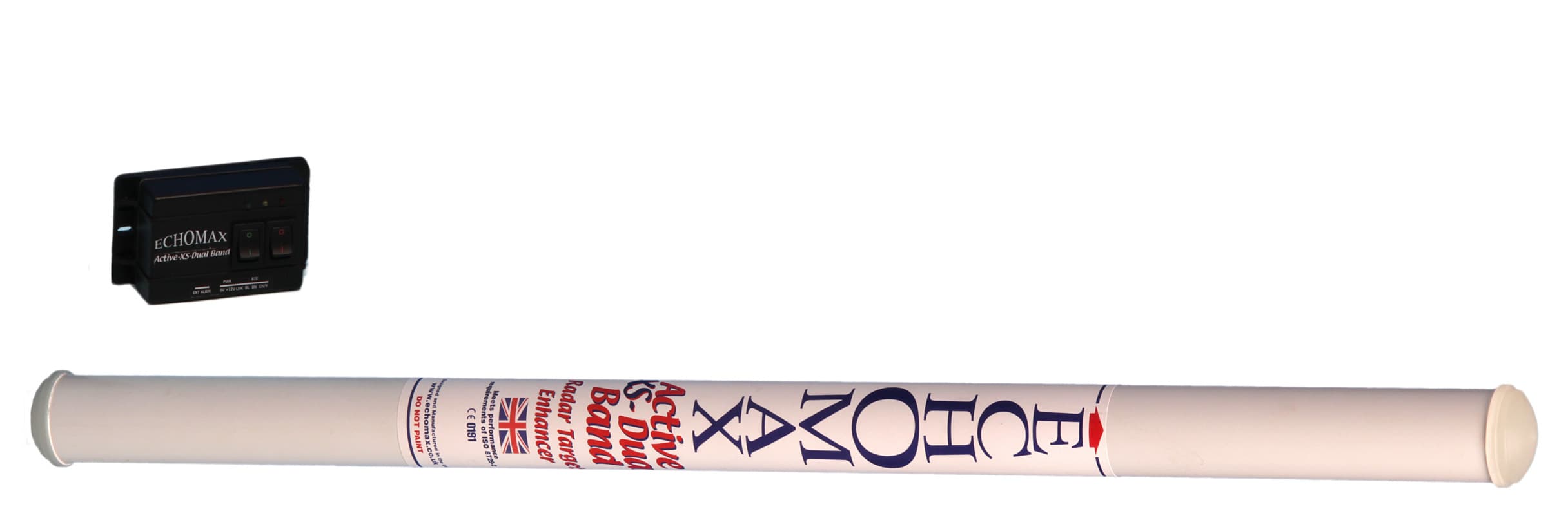
XZMACTIVE-XS
May 05, 2011Dual Band Radar Target Enhancer
Equipment Class
MRD - Marine Radar