XZMACTIVE-XSDual Band Radar Target Enhancer
Aquamate Products Limited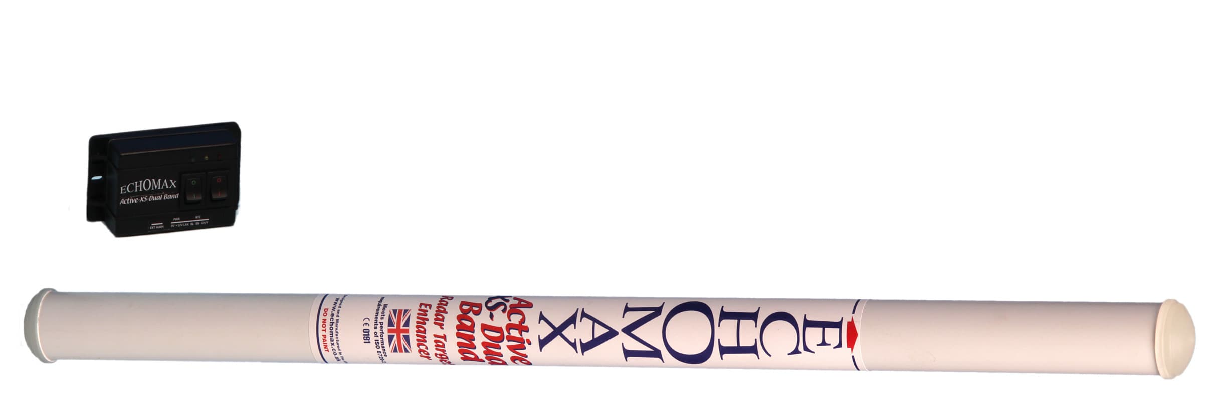
Click to zoom
Application Details
- Equipment Class
- MRD - Marine Radar
- Date of Grant
- May 05, 2011
- Application Purpose
- Original Equipment
- Date of Application
- Apr 04, 2011
- Equipment Note
- Dual Band Radar Target Enhancer
- Frequency Range
- 9300.00000000 - 9500.00000000
- Company
- Aquamate Products Limited
- Country
- United Kingdom
Documents & Files
Document Text
Text extracted from the exhibit documents filed with the FCC. Open a document above to read the original.
Users Manual
Ac t i v e-XS-D u a lBand Radar Target Enhancer ...asignificantadvanceinmarinesafety! Manufactured by Echomax Products in the UK PO Box 6032, Dunmow CM6 3AS, UK. Email: [email protected] www.echomax.co.uk Tel: 00 44 (0)1371 830216 Fax: 831733 OPERATIONMANUAL Ac t i v e-XS-D u a lBand Radar Target Enhancer ! GENERAL INTRODUCTION The Echomax Active-XS-Dual Band Radar Target Enhancer (RTE) is designed to respond to interrogating both X (9.3 - 9.5 GHz) and S band radar (2.9 - 3.1 GHz) by receiving a transmitted pulse, amplifying and re - t r a n s m i t t i n g the pulse back to the radar at the same frequency with minimum delay, thereby improving the radar detection range and visibility of small targets. It will not enhance significantly vessels with large radar cross section. The Active-XS-Dual Band Radar Target Enhancer is suitable for all vessels up to 150 gross tonnage. SOLAS V Regulation 19 2.1.7 states (Radar reflector):All ships irrespective of size shall have: if less than 150 gross tonnage and if practicable, a radar reflector, or other means to enable detection by ships navigating by radar at both 9 GHz (XBand) and 3 GHz. (S Band). The Active-XS-Dual Band Radar Target Enhancer will typically enhance the RCS (radar cross section) of vessels up to 25M in length. For small craft/rigid inflatables improvements will start to be seen at around 1-2 miles extending to 8-10 miles or more depending on prevailing conditions. The response of the RTE will vary according to range, RTE and radar height above sea level, radar power and condition. Poor weather, sea state and precipitation will greatly reduce the response. IMPORTANT The fitting of the Active-XS-Dual Band RTE does not exclude you from exercising safe navigational judgement for your vessel under the International Regulations for the Prevention of Collisions at Sea and to keep a proper look out at all times LICENSING REQUIREMENTS Many countries and administrations require a ships radio license or modification of your existing ships radio licence before the Active-XS can be used for maritime use. Contact your local administration for details. ECHOMAX ACTIVE-XS COMPONENTS, CONSTRUCTION, use and installation If you are not able to safely install the unit yourself you are advised to seek the services of a competent person or company to install the RTE. COMPONENTS Echomax Active-XS mast head radome fitted with 24 meters of 3 core cable Control box Operation manual RADOME FITTING The antenna has provisions in the base for a 1 inch -14 NF female thread mast fitting or deck mount bracket. Plastic mounts should not be used. To ensure a permanent fixing ‘LOCTITE’ or PTFE or plumbers tape should be used and the RTE must be screwed down tightly. Care must be taken to ensure that as the RTE is tightened on the base the cable is allowed to turn freely. For mast fitting the radome must be fitted vertically as high as possible. The receive/ transmit antennas positioned 70mm from the base of the radome must have a clear 360 degree azimuth. It should be fitted at least 6 inches/150mm from the mast on the offset bracket. It should not be fitted on a back stay or where its vision is obscured or is close to any metal object otherwise performance could be significantly impaired. The radome unit must never be painted as this will seriously impair performance. The radome must not be fitted in or close to the vessels radar vertical or horizontal transmitting beam as this may seriously d a m a g ethe PCB. The RTE should be fitted above the radar. It is possible to shorten the cable or extend by a further 25 meters without affecting thep e rf o rm a n c e using extension cable rated at 3A at 300V. ECHOMAX CONTROL BOX for surface fitting or flush mount with optional new flush mount kit Use and wiring instructions The control box must be fitted internally as it is not waterproof and can be wired from the base or back as required. A 12v fused or circuit breaker supply of 3-5A is required. The control box has a quadruple alarm facility. Once the red power switch is turned on the unit is in the quiescent mode and will consume up to 23mA. When interrogated by an X Band radar the green LED light will flash every 2.4 seconds. If the flash lengthens then this indicates that more than one radar is painting the antenna. If painted by a high speed radar which rotates every 1.5 seconds then the LED light will flash quicker. When painted by an S Band radar the yellow light will flash. It should be borne in mind that vessels with S Band radar are very large and in most cases over 3000GT and can neither stop nor change course quickly. Turning on the green switch will mobilize the i n t e rnal buzzer, which is set to actuate at appro x i m a t e l y half a second intervals. The control box also has facilities for a 8A external volt free alarm. THISISNOT APOWERSOURCE and must be initialised as shown in the wiring diagram. The control box has an externally replaceable 2 Amp fuse and is surge and cross polarity protected. All radars emit irregular vertical side lodes (spikes) and should the Active-XS be installed in the path of a spike it will think that it is being painted by another ships radar. Movement of the Active-XSradome to another position may remedy this, if not, the ships radar will need to be switched off. Identical radar may have a different side lobe pattern. Ac t i v e-XS-D u a lBand Radar Target Enhancer Ac t i v e-XS-D u a lBand Radar Target Enhancer RTECONNECTIONS The diagrams show the correct wiring installation PERFORMANCE CHECK As the RCS of your vessel may exceed the RCS of the RTE, the trial is best carried out at 0.5 nm as the target can be easily identified. The range should then be increased at intervals of 0.5 nm and the RTE switched on and off noting the change in response. As the range increases the bare target will not be seen and whilst moving the RTE is left on so that the test target can be seen at all times. This is important in busy waters to …
Text truncated - open the document above for the full version.
Cover Letter(s)
Federal Communications CommissionDA 10-2438 Before the Federal Communications Commission Washington, D.C. 20554 In the Matter of OCEAN SIGNAL LTD. Request for Waiver to Allow Certification and Use of a Dual Band Marine Radar Target Enhancer ) ) ) ) ) ) WT Docket No. 10-160 ORDER Adopted: December 29, 2010Released: December 30, 2010 By the Deputy Chief, Mobility Division, Wireless Telecommunications Bureau: 1.Introduction. This Ordergrants a request for waiver to permit the certification and use of maritime equipment that is not authorized by Part 80 of the Commission’s Rules. On June 21, 2010, Ocean Signal Ltd. (Ocean Signal), on behalf of Aquamate Products Ltd., filed a request for waiver of Section 80.375(d) of the Commission's Rules 1 to permit equipment certification and use of itsdual band, S- band (2.9-3.1 GHz) and X-band (9.3-9.5 GHz), Radar Target Enhancer (RTE). 2 For reasons set forth below, we grant Ocean Signal’s request for waiver. 2.Background.RTEs are used on small vessels to increase their detection and visibility to radarby receiving a radar signal from a passing vessel, amplifying the signal, and re-transmitting a stronger return signal. Chapter V of the International Convention for the Safety of Life at Sea (SOLAS) requires ships of less than 150 tons, if practicable, to have “a radar reflector, or other means, to enable detection by ships navigating by radar at both 9 and 3 GHz,” 3 but Section 80.375(d), which governs ship and shore radar and transponder frequencies above 2400 MHz, does not provide for the use of RTEs. Ocean Signal therefore seeks a waiver of Section 80.375(d). It states that its RTE will advance marine navigation safety by enhancing radar detection and visibility of small vessels. 4 3.Performance standards for radar reflectors have been issued by the International Maritime Organization (IMO) in Resolution MSC.164(78), 5 the International Organization for Standardization (ISO) in ISO 8729-2, 6 and the International Telecommunications Union (ITU) in ITU-R M.1176. 7 Except for the ISO standard, these standards are recognized in Chapter V of the SOLAS Convention carriage and 1 47 C.F.R. § 80.375(d). 2 Request for Waiver (filed June 21, 2010) (Waiver Request). On August 9, 2010, we sought comment on Ocean Signal’s waiver request. See Wireless Telecommunications Bureau Seeks Comment on Request by Ocean Signal Ltd. for Waiver to AllowCertification and Use of a Dual Band Marine Radar Target Enhancer, Public Notice, 25 FCC Rcd 10696 (WTB MD 2010). No comments were received. 3 SeeConsolidated Text to the International Convention for the Safety of Life at Sea (SOLAS), 2009, Chpt. V, Regulation 19.2.1.7. 4 See Waiver Request at 1. 5 IMO Resolution MSC.164(78), “Revised performance standards for Radar Reflectors,” adopted May 17, 2004. 6 ISO 8729-2, “Ship and marine technology –Marine radar reflectors –Part 2: Active type” (May 2009). 7 ITU-R M.1176, “Technical parameters of radar target enhancers” (1995). Federal Communications CommissionDA 10-2438 2 performance standard regulations. 8 4.Ocean Signal states thatits RTE meets these standards, with one exception. ITU-R M.1176 requires a minimum gain of 50 dB for both S-band and X-band RTEs. Ocean Signal argues, however, that this constitutes a discrepancy between ITU-R M.1176 and Resolution MSC.164(78), because requiring 50 dB gain for S-band RTEs results in an antenna that is both too large to be deployed on smaller vessels, and reflectsthe radar signal a significantly longer distance than required by Resolution MSC.164(78). 9 5.Discussion.Section 1.925(b)(3) of the Commission's Rules provides that we may grant a waiver if it is shown that (a) the underlying purpose of the rule(s) wouldnot be served or would be frustrated by application to the instant case, and grant of the requested waiver would be in the public interest; or (b) in light of unique or unusual circumstances, application of the rule(s) would be inequitable, unduly burdensome, or contrary to the public interest, or the applicant has no reasonable alternative. 10 We conclude that the waiver of the Commission’s Rules requested by Ocean Signal is warranted under the circumstances presented. Specifically, we conclude that the underlying purpose of the subject Commission rule would not be served by application to the instant case, and grant of the requested waiver would be in the public interest. RTEs provide small vessels increased detection and visibility to radar received from a passing vessel. Use of RTEs will serve the underlying purpose of Section 80.375, which is to authorize operation of ship and shore radar stations, and will serve the public interest by enhancing maritime safety. 6.Finally, we agree with Ocean Signal that its RTE should not be required to meet the all of the technical standards in ITU-R M.1176, at least with respect to non-SOLAS vessels. We believe that requiring a minimum gain of 50 dB for the S-band would render the device unsuitable for its intended use by necessitating an antenna that is too large to be practical for small, non-SOLAS, vessels. Instead, Ocean Signal’s RTE shall be required to meet the S-band technical standards in IMO Resolution MSC 164(87) in lieu of the minimum gain for the S-band required by the ITU standard for non-SOLAS vessels. 11 The device must meet all other applicable IMO, ISO, and ITU requirements. 7.All applications for equipment authorization pursuant to this waiver must be submitted to the FCC Laboratory. A copy of this Ordershall be submitted with the equipment authorization application. 8.Accordingly, IT IS ORDERED, pursuant to Sections 4(i) and 303(i) of the Communications Act of 1934, as amended, 47 U.S.C. §§ 154(i), 303(i), and Section 1.925 of the Commission's Rules, 47 C.F.R. § 1.925, that the Request for Waiver of Section 80.375(d) of the Commission’s Rules, 47 C.F.R. § 80.375(d), filed by Ocean Signal Ltd. on June 21, 2010, IS GRANTED to the extent specified herein. 8 See Consolidated …
Text truncated - open the document above for the full version.
External Photos
External Photos Figure 1: Echomax Active-XS Side View, showing product label and separate control box. The control box is purely for indication of status and is not part of this application. Figure 2: Active-XS Bottom View Figure 3: Active-XS Top View
ID Label/Location Info
FCC ID Label and Location The Product identity label will carry the FCC ID as shown. This label is permanently affixed to the body of the RTE as shown below. Figure 1: Product Label showing FCC identifier and location on product
Internal Photos
Internal Photos Figure 1: Active-XS RF assembly shown from S-band module side Figure 2: Active-XS RF assembly shown form X-band module side Figure 3: Active-XS RF assembly side view (S-band module at top of unit) Figure 4: X-band PCB Assembly showing X-band antennas Figure 5: X-band PCB Assembly Top Side Figure 6: X-band PCB Assembly Bottom Side: RF circuitry Note: this side covered in overall screening can, removed for this photo. Figure 7: S-band PCB Assembly: Component side Figure 8: S-band PCB assembly: Groundplane side Figure 9: S-band Antenna Assembly (One antenna each for receive and transmit mounted above the X-band antennas)
Test Report
Test Report to ITU-R M.1176 Echomax Active-XS Dual Band Radar Target Enhancer 4 th April 2011 OPERATIONAL TEST REPORT Product: Echomax Active-XS Dual Band RTE Page: 2 of 15 Serial No: N/A Date: 4 th April 2011 Report compiled by: David Sheekey Test Report: OPP004 This report cannot be reproduced, except in full, without the prior written permission of Ocean Signal Ltd. 1. Introduction 3 1.1. PRODUCT DESCRIPTION..................................................................................................................... 3 1.2. TEST LOCATIONS................................................................................................................................. 3 2. TEST SUMMARY................................................................................................................................... 4 2.1. TEST RESULT....................................................................................................................................... 4 2.2. TEST ACKNOWLEDGMENT................................................................................................................... 4 3. TEST EQUIPMENT USED................................................................................................................. 4 4. OPERATION TEST RESULTS......................................................................................................... 6 4.1. ANNEX 1, ITEM 1: ANTENNA PERFORMANCE................................................................................... 6 4.1.1. Test Method............................................................................................................................ 6 4.1.2. Equipment Used.................................................................................................................... 6 4.1.3. Results....................................................................................................................................... 7 Plots 1 and 2,........................................................................................................................................... 7 4.2. ANNEX 1, ITEM 2: BROADBAND OVER THE FREQUENCY RANGE.................................................... 7 4.2.1. Test Method............................................................................................................................ 7 4.2.2. Results....................................................................................................................................... 7 4.3. ANNEX 1, ITEM 2: AMPLIFICATION.................................................................................................. 8 4.3.1. Test Method............................................................................................................................ 8 4.3.2. Equipment Used.................................................................................................................... 8 4.3.3. Results....................................................................................................................................... 8 4.4. ANNEX 1, ITEM 2: OUTPUT FORM.................................................................................................... 8 4.4.1. Test Method............................................................................................................................ 8 4.4.2. Equipment Used.................................................................................................................... 8 4.4.3. Results....................................................................................................................................... 8 4.5. ANNEX 1, ITEM 2: E.I.R.P. AT LIMITING LEVEL.............................................................................. 8 4.5.1. Test Method............................................................................................................................ 8 4.5.2. Equipment Used.................................................................................................................... 9 4.5.3. Results....................................................................................................................................... 9 5. ANNEX A: PHOTOGRAPHS.......................................................................................................... 10 6. ANNEX B: RESULTS OF PERFORMANCE TESTS............................................................... 12 OPERATIONAL TEST REPORT Product: Echomax Active-XS Dual Band RTE Page: 3 of 15 Serial No: N/A Date: 4 th April 2011 Report compiled by: David Sheekey Test Report: OPP004 This report cannot be reproduced, except in full, without the prior written permission of Ocean Signal Ltd. 1. Introduction This test report covers the requirements for Echomax Active-XS Dual Band Active Radar Target Enhancer as specified in ITU-R M.1176(1995). The equipment was tested at the radar test range of QinetiQ Ltd., (Funtington) and data for this report has been calculated from results in the ISO8729-2 report number QINETIQ/TS/SDS/CR1002449. Supplementary testing was carried out in the facility of Ocean Signal Limited. Testing was carried out by Ocean Signal Ltd. on behalf of the Active-XS manufacturer:- Aquamate Products Ltd., Champers Farm, Bardfield End Green, Thaxted, Dunmow, Essex CM6 3PX 1.1. Product Description The equipment covered by this report comprised of the Active-XS Dual Band Radar Target Enhancer (RTE) and its associated terminal connection box. The Active-XS consists of dual receiving antennas, amplifiers and transmitting antennas. The Active- XS RTE is designed to enhance the determination of position of small targets by shipborne S-band radars used in the band 2900MHz - 3100MHz and by shipborne X- band radars used in the band 9300 – 9500MHz. The construction of the Active-XS is similar to that of the Active-X (FCC ID: XZMACTIVE-X). The S-band electronic module is mounted on the existing X-band assem…
Text truncated - open the document above for the full version.
Test Report
Commercial in Confidence QINETIQ/TS/SDS/CR1002449 Page 1 Commercial in Confidence This document is supplied by QinetiQ for Coverise Ltd under Contract No. COM-SDS-10-164-KG RCS and spurious emissions measurements of a dual band Coverise RTE (Active-XS) Steve Luke QINETIQ/TS/SDS/CR1002449 April 2010 "Any person finding this document should hand it to a police station or post it to the Group Security Manager, QinetiQ Limited, Cody Technology Park, Farnborough, Hampshire GU14 0LX, with particulars of how and where found. THE UNAUTHORISED RETENTION OR DESTRUCTION OF THE DOCUMENT MAY BE AN OFFENCE UNDER THE OFFICIAL SECRETS ACTS 1911 - 1989.” Copyright © Coverise Ltd. 2010 Commercial in Confidence QINETIQ/TS/SDS/CR1002449 Page 2 Commercial in Confidence Administration page Customer Information Customer reference number Purchase Order M012 Project title RCS and spurious emissions measurements of a dual band Coverise RTE (Active-XS) Customer Organisation Coverise Ltd. Customer contact Simon Nolan Contract number COM-SDS-10-164-KG Milestone number 1 Date due 16 th April 2010 Principal author Steve Luke Tel. 023 92 334858 QinetiQ Funtington Common Rd Funtington W Sussex PO18 9PD [email protected] Release Authority Name I. Boswell Post Programme Manager Date of issue Record of changes Issue Date Detail of Changes 1 st Issue 16 th April 2010 1 st Issue Commercial in Confidence QINETIQ/TS/SDS/CR1002449 Page 3 Commercial in Confidence List of contents 1 Introduction 5 2 Equipment under test 6 3 Measurement Techniques 7 3.1 Radar Cross Section (RCS) 7 3.2 Pulse Characteristics 8 3.3 Unwanted emissions 8 4 Summary of measurement results 13 5 Measurement Uncertainties 14 6 Conclusions 15 7 References 16 8 List of abbreviations 17 A Test Results 18 A.1 RCS results at S Band 18 A.2 RCS results at X Band 21 A.3 Pulse width results S Band 24 A.4 Pulse width results X Band 25 A.5 Spurious emissions and frequency of operation results S Band 26 A.6 Spurious emissions and frequency of operation results X Band 28 Commercial in Confidence QINETIQ/TS/SDS/CR1002449 Page 4 Commercial in Confidence List of Figures Figure 1 ACTIVE-XS dual band RTE mounted in the anechoic chamber 6 Figure 2 QinetiQ Funtington’s anechoic chamber with 300mm sphere being tested 7 Figure 3 Pulse Characteristics 8 Figure 4 Layout of facility for UE testing of RTE 9 Figure 5 Schematic of the Unwanted Emissions Measurement System 10 Figure 6 RCS vs azimuth angle of ACTIVE-XS dual band RTE at 3.05GHz 18 Figure 7 RCS vs azimuth angle of ACTIVE-XS dual band RTE at 3.05GHz 0 ̊ elevation – saturated power test 19 Figure 8 RCS vs time of ACTIVE-XS dual band RTE at S Band (2.9 to 3.1GHz) 20 Figure 9 RCS vs azimuth angle of ACTIVE-XS dual band RTE at 9.41GHz 21 Figure 10 RCS vs azimuth angle of ACTIVE-XS dual band RTE at 9.41GHz 0 ̊ elevation – saturated power test 22 Figure 11 RCS vs time of ACTIVE-XS dual band RTE at X Band (9.3 to 9.5GHz) 23 Figure 12 Pulse width measurement of ACTIVE-XS dual band RTE at S Band 24 Figure 13 Pulse width measurement of ACTIVE-XS dual band RTE at X Band 25 Figure 14 Frequency of operation plot of ACTIVE-XS dual band RTE at S Band 26 Figure 15 Spurious emissions measurement of ACTIVE-XS dual band RTE at S Band 27 Figure 16 Frequency of operation plot of ACTIVE-XS dual band RTE at X Band 28 Figure 17 Spurious emissions measurement of ACTIVE-XS dual band RTE at X Band 29 List of tables Table 1 Measurement equipment 12 Table 2 Table of results 13 Commercial in Confidence QINETIQ/TS/SDS/CR1002449 Page 5 Commercial in Confidence 1 Introduction A measurement programme was undertaken by QinetiQ Funtington to assess the radar cross section (RCS) and the spurious emissions from a dual band Coverise radar target enhancer (RTE); this RTE is to be marketed as the Echomax ACTIVE- XS dual band RTE. The task was performed under contract number COM-ICS-10-164-KG for Coverise Ltd. The equipment under test (EUT) has been tested against sections of active radar reflector RCS specification ISO 8729-2 [1] and R&TTE specification ETSI EN 302 752 [2]. The RCS and spurious emissions measurement results are summarised in a table in the main body of the report with the full results detailed in Annex A for comparison against the specifications. Commercial in Confidence QINETIQ/TS/SDS/CR1002449 Page 6 Commercial in Confidence 2 Equipment under test The EUT consisted of a ACTIVE-XS dual band RTE serial number 001 supplied by Coverise Ltd. Figure 1 shows a photograph of the ACTIVE-XS dual band in the anechoic chamber at Funtington. Figure 1 ACTIVE-XS dual band RTE mounted in the anechoic chamber Commercial in Confidence QINETIQ/TS/SDS/CR1002449 Page 7 Commercial in Confidence 3 Measurement Techniques 3.1 Radar Cross Section (RCS) The S and X band RCS measurements were carried out in the anechoic chamber at QinetiQ Funtington, figure 2. The chamber consists of a 15m long, 6m wide and 5m high screened room clad with radar absorbent material (RAM). The radar transmit and receive horns are mounted side by side and are positioned in the middle of the wall at one end of the chamber. At the other end, the target is positioned on a low RCS mount at the same height as the horns and this sits on an azimuth-over-elevation positioner which is screened by a small RAM wall. Figure 2 QinetiQ Funtington’s anechoic chamber with 300mm sphere being tested The facility uses a HP8530 vector network analyser with a HP8511A frequency converter unit as the calibrated radar. The system is computer controlled and the positioner data is synchronised with the measured RCS, which is plotted in real time. The RCS system is calibrated using a 300mm-diameter sphere with an RCS of -11.4dBm 2 (0.072m 2 ). The background clutter from the chamber is suppressed using an automated background subtraction method measured when the chamber is empty. For the main RCS testing the device was tested below its saturation level. For the saturated power tests at 0 ̊ elevation the RCS was tested …
Text truncated - open the document above for the full version.
Contact Information
Applicant
John H Simpson(Mr.)
Technical Contact
Ocean Signal LtdDavid Sheekey
[email protected]+44 1843 282930
Unit 4, Ocivan Way · Margate · United Kingdom
Non-Technical Contact
Ocean Signal LtdDavid Sheekey
[email protected]+44 1843 282930
Technical Specifications
| # | Rule Parts | Frequency Range | Power Output | Emission |
|---|---|---|---|---|
| 2 | 8 | 9.30 GHz - 9.50 GHz | 1 W | PON |
Other Applications from Aquamate Products Limited

XZMACTIVE-X
Jan 20, 2010Radar Target Enhancer
Equipment Class
SRT - Radar Transponder