Y2KCANBUSGW0271Radio Frequency Identification Device for Sample Carriers
Inpeco Spa a Socio Unico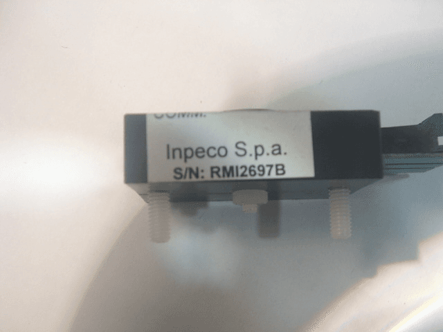
Click to zoom
Application Details
- Equipment Class
- DCD - Part 15 Low Power Transmitter Below 1705 kHz
- Date of Grant
- Mar 28, 2011
- Application Purpose
- Original Equipment
- Date of Application
- Mar 28, 2011
- Equipment Note
- Radio Frequency Identification Device for Sample Carriers
- Frequency Range
- 0.12500000 - 0.12500000
- Company
- Inpeco Spa a Socio Unico
- Country
- Italy
Documents & Files
Document Text
Text extracted from the exhibit documents filed with the FCC. Open a document above to read the original.
Users Manual
APTIO - Operations Manual2-1 799.007.203.0— February 2011 Section 2Security Security 1.General Security, Section 2-2 a.Security Notes, Section 2-2S b.Safety Labels, Section 2-3 2.Environmental and power specifications, Section 2-6 a.Environmental conditions, Section 2-6 b.Power requirements, Section 2-6 c.Compressed Air Requirements, Section 2-6 d.Manufacturer, Section 2-7 e.Waste Disposal, Section 2-7 f.Hazardous substances, Section 2-7 g.Installation Specifications, Section 2-8 h.Bar Code Reader Lasers, Section 2-8 i.Moving Parts, Section 2-8 j.Equipment Protection, Section 2-8 k.FCC warning statements, Section 2-8 SecuritySection 2 2 -2APTIO - Operations Manual 799.007.203.0— February 2011 General Security Personnel operating the automation must be proficient in its operation, maintenance, and procedures. To ensure safety, follow basic precautions. Security Notes Warnings, cautions, and notes are included throughout this manual to emphasize important instructions. WARNING: Defined as a physical, mechanical, or procedural condition that could result in moderate to serious personal injury . CAUTION: Defined as a condition that could result in minor injury or interfere with proper functioning of the Automation System. IMPORTANT: Defined as precautions which, if not followed, could cause a negative impact on system operations or assay results . NOTE: Defined as supplemental information that is relevant to the current subject matter. APTIO - Operations Manual2-3 799.007.203.0— February 2011 Section 2Security Safety Labels The following labels are affixed to the Automation System to alert the operator to safety considerations. IconDescription The operator should refer to the FlexLab 3.6 Operations Manual before performing procedures on the Automation System. Indicates the Automation System l was manufactured in the European Union in compliance with European regulations. Manufacturing location. Manufactured by Inpeco S.p.A. Segrate (MI) - Italy in Borgone di Susa Factory Plan. The Waste Electrical and Electronic Equipment (WEEE) indicates separate collections for electrical and electronic equipment. Dispose of electrical or electronic components in a separate container in accordance with local legislation. Rotate the knob to lock or unlock the cover Identifies the In Vitro Diagnostic device. Identifies for the U.S. and Canada: An Nemko-CCL mark that means the product is certified for both U.S. and Canadian markets to applicable U.S. and Canadian standards. SecuritySection 2 2 -4APTIO - Operations Manual 799.007.203.0— February 2011 Table Section 2.1: Labels IconDescription Identifies an area where operators can be exposed to moving parts. Be careful around these parts when performing diagnostics and maintenance operations with safety shield and covers removed. Identifies an activity that may present a safety-related hazard and advises the operator to consult the associated caution or warning instructions provided. Identifies an activity or area where operators may be exposed to potentially infectious material. Identifies an activity or area where the operator may be exposed to hot surfaces (> 70°C/158°F). Identifies an area containing cutting parts. Follow manufacturer instructions written in this guide when performing maintenance. Identifies the warn of electrical hazards. Identifies that hazardous voltage is present behind the protective cover. APTIO - Operations Manual2-5 799.007.203.0— February 2011 Section 2Security Avoid eye exposure to laser light. Do not stare into beam. Warns against direct viewing of the beam or reflections from the beam. •Input Output Module, Centrifuge Module and Storage and Retrieval Module cover lids should be opened completely to engage the locking mechanism. •When closing the Input Output Module, Centrifuge Module and Storage and Retrieval Module safety shields, pull out the lock and lower the safety shield. Use caution when opening the Input Output Module, Centrifuge Module and Storage and Retrieval Module safety shields to ensure they are fully open. Do not place objects on the top surface. Table Section 2.1: Labels IconDescription SecuritySection 2 2 -6APTIO - Operations Manual 799.007.203.0— February 2011 Environmental and power specifications Environmental conditions Table 2.2: Storage Conditions Power requirements Compressed Air Requirements DescriptionValue Operating altitude up to2000 meters above sea level Operating temperature range16° to 30° C Operating humidityMax 80% at 30°C Overvoltage Category I PollutionDegree 2 DescriptionValue Non Operating altitude up to12,000 meters above sea level Non Operating Humidity5% to 90% Non Operating Temperature-20°C to +60°C DescriptionValue Mains Line Frequency50/60 Hz Mains Line voltages fluctuationUp to ± 10 % • Mains Line Voltages depending on system configuration as follow: Single phase configuration with UPS230 V ~ 3680 VA Single phase configuration without UPS230 V ~ 9200 VA Three phases configuration without UPS400 V 3N ~ 27600 Mains Line voltages fluctuationsUp to ± 10 % DescriptionSpecification Compressed air must be cleanOil free and dry Compressed air pressure range7 to 9 bar APTIO - Operations Manual2-7 799.007.203.0— February 2011 Section 2Security Manufacturer This equipment is manufactured by Inpeco S.p.A. in Borgone di Susa factory plant. www.inpeco.com Inpeco S.p.A Via G. Di Vittorio, 11 - Segrate (MI) - ITALY Phone +39 (02) 36681300 - Fax +39 (02) 36681399. Viale Europa, 14. Borgone di Susa (TO) - ITALY Phone +39 (02) 36681400 - Fax +39 (02) 36681499. Waste Disposal Dispose of all waste produced during the workcell operation according to local, state, and country regulations. Treatment of waste electrical and electronic equipment. The product at the end of its useful life, should be disposed of following the rules for disposing differentiated and can not be treated as a simple urban waste. The product should be disposed of at collection centers or dedicated shall be returned to the dealer if y…
Text truncated - open the document above for the full version.
Users Manual
Doc.: HD0389-00-Manuale_TL_GWCxxxx_r.0.1_IT.doc-00 19/01/2005 Pag. 1 / 48 MAN.HIGWCxxxx Release 0.1 GWC _ _ _ _ MANUALE DI INSTALLAZIONE USO E MANUTENZIONE Doc.: HD0389-00-Manuale_TL_GWCxxxx_r.0.1_IT.doc-00 19/01/2005 Pag. 2 / 48 IMPORTANTE Questo documento è registrato dalla TECNOLOGIX e non può essere duplicato o riprodotto interamente o in parte senza l’espresso permesso scritto della TECNOLOGIX. TECNOLOGIX si riserva il diritto di apportare modifiche al manuale ed ai propri prodotti per migliorarne l’affidabilità e le prestazioni senza l’obbligo di aggiornare i prodotti e i manuali precedenti o di avvisare l’utilizzatore dei relativi cambiamenti. TECNOLOGIX non si assume la responsabilità di un uso del prodotto descritto in seguito non conformemente alle istruzioni indicate nel presente manuale. TECNOLOGIX S.R.L. VIA DEI BIANCOSPINI 6 20146 - MILANO - ITALY Tel. +39 0248954230 Fax +39 02471106 E-mail: [email protected] Web: www.tecnologix.it Ver. Verificato FA Data 0.1 0.2 0.3 Approvato Stampato in MILANO - ITALY 19/01/2005 Doc.: HD0389-00-Manuale_TL_GWCxxxx_r.0.1_IT.doc-00 19/01/2005 Pag. 3 / 48 GWC INDICE 1. INTRODUZIONE...............................................................................................................5 1.1. Componenti di un sistema............................................................................................5 1.2. GWC: descrizione........................................................................................................6 1.3. Composizione del GWC...............................................................................................7 1.4. Limiti d’uso, rischi e avvertimenti.................................................................................8 1.5. Garanzia......................................................................................................................9 1.6. In questo manuale.....................................................................................................10 2. SPECIFICHE..................................................................................................................11 2.1. Meccaniche (unità : mm)............................................................................................11 2.2. Elettriche....................................................................................................................13 2.2.1. Caratteristiche dell’alimentazione.......................................................................13 2.2.2. Specifiche elettriche I/O......................................................................................14 2.2.3. Interfaccia CAN Bus - CANOpen........................................................................16 2.2.4. Interfaccia CAN Bus - DeviceNet........................................................................17 2.2.5. Interfaccia PROFIBUS DP..................................................................................18 2.2.6. Interfaccia RS232 e RS485.................................................................................19 3. INSTALLAZIONE DEL CONTROLLORE........................................................................20 3.1. Rimozione dell’imballo, ispezione e immagazzinamento...........................................20 3.2. Impostazioni utente: impostazioni Dip-switch.............................................................21 3.3. Installazione e utilizzo dell’unità in sicurezza.............................................................22 3.4. Montaggio dell’apparato.............................................................................................23 3.5. Connessione del GWC..............................................................................................25 3.5.1. CN1: Connessione alla terra di protezione (EG).................................................27 3.5.2. CN1: Connessione all’alimentazione DC (PS)....................................................28 3.5.3. CN2: Connessione al CanOpen #1.....................................................................30 3.5.4. CN3: Connessione al DeviceNet (o CanOpen #2)..............................................31 3.5.5. CN4 CN5: Connessione dell’interfaccia RS232 e RS485 #1 #2.........................32 3.5.6. CN6: Connessione degli ingressi........................................................................34 3.5.7. CN7: Connessione delle uscite...........................................................................35 3.5.8. CN8 : Connessione dell’interfaccia PROFIBUS DP............................................36 3.5.9. CN12 CN13: Connessione dei TRASPONDERs.................................................38 4. AVVIAMENTO DEL CONTROLLORE............................................................................39 4.1. Verificare l’installazione.............................................................................................39 4.2. Manutenzione............................................................................................................39 4.3. Stati di funzionamento e loro segnalazioni.................................................................39 4.4. Tabella di ricerca guasti.............................................................................................40 5. VERSIONI E SPECIFICHE GWC...................................................................................42 5.1. Codifica del Controllore e Informazioni di ordine........................................................42 5.2. Versioni di GWCxxxx disponibili.................................................................................42 5.3. Specifich\e tecniche...................................................................................................43 A. APPENDICI....................................................................................................................44 A.1 Connessioni Utente............................................................…
Text truncated - open the document above for the full version.
Cover Letter(s)
Dp..o Date 20th December 2010 Nemko Canada Inc 303 River Road Ottawa, Ontario, Canada KMH2 Attn: Director of Ceftification Authoritv to Act as Aqent On our behalf, I appoint Nemko Spa - via del Carroccio n. 4, Biassono (MB) ltaly to act as our agent in the preparation of this application for equipment certification. I certify that submitted documents properly describe the device or system for which equipment certification is sought. I also certify that each unit manufactured, imported or marketed, as defined in the Federal Communications Commission's regulations will have affixed to it a label identical to that submitted for approval with this application. For instances where our authorized agent signs the application for certification on our behalf, I acknowledge that all responsibility for complying with the terms and conditions for certification, as specified by Nemko Canada Inc, still resides with Inpeco Spa - Via G. Di Vittorio 11 - 20090 Segrate (Ml) ltaly. Dated 20th this Day of December 2010 Agency agreement expiration date: Usually Give I - 12 Months By:r:fu Title: Robefto'Tamborra Signature Printed Quality Assurance and Regulatory Manager On behalf of :lnpeco Spa Via G. Di Vittorio, 11 20090 Segrate (Ml) ltaly Telephone: +39 02 36681263 **pec* *S* I $olc tnltn+f 1t)*rr';e:r'í *ìJf:ùcl ?t i.lÌf dilîi:t.iox i1(l rci'iìr*1i*11 o:" Jnilocc ùrti:l $Al w,.';''i,,.iiri:ofo.i#r': SegrfitsilVli) |Vi*ff.il; Vli{*ri* if..$+gr*rc:\il.\-:IALY IPir+rr+39í*?i 3S$8;i3t+ ìta.r+39itj2) 3{r$Sl:j9* Eorg*** c{i $csa {To} | Vi*:* [i:r*;i3, 1,4. B+rg+r* aì 9r;** i:*) I;ALY i liúr,í] *3S i*21 3$681"4ùCI I i*.1 .3* arj:i 3SSfi j.4î] *.È"&. &4í*a** r:. 1ù39llll- - $ser. Ysi*. ffliX*rue 1ú$S14 V3:. $5it Fesl. l-4 - VA? **d* **E:OÒ$Ol-5S
Cover Letter(s)
@p..o Date 20th December 2010 Equipment Autorisation Division Federal Communications Commission 7435 Oakland Mills Road Columbia, MD 21046 FCC lD: Y2K CANBUSGWO271 Product Name: CANBUS ANTENNA Req uest for Confidential itv Pursuant to Sections 0.457 and 0.459 of the following documents be held confidential: commissions rules, we hereby request that the (List here the documents for which you are seeking confidentiality - for example ... ) o Schematics o Block diagram o Parts list These materials contain trade secrets and proprietary information and are not customarily released to the public. The public disclosure of this information might be harmful to the company and provide unjustified benefits to our competitors. Dated 20th this Day of December 20 10 By: i Roberto Tamborra Signature Title: Quality Assurance Manager Printed On behalf of : lnpeco S.p.A. Via G. Di Vittorio, 11 20090 Segrate (Ml) ltaly Telephone: +39 02 36681263 È*pee* *g*e | $*le i]*.!.*e | | Cr:rrirarry $'Jb:ocl li tlro dilr.ti*| arl.j c*tjtt){:azìon ol lnúec* ùrr:1.;r $Al w'-r--w.iri}scc.c*l: Segr;at* {#l$} | Viil *. n: ViitoriÒ, : $og.arc ii'J1i .- :fAty J fiioli: -Jg i*2.i 3$6g:j 3CS : í;lx +3t í02; 3068:t39$ Sorg*n* di $u$a {îs} I vr*ì* Èitrsl;3, 1-4. 3+rgcr* cì $r";ll íî0) ;TALY i sicx€ +3e i$2;366*140$ | iax *39 irj!) 3$iig:_4tt R.€'4,. fd?ifano tl' l-C395*X- !s*r- Trib" lVîàila** l-S511-4 V*;. $*i* iasc. 14 - VAY **de ')$g:Có6ùJ_3S
Cover Letter(s)
To Whom lt May Concern The undersigned Roberto Tamborra, as Representative of Inpeco, under his responsibility declares that the product APTIUS must be instatted and serviced onty by professionat and trained personnef . lssued on Juanuary 17,?:011 in Segrate, ltaly Quatity Assurance Manager Roberto Tamborra lnpeco spa I Sole partner I Company subject to the direction and coordination of Inpeco Group SA I www.inpeco.com seEfate (Ml) | Via G. DiVittorio, 11. segrate (Ml) - ITALY I Phone +39 (02) 36681300 | Fax +39 (02) 36681399 Borgone di Susa (To) | Viale Europa, 14. Borgone di Susa (TO) - ITALY I Phone +39 (02) 36681400 | Fax +39 (02) 36681499 R.E.A. Milano n. 1039501 - lscr. Trib. Milano 195514 Vol. 5510 Fasc. 14 - VAT code 05820660156
ID Label/Location Info
Model: CANBUS ANTENNA FCC ID:Y2KCANBUSGW0271 This device complies with Part 15 of the FCC rules subject to the following two conditions: 1) This device may not cause harmful interference 2) This device must accept all interference received, including interference that may cause undesired operation.
Operational Description
DATA SHEET Product specification 1998 Jul 10 INTEGRATED CIRCUITS PCF7931AS Programmable Identification Transponder (PIT) 1998 Jul 102 Philips SemiconductorsProduct specification Programmable Identification Transponder (PIT)PCF7931AS CONTENTS 1FEATURES 2GENERAL DESCRIPTION 3ORDERING INFORMATION 4QUICK REFERENCE DATA 5BLOCK DIAGRAM 6MODULE (STICK) 6.1General Functional Description 6.2Limiting values 6.3Electrical Characteristics 6.4READ_MODE 6.4.1Measuring setup 6.5PROGRAM_MODE 6.6Mechanical Characteristic 7FUNCTIONAL DESCRIPTION OF THE IC 7.1Memory organization and access 7.1.1Password/Pac 7.1.2Protection 7.1.3Sync-pattern 7.1.4Selection 7.2Contactless Interface 7.2.1Supply voltage 7.2.2Reset 7.2.3System clock 7.2.4Modulation/Coding 7.2.5Logic 7.3Data Transmission from transponder to basestation (READ_MODE). 7.4Switching between read and program (PROGRAM_MODE_CHECK) 7.5Data transmission from basestation to transponder (PROGRAMM_MODE) 7.6Synchronization from PIT 7.6.1NOTES TO FIGURES 13, 14 8STRUCTURE OF CIRCUIT 8.1Functional diagram 8.1.1Rectifier 8.1.2Voltage clamp circuit 8.1.3CDP data clamp 8.1.4Clock generator 8.1.5Demodulator 8.1.6Control logic + EEPROM 8.1.7Damping Circuit 8.1.8Charge pump 8.1.9Power-on reset 9ANOMALY NOTES (VERSION V0) 10DEFINITIONS 11LIFE SUPPORT APPLICATIONS 1998 Jul 103 Philips SemiconductorsProduct specification Programmable Identification Transponder (PIT)PCF7931AS 1FEATURES •Identification Transponder for use in contactless applications •Programmable read only operation •Non volatile memory of 1024 bits (768 bits user data, 256 bits control data) •Periodically data read out during READ_MODE •Data transmission and supply energy via RF link •Write protection •7 byte password •Operating/resonance frequency 125 kHz nominal •20 years non-volatile data retention •100 erase/write cycles per byte •Extended temperature range−40°Cto+85°C •Assembled as plastic stick 2GENERAL DESCRIPTION The PCF7931AS is a “Programmable Identification Transponder” (PIT) which transmits data bidirectionally, in half duplex mode, between basestation and transponder. Data are stored in the transponder in a non-volatile memory (EEPROM). The transponder requires no internal power supply; it derives its power from the magnetic component of the RF signal generated by the basestation. Data are transmitted by modulating the RF-signal. The device has been specially designed for identification purposes where reprogramming of the identification code or storage of additional data is required, e.g. car immobilizer. The EEPROM has a memory capacity of 128 bytes and is organized in eight blocks, each having 16 bytes. Capacity is split into six blocks (96 bytes) for programming/reading of user data and into two blocks (32 bytes) for control of the memory access. The PCF7931AS contactless interface generates the power supply and system clock from the resonant circuit by inductive coupling to the basestation. The interface also demodulates data that are transmitted from the basestation to the PIT, and modulates the electromagnetic field for data transmission from PIT to station. When the PIT enters an RF field the contactless interface generates a reset and then goes into READ_MODE. In this mode the PIT cyclically transmits all data blocks to the basestation. Modulation and coding of data in READ_MODE (PIT to basestation) is carried out by Amplitude Key Shifting with Diphase Coding. As a result of the inductive coupling between the circuit and basestation antenna, the current in the antenna is also modulated, resulting in low level amplitude modulation. 3ORDERING INFORMATION EXTENDED TYPE NUMBERIC VERSIONPACKAGEDRAWING TEMPERATURE RANGE (°C) PCF7931AS/3851V0SOT385-1SOT385BA3−40 to +85 1998 Jul 104 Philips SemiconductorsProduct specification Programmable Identification Transponder (PIT)PCF7931AS 4QUICK REFERENCE DATA 5BLOCK DIAGRAM PARAMETERVALUEUNIT Carrier frequency (nominal)125kHz Magnetic flux density •read •program 25 170 μWb/m 2 (min.) peak to peak μWb/m 2 (typical) peak to peak Data transmission modehalf-duplex Transfer rate •read •program 1.95 0.98 kbit/s kbit/s Coding •read •program CDP (conditioned diphase) PPM (pulse position modulation) ModulationASK (amplitude shift keying) Memory size128byte Memory organization8 blockseach 16 byte Weight0.427g Package dimensions3 x 6 x 12mm Electro magnetic susceptibilityaccording to DIN 40839, part 4 Special features•7 byte password •blockwise write protection •user defined irreversible write protection Fig.1 Blockdiagram transponder. ANALOG INTERFACE ACCESS CONTROL EEPROM 128 BYTE PCF7930 V0 PCF7931AS 12 mm 6 mm 1998 Jul 105 Philips SemiconductorsProduct specification Programmable Identification Transponder (PIT)PCF7931AS 6MODULE (STICK) 6.1General Functional Description The “Programmable Identification Transponder” (PIT) allows the contactless reading and programming of data into a memory. Data are transmitted bidirectionally in half duplex mode between basestation and the PIT. Data are stored in a non volatile memory (EEPROM). The PIT does not require any additional external power supply. It derives its power supply from the magnetic component of the RF-radiation which is generated by the basestation. Data are transmitted by modulating the RF-radiation. The PIT has especially been designed for identification purposes where reprogramming of the identification code or storage of additional information is required. A block diagram of the system is given in Fig.2. The PIT consists of a coil, a capacitor and the IC. On the IC the following functions are integrated: •EEPROM: 128 byte non volatile memory (96 byte user, 32 byte control) •CIF (contactless interface): power supply, clock recovery, data handling The basestation generates an RF-field with a frequency of nominal 125 kHz. The PIT is synchronized on this “system clock”. The two operating modes of the PIT are READ_MODE and PROGRAM_MODE. The PIT is switched between these two modes under control of the base…
Text truncated - open the document above for the full version.
Operational Description
DATA SHEET Product Specification (Rev. 1998 Apr 20) printed 1998 Apr 20 INTEGRATED CIRCUITS PCF7991AT Advanced Basestation IC printed 1998 Apr 202 Philips SemiconductorsProduct Specification (Rev. 1998 Apr 20) Advanced Basestation ICPCF7991AT CONTENTS 1FEATURES 2GENERAL DESCRIPTION 3ORDERING INFORMATION 4BLOCK DIAGRAM 5QUICK REFERENCE DATA 6PINNING INFORMATION 6.1Pinning Diagram 6.2Pin Description 7MINIMUM APPLICATION CIRCUITRY 8FUNCTIONAL DESCRIPTION 8.1Power Supply 8.2Antenna driver 8.3Modulator 8.4Oscillator 8.5Receiver 8.5.1Synchron Demodulator 8.5.2Bandpass Filter, Amplifier and Digitizer 8.5.3Phase Measurement 8.5.4Determining the Sampling Time 8.5.5Data Amplitude Comparison 8.5.6System Diagnostics 8.6Power-on reset 8.7Power-down modes 8.8Serial Interface 8.8.1Serial Interface Mode 9COMMAND SET 9.1READ_TAG 9.2WRITE_TAG_N 9.3WRITE_TAG 9.4READ_PHASE 9.5SET_SAMPLING_TIME 9.6GET_SAMPLING_TIME 9.7SET_CONFIG_PAGE 9.8GET_CONFIG_PAGE 10LIMITING VALUES 11DC CHARACTERISTICS 12AC CHARACTERISTICS 13PACKAGE 14DEFINITIONS 15LIFE SUPPORT APPLICATIONS printed 1998 Apr 203 Philips SemiconductorsProduct Specification (Rev. 1998 Apr 20) Advanced Basestation ICPCF7991AT 1FEATURES •Fully integrated single chip basestation •Compatible with PCF79xx transponder family •Robust antenna coil power driver stage with modulator •High performance adaptive sampling time AM/PM demodulator (patent pending) •Read and write function •Programmable modulator/demodulator characteristics •On-chip clock oscillator and divider in the case of external clock reference •Antenna rupture and short circuit detection •Low power consumption •Very low power stand-by mode •Low external component count •Small package (SO14). 2GENERAL DESCRIPTION The PCF7991AT is a fully integrated Advanced Basestation IC, ABIC, designed for car immobilizer systems providing read and write access to an identification transponder. The device is intended for use with the Philips transponder family (PCF79xx) as well as other transponder types operating at 125 kHz and employing ASK, Amplitude Shift Keying for write and AM/PM for the read operation. The receiver characteristics (amplifier gain, filter cutoff frequencies) can be optimized to system and transponder requirements. The PCF7991AT IC is designed for easy integration into immobilizer read/write and read-only systems featuring a high degree of integration and very low external component count. The device integrates a powerful antenna driver/modulator, a low-noise adaptive sampling time demodulator, programmable filters/amplifier and digitizer, required to design high-performance basestations. A three wire microcontroller interface is provided for programming the PCF7991AT as well as for the bidirectional communication with the transponder. The three-wire interface can be configured for two wire operation by connecting the data input and the data output. The device employs a unique Adaptive Sampling Time (AST) demodulation technique, that extends the system operation range and eliminates the effect of a zero amplitude modulation response from the transponder, as a result of resonance frequency tolerances. 3ORDERING INFORMATION EXTENDED TYPE NUMBER PACKAGE TEMPERATURE RANGE (°C) NAMEDESCRIPTIONVERSION PCF7991AT/1081SO14plastic small outline package; 14 leadsSOT108-1−40 to +85 printed 1998 Apr 204 Philips SemiconductorsProduct Specification (Rev. 1998 Apr 20) Advanced Basestation ICPCF7991AT 4BLOCK DIAGRAM Fig.1 Blockdiagram advanced basestation PCF7991AT. Antenna Drivers Modulator Control Unit Oscillator Serial Interface Control Register Synchron Demodulator Phase Measurement Bandpass Filter Amplifier Dynamic Control Digitizer TX1 TX2 RX QGNDCEXT V SS XTAL1 XTAL2 D IN D OUT SCLK V DD MODE 5QUICK REFERENCE DATA PARAMETER VALUE MIN.MAX.UNIT Supply voltage4.55.5V Power-down current20μA Clock/Oscillator frequency (antenna carrier frequency 125 kHz) 416MHz Antenna driver current400mA p Receiver sensitivity2mV pp Serial interfaceCMOS compatible PackageSO14 Operation temperature range−40°C to +85°C printed 1998 Apr 205 Philips SemiconductorsProduct Specification (Rev. 1998 Apr 20) Advanced Basestation ICPCF7991AT 6PINNING INFORMATION 6.1Pinning Diagram Fig.2 Pinning diagram for PCF7991AT. 1 2 3 4 5 6 7 14 13 12 11 10 9 8 PCF7991AT Pin 1 ID V SS TX2 V DD MODE TX1 XTAL1 XTAL2 SCLK N.C. D OUT D IN CEXT QGND RX 6.2Pin Description Table 1Pin description for PCF7991AT SYMBOL PINDESCRIPTION V SS 1Common ground, GND. TX22Antenna driver output. V DD 3Supply voltage input, stabilized. TX14Antenna driver output. MODE5Microcontroller interface mode select. XTAL16Oscillator interface, external clock reference input. XTAL27Oscillator interface. SCLK8Microcontroller interface: serial clock input. D IN 9Microcontroller interface: serial data in. D OUT 10 Microcontroller interface: serial data out. N.C.11 Not connected. CEXT12 High pass filter decoupling. QGND13 Analog ground bias. RX14 Receiver input. printed 1998 Apr 206 Philips SemiconductorsProduct Specification (Rev. 1998 Apr 20) Advanced Basestation ICPCF7991AT 7MINIMUM APPLICATION CIRCUITRY The following figure shows a minimal application circuitry for the PCF7991AT. The antenna coil L a together with the capacitor C a form a series resonant LC circuit (f = 125 kHz). The antenna tap voltage is attenuated by R V and the input impedance of the RX-pin. The capacitors at XTAL1 and XTAL2 are selected according to the crystal or ceramic resonator specification. In the case of an external clock reference they may be omitted. The capacitors at QGND and CEXT are for device internal biasing and decoupling purposes. Fig.3 Minimum application circuitry V DD 10μF + 100nF L a C a R v XTAL1 XTAL2 V DD D IN D OUT SCLK TX1 TX2 RX QGND CEXTV SS 100nF100nF TO MICRO- PROCESSOR MODE printed 1998 Apr 207 Philips SemiconductorsProduct Specification (Rev. 1998 Apr 20) Advanced Basestation ICPCF7991AT 8FUNCTIONAL DESCRIPTION 8.1Power Supply The PCF7991AT operates from an external 5 V power s…
Text truncated - open the document above for the full version.
Test Report
www.nemko.com Nemko Spa Via del Carroccio, 4 – I 20046 Biassono (MB) Report number: 154942-1TRFWL Apparatus: Radio Frequency Identification Device for Sample carriers Applicant: INPECO S.p.A. Via G.Di Vittorio 11, 20090 Segrate (MI) FCC ID: Y2KCANBUSGWO271 Test specification: Title 47 - Telecommunication Chapter I - Federal Communications Commission Subchapter A - General Part 15 - Radio Frequency Devices Subpart C - Intentional Radiators Tested by: 2011-03-21 Signature Date Daniele Guarnone, Wireless/EMC Specialist Reviewed by: Signature Gabriele Curioni, Wireless/EMC Specialist Nemko Spa authorizes the applicant to reproduce this report provided it is reproduced in its entirety and for use by the company’s employees only. Any use which a third party makes of this report, or any reliance on or decisions to be made based on it, are the responsibility of such third parties. Nemko Spa accepts no responsibility for damages, if any, suffered by any third party as a result of decisions made or actions based on this report. This report shall not be reproduced except in full without the written approval of the testing laboratory. Report Number: 154942-1TRFWL Nemko Spa Via del Carroccio, 4 – I 20046 Biassono (MB) Specification: FCC 15 subpart C Page 2 of 35 Table of contents Section 1: Report summary................................................................................................................... 3 Section 2: Equipment under test .......................................................................................................... 4 2.1 Identification of equipment under test (EUT) ............................................................................ 4 2.2 Accessories and support equipment.........................................…
Text truncated - open the document above for the full version.
Contact Information
Applicant
Cristian Leotta(Certification Engineer)
Technical Contact
Non-Technical Contact
Inpeco S.p.ARoberto Tamborra
[email protected]39-02-36681263
Test Firm
Nemko SpARalph Spanevello
Technical Specifications
| # | Rule Parts | Frequency Range | Power Output |
|---|---|---|---|
| 1 | 15C | 0.125 MHz - 0.125 MHz | - |
Other Applications from Inpeco Spa a Socio Unico

Y2K-CAB1C001
Jan 28, 2020RFID-Radio Frequency Identification Device for Sample Carriers
Equipment Class
DCD - Part 15 Low Power Transmitter Below 1705 kHz
Y2K-CAB2C001
Jan 28, 2020RFID-Radio Frequency Identification Device for Sample Carriers
Equipment Class
DCD - Part 15 Low Power Transmitter Below 1705 kHz
Y2K-CANLANSI001
Sep 27, 2014Radio Frequency Identification Device for Sample carriers
Equipment Class
DCD - Part 15 Low Power Transmitter Below 1705 kHz