Y4GCU600-2Two Way Radio
SHENZHEN COVALUE COMMUNICATIONS CO., LTD.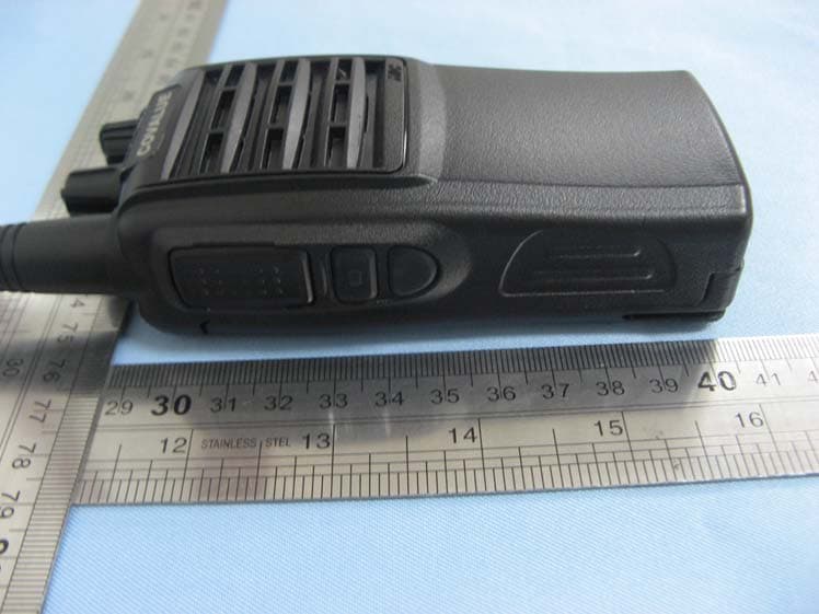
Click to zoom
Application Details
- Equipment Class
- TNF - Licensed Non-Broadcast Transmitter Held to Face
- Date of Grant
- Apr 18, 2011
- Application Purpose
- Original Equipment
- Date of Application
- Apr 18, 2011
- Equipment Note
- Two Way Radio
- Frequency Range
- 406.20000000 - 469.96500000
- Country
- China
Documents & Files
Document Text
Text extracted from the exhibit documents filed with the FCC. Open a document above to read the original.
Users Manual
Instruction Manual CU600- Two Way Radio Notice to the User: · Please read this instruction manual before operating this radio. · It’s prohibited to use the radio or charge it at any area with a potentially explosive atmosphere (where th e air contains gas, dust and smog, etc.), such as while taking on fuel, or while parking at a gasoline service station; or any area where radio communication is prohibited (such as a hospital or a airport.) · It’s prohibited to operate the radio without permissi on at the areas where the government laws prohibit radio communication. · Please don't expose the radio to direct sunlight for a long time; don't place the radio near any heatin g devices, either. · Please don't put the radio in extremely dusty, m oist or dabbling places; don’t place it on any unstable surfaces, either. · If you want to develop or remodify the radio · Refer service to the well-trained professional technicians only and do not disassemble or assemb le the radio. SHENZHEN COVALUE COMMUNICATIONS Co., Ltd. 1 W AR N IN G Your radio generates RF electromagnetic en- ergy during transmit mode. This radio is designed for and classified as “Occupational Use Only”, meaning it must be used only during the course of employment by individuals aware of the hazards, and the ways to minimize such hazards. This radio is NOT intended for use by the “General Population” in an uncon- trolled environment. This radio has been tested and complies with the FCC RF ex- posure limits for “Occupational Use Only”. In addition, your radio complies with the following Standards and Guidelines with regard to RF energy and electromagnetic energy levels and eval- uation of such levels for exposure to humans: • FCC OET Bulletin 65 Edition 97-01 Supplement C, Evaluat- ing Compliance with FCC Guidelines for Human Exposure to Radio Frequency Electromagnetic Fields. • A me rican National Standards Institute (C95.1-1992), IEEE Standard for Safety Levels with Respect to Human Exposure to Radio Frequency Electromagnetic Fields, 3 kHz to 300 GHz. • Ame rican National Standards Institute (C95.3-1992), IEEE Recommended Practice for the Measurement of Potentially Hazardous Electromagnetic Fields– RF and Microwave. • The following accessories are authorized for use with this product. Use of accessories other than those specified may result in RF exposure levels exceeding the FCC requirements for wireless RF exposure.; Belt Clip, Rechargeable Li-Ion Battery Pack, Charger. C AU TIO N To ensure that your expose to RF electromag- netic energy is within the FCC allowable lim- its for occupational use, always adhere to the following guidelines: • DO NOT operate the radio without a proper antenna at- tached, as this may damaged the radio and may also exceed FCC RF exposure limits. A proper antenna is the antenna supplied with this radio or antenna specifically authorized for use with this radio. • DO NOT transmit for more than 50% of total radio use time (“50% duty cycle”). “50% duty cycle” is also applicable to PSTN (Public Switched Telephone Network) mode and VOX Mode .Tr ansmitting more than 50% of the time can cause FCC RF exposure compliance requirements to be exceeded. The radio is transmitting when the TX indicator lights red. You can cause the radio to transmit by pressing the “PTT” switch. • ALWAYS keep the antenna at least 2.5 cm (1 in.) away from the body when transmitting and only use the Icom belt-clips listed on p. 24 when attaching the radio to your belt, etc., to ensure FCC RF exposure compliance requirements are not exceeded. To provide the recipients of your transmission the best sound quality, hold the antenna at least 5 cm (2 in.) from your mouth, and slightly off to one side. The information listed above provides the user with the informa- tion needed to make him or her aware of RF exposure, and what to do to assure that this radio operates with the FCC RF expo- sure limits of this radio. 25 SAFETY TRAINING INFORMATION CONTENTS ■ Unpacking and Checking the Equipment Supplied Accessories ■ Preparat ion Char ging the Battery Installing/Removing the Battery Pack Installing the Antenna Installing the Optional Speaker/Microphone Installing/Removing the Belt Clip ■ Radio Overview ■ Basic Operations ■ Programmable Button Function ■ VOX (Voice Operated Transmission) ■ Wired Cloning Mode ■ Radio Setting TOT (Time-out Timer) Battery Save Low Power Warning Channel Annunciation CTCSS/DCS ■ User Template RX Squelch Mode DTMF 5-Tone Signaling ■ Troubleshooting ■ Settings 2 ■ Unpacking and Checking the Equipment Unpack the radio carefully. We recommend that you identify the items listed in the following table before discarding the packing material. If any items are missing or have been damaged during shipment, please contact the carrier or the dealer immediately. Supplied Accessories Item Quantity Antenna 1 Hand Strap 1 Belt Clip 1 Lithium Battery 1 Charger 1 Power Adapter 1 Dust Cover 1 Instruction Manual 1 An tenna Po wer Adapter Belt Clip Charger Hand Strap Li-Polymer Battery 1、Open Pac k age Inspection Firstly, please take the radio out of the package box caref ully. We recommend checking the radio and the supplied accessories in the following table carefully. If any article is found lost or damaged, please contact the distributor without delay. Package List Accessories Quantity 1 Mainframe 1 2 Antenna 1 3 Battery 1 4 Charger 1 5 Power Adapter 1 6 Cord 1 7 Belt Clip 1 8 User Manual 1 9 Warranty Card 1 3 2、Preparation 2.1 Charging the Battery Plug the power adapter into the proper AC wall outlet; and insert the cable of the power adapter into the adapter socket on the charger; Red LED flashes after it enters normal work.(Red LED lights per 3 seconds) Insert the battery or the radio to be charged into the charger slot. Turn off the radio before insert it into the charger. Make sure the battery is in good contact with the charger terminals. When the red indicator lights, the charger be gins to charge the battery. After charging f…
Text truncated - open the document above for the full version.
Cover Letter(s)
SHENZHENCOVALUECOMMUNICATIONS CO.,LTD Tel.:86-755-86345789 Fax:86-755-86345789 Rm 408,Water Group Building, No.5 KYLIN Road, Nanshan Dsitrict, Shenzhen, China Confirmation Letter For Protecting against using 25 KHz channel separation FCC ID: Y4GCU600-2 Date: Apr. 19,2011 Federal Communications Commission Authorization and Evaluation Division 7435 Oakland Mills Road Columbia, MD 21046 To whom it may concern: We, the undersigned, hereby confirm that the channel separation of 25 KHz will be disabled by configuring the firmware during the final production. We had well understood the requirements of FCC regarding to the issue and we will guarantee that the final products supporting only 12.5 KHz channel separation will be produced and supplied to the U.S. Market. Sincerely, SHU CHENG TAO / ENGINEER
Cover Letter(s)
Jan. 04, 2011 Federal Communications Commission Authorization & Evaluation Division 7435 Oakland Mills Road Colombia, Maryland 21046 Subject: FCC ID: Y4GCU600-2 Attestation statement that the end user can’t tune the transmitter. Gentlemen; The equipment meets the requirements of the FCC Rules, Part 90.203(e) and (g), as applicable. Programming of this product’s transmit frequencies can be performed ONLY by the manufacturer or by service or maintenance personal. The operator cannot be program transmit frequencies using the equipment’s external operation controls. Shenzhen Covalue Communications Co., Ltd. Chengtao Shu/Engineer
Cover Letter(s)
Jan.4, 2011 Federal Communication Commission Authorization and Evaluation Division FCC ID: Y4GCU600-2 Re: Confidentiality Request Pursuant to Sections 0.457 and 0.459 of the Commission’s Rules, the applicant hereby requests confidential treatment of information applied this application as outlined below: 1: Block Diagram 2: Circuit Diagram 3: Operational Description 4: Parts List 5: Tune-up description The above materials contain trade secrets and proprietary information not customarily released to the public. The public disclosure of these matters might be harmful to the applicant and provide unjustified benefits to its competitors. The Applicant understands that pursuant to Rules 0.457, disclosure of this Application and all accompanying documentation will not be made before the date of the Grant for this application. Sincerely, Shenzhen Covalue Communications Co., Ltd. Chengtao Shu/Engineer
Cover Letter(s)
Jan. 4, 2011 Federal Communications Commission Authorization & Evaluation Division 7435 Oakland Mills Road Colombia, Maryland 21046 Subject: Label Location Justification Letter We hereby declare that the Shenzhen Covalue Communications Co., Ltd. / Two way Radio of CU600-2 Which intended to bear the FCC ID: Y4GCU600-2 shall be marketed as following: 1) The device is handheld 2) The FCC Identifier is visible at the time of purchase. Marketing the device without the battery installed when the label is in the battery is acceptable. The FCC identifier on the box or additional documentation directing the user as to where to find the FCC Label also satisfies this requirement. 3) The user accessible area must not require any special tools for access and the FCC Label must not be placed on a removable part. (i.e. not on battery cover) 4) The FCC identifier, model no. or FCC logo must be on the label and must meet all general labeling requirements or policies that apply for Certification, Verification or DoC; e.g. for Certification, for handheld devices, the identifier must go on the label but the two part warning statement in section 15.19(a)3 can go in the manual. Shenzhen Covalue Communications Co., Ltd. Chengtao Shu/Engineer
External Photos
TOP VIEW OF EUT BOTTOM VIEW OF EUT LEFT VIEW OF EUT RIGHT VIEW OF EUT FRONT VIEW OF EUT BACK VIEW OF EUT
ID Label/Location Info
FCC ID Label Location FCC RF Warning Label
ID Label/Location Info
FCC ID Label FCC RF Warning Label
Internal Photos
INTERNAL VIEW OF EUT - 1 INTERNAL VIEW OF EUT - 2 Picture to show the antenna connector—1 Picture to show the antenna connector—2 Picture to show the circuit board placement in the EUT—1 Picture to show the circuit board placement in the EUT—2
Test Report
FCC Part 90& RSS-119 Te s t R e p o r t Report No.: AGC12111011SZ16-2F1 TEST NAME : FCC Part 90 FCC ID : Y4GCU600-2 IC ID 9415A-CU6002 PRODUCT DESIGNATION : Two way radio BRAND NAME : COVALUE TEST MODEL NAME : CU600-2 CLIENT : SHENZHEN COVALUE COMMUNICATIONS CO., LTD. DATE OF ISSUE : Dec.20, 2010 STANDARD(S) : FCC Part 90 Rules Attestation of Global Compliance Co., Ltd. CAUTION: This report shall not be reproduced except in full without the written permission of the test laboratory and shall not be quoted out of context. Report No.: AGC12111011SZ16-2F1 Page 1 of 67 VERIFICATION OF COMPLIANCE SHENZHEN COVALUE COMMUNICATIONS CO., LTD. Applicant: Rm 408,Water Group Building, No.5 KYLIN Road, Nanshan District, Shenzhen, China SHENZHEN COVALUE COMMUNICATIONS CO., LTD. Manufacturer: Rm 408,Water Group Building, No.5 KYLIN Road, Nanshan District, Shenzhen, China Product Description: Two way radio Brand Name: COVALUE Model Name: CU600-2 Model difference: N/A File Number: AGC12111011SZ16-2F1 Date of Test: Dec.08 to Dec.20, 2010 We hereby certify that: The above equipment was tested by Attestation of Global Compliance Co., Ltd. The data evaluation, test procedures, and equipment configurations shown in this report were made in accordance with the procedures given in ANSI C 63.4:2003 and TIA/EIA 603. The sample tested as described in this report is in compliance with the FCC Rules Part 90 and RS-119 requirements. The test results of this report relate only to the tested sample identified in this report. Checked By: Jekey Zhang Dec.20, 2010 Authorized By King Zhang Dec.20, 2010 Report No.: AGC12111011SZ16-2F1 Page 2 of 67 TABLE OF CONTENTS 1. GENERAL INFORMATION ............................................................................................. 4 1.1 PRODUCT DESCRIPTION.......................................................................................................................4 1.3 TEST METHODOLOGY ...........................................................................................................................5 1.4 TEST FACILITY ........................................................................................................................................5 1.5 SPECIAL ACCESSORIES .......................................................................................................................5 1.6 EQUIPMENT MODIFICATIONS ...............................................................................................................5 2. SYSTEM TEST CONFIGURATION................................................................................. 6 2.1 EUT CONFIGURATION ............................................................................................................................6 2.2 EUT EXERCISE........................................................................................................................................6 2.3 GENERAL TECHNICAL REQUIREMENTS.............................................................................................6 2.4 CONFIGURATION OF TESTED SYSTEM .............................................................................................6 3. SUMMARY OF TEST RESULTS .................................................................................... 7 4. DESCRIPTION OF TEST MODES.................................................................................. 8 5. CONDUCTED LIMITS..................................................................................................... 9 5.1 PROVISIONS APPLICABLE....................................................................................................................9 5.2 MEASUREMENT PROCEDURE..............................................................................................................9 5.3 TEST SETUP BLOCK DIAGRAM..........................................................................................................10 5.4 TEST EQUIPMENT USED .....................................................................................................................10 5.5 TEST RESULT ........................................................................................................................................ 11 6. FREQUENCY TOLERANCE......................................................................................... 13 6.1 PROVISIONS APPLICABLE..................................................................................................................13 6.2 MEASUREMENT PROCEDURE............................................................................................................13 6.3 TEST SETUP BLOCK DIAGRAM ..........................................................................................................14 6.4 TEST EQUIPMENT USED: ....................................................................................................................14 6.5 TEST RESULT ........................................................................................................................................14 7. EMISSION BANDWIDTH.............................................................................................. 21 7.1 PROVISIONS APPLICABLE ..................................................................................................................21 7.2 MEASUREMENT PROCEDURE............................................................................................................21 7.3 TEST SETUP BLOCK DIAGRAM..........................................................................................................21 7.4 MEASUREMENT EQUIPMENT USED: .................................................................................................21 7.5 MEASUREMENT RESULT: ....................................................................................................................22 8. UNWANTED RADIATION ...........................................................................................…
Text truncated - open the document above for the full version.
Test Report
Report No.: RZA1012-2045SAR01R1 TESTING No. L2264 OET 65 TEST REPORT Product Name Two Way Radio Model CU600-2 FCC ID Y4GCU600-2 Client SHENZHEN COVALUE COMMUNICATIONS CO., LTD. TA Technology (Shanghai) Co., Ltd. GENERAL SUMMARY Product Name Two Way Radio Model CU600-2 FCC ID Y4GCU600-2 Report No. RZA1012-2045SAR01R1 Client SHENZHEN COVALUE COMMUNICATIONS CO., LTD. Manufacturer SHENZHEN COVALUE COMMUNICATIONS CO., LTD. Reference Standard(s) IEEE Std C95.1, 1999: IEEE Standard for Safety Levels with Respect to Human Exposure to Radio Frequency Electromagnetic Fields, 3 KHz to 300 GHz. IEEE Std 1528™-2003: IEEE Recommended Practice for Determining the Peak Spatial-Average Specific Absorption Rate (SAR) in the Human Head from Wireless Communications Devices: Measurement Techniques. SUPPLEMENT C Edition 01-01 to OET BULLETIN 65 Edition 97-01 June 2001 including DA 02-1438 June 19, 2002: Evaluating Compliance with FCC Guidelines for Human Exposure to Radiofrequency Electromagnetic Fields Additional Information for Evaluation Compliance of Mobile and Portable Devices with FCC Limits for Human Exposure to Radiofrequency Emissions. Conclusion This portable wireless equipment has been measured in all cases requested by the relevant standards. Test results in Chapter 7 of this test report are below limits specified in the relevant standards. General Judgment: Pass (Stamp) Date of issue: January 13 th , 2011 Comment The test result only responds to the measured sample. Approved by Yang Weizhong Revised by Ling Minbao Performed by Li Siyuan TA Technology (Shanghai) Co., Ltd. Test Report Report No. RZA1012-2045SAR01R1 Page 3 of 62 TABLE OF CONTENT 1. General Information ..................................................................................................................... 4 1.1. Notes of the Test Report.......................................................................................................4 1.2. Testing Laboratory ................................................................................................................ 4 1.3. Applicant Information ............................................................................................................ 5 1.4. Manufacturer Information ...................................................................................................... 5 1.5. Information of EUT................................................................................................................ 6 1.6. The Maximum SAR 1g Values and Power of each tested Mode............................................. 6 1.7. Test Date .............................................................................................................................. 6 2. Operational Conditions during Test ..............................................................................................7 3. SAR Measurements System Configuration .................................................................................. 8 3.1. SAR Measurement Set-up .................................................................................................... 8 3.2. DASY5 E-field Probe System ............................................................................................... 9 3.2.1. EX3DV4 Probe Specification ......................................................................................... 9 3.2.2. E-field Probe Calibration .............................................................................................. 10 3.3. Other Test Equipment .........................................................................................................10 3.3.1. Device Holder for Transmitters .................................................................................... 10 3.3.2. Phantom...................................................................................................................... 11 3.4. Scanning Procedure ........................................................................................................... 11 3.5. Data Storage and Evaluation .............................................................................................. 13 3.5.1. Data Storage................................................................................................................ 13 3.5.2. Data Evaluation by SEMCAD ...................................................................................... 13 3.6. System Check..................................................................................................................... 16 3.7. Equivalent Tissues ..............................................................................................................17 4. Laboratory Environment............................................................................................................. 17 5. Charcteristics of the Test ............................................................................................................ 18 5.1. Applicable Limit Regulations ............................................................................................... 18 5.2. Applicable Measurement Standards................................................................................... 18 6. Conducted Output Power Measurement.................................................................................... 19 6.1. Conducted Power Results .................................................................................................. 19 7. Test Results ............................................................................................................................... 20 7.1. Dielectric Performance........................................................................................................ 20 7.2. System Check Results ........................................................................................................ 20 7.3. Summary of Measurement Results..........................................…
Text truncated - open the document above for the full version.
Test Setup Photos
CONDUCTED EMISSION TEST SETUP RADIATED TEST SETUP
Contact Information
Applicant
Chengtao Shu(Engineer)
Test Firm
Attestation of Global Compliance Shenzhen Co. Ltd.Forrest Lei
Technical Specifications
| # | Rule Parts | Frequency Range | Power Output | Emission | Tolerance |
|---|---|---|---|---|---|
| 1 | 90 | 406.2 MHz - 469.965 MHz | 4.4 W | 11K0F3E | 2.5000000000 ppm |
Other Applications from SHENZHEN COVALUE COMMUNICATIONS CO., LTD.
Y4GDM8000-2
Sep 11, 2024Mobile Radio
Equipment Class
DTS - Digital Transmission System
Y4GDR5810S-1
Jul 17, 2022Two Way Radio
Equipment Class
TNF - Licensed Non-Broadcast Transmitter Held to Face
Y4GDR5810-1
Mar 01, 2020Two Way Radio
Equipment Class
TNF - Licensed Non-Broadcast Transmitter Held to Face
Y4GDM6000-1
Aug 20, 2015Mobile Radio
Equipment Class
TNB - Licensed Non-Broadcast Station Transmitter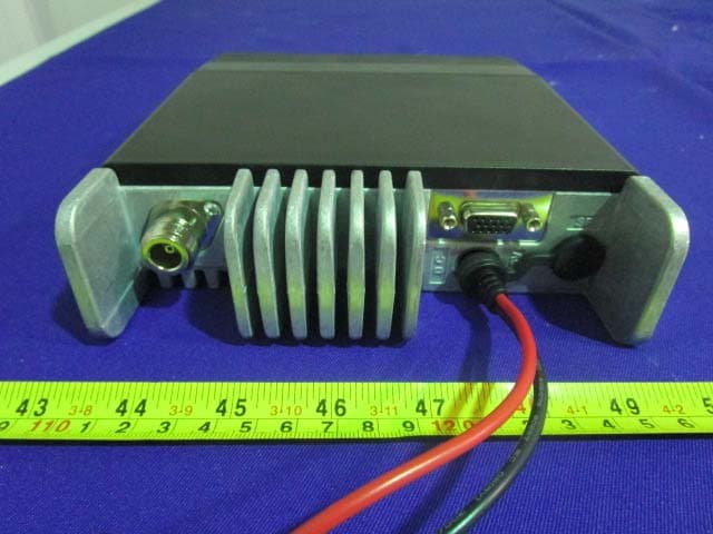
Y4GDM6000-2
May 26, 2015Mobile Radio
Equipment Class
TNB - Licensed Non-Broadcast Station Transmitter