Y4GDM6000-2Mobile Radio
SHENZHEN COVALUE COMMUNICATIONS CO., LTD.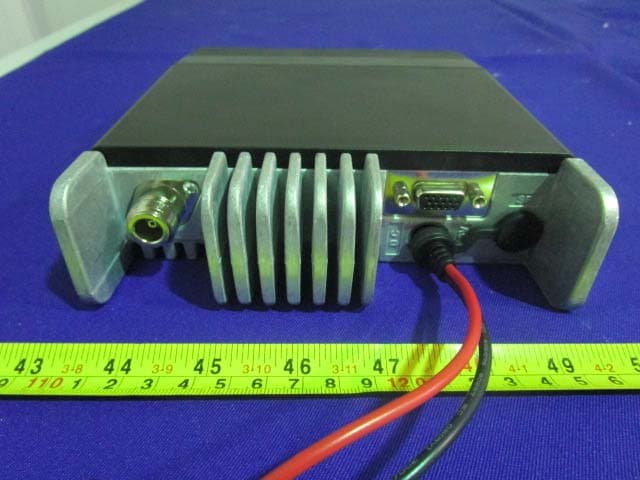
Click to zoom
Application Details
- Equipment Class
- TNB - Licensed Non-Broadcast Station Transmitter
- Date of Grant
- May 26, 2015
- Application Purpose
- Original Equipment
- Date of Application
- May 26, 2015
- Equipment Note
- Mobile Radio
- Frequency Range
- 406.10000000 - 470.00000000
- Country
- China
Documents & Files
Document Text
Text extracted from the exhibit documents filed with the FCC. Open a document above to read the original.
Users Manual
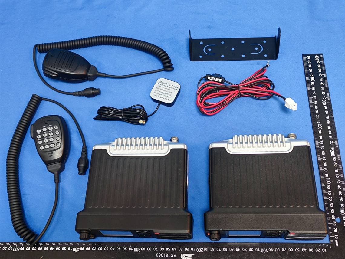
Instruction Manual DM6000-2 /DM6100-2 Mobile Radio Thank you for purchasing a COVALUE mobile radio. This simple to use radio adopts the latest advances in technology, providing reliable communication in today’s demanding communication environment. Notices to the User: When condensation occurs inside the transceiver: ·Condensation may occur inside the transceiver when the room is warmed using a heater on a cold day or when the transceiver is quickly moved from a cold location to a warm location. • When condensation occurs,the microcomputer and /or the transmit/receive circuits may become unstable,resulting in transceiver malfunction. • If this happens,turn OFF the transceiver and wait for a while. • When the condensed droplets disappear,the transceiver will function normally. Do not touch the metal surface of the transceiver while it is in use. Do not mount the transceiver such that the chassis can come in contact with skin. High temperatures may burn your skin. PRECAUTIONS Please observe the following precautions to prevent fire, personal injury, and/or transceiver damage: • Do not attempt to configure your transceiver while driving; it is simply too dangerous. • Be aware of local laws pertaining to the use of headphones/headsets while driving on public roads. If in doubt, do not wear headphones while mobiling. • Do not transmit with high output power for extended periods; the transceiver may overheat. • Do not modify the transceiver unless instructed by this manual or other COVALUE documentation. • Do not expose the transceiver to long periods of direct sunlight nor place it close to heating appliances. • Do not place the transceiver in excessively dusty,humid or wet areas, nor on unstable surfaces. • If an abnormal odor or smoke is detected coming from the transceiver, turn OFF the power immediately. Contact a COVALUE service station or your dealer. • This transceiver is designed for a 13.8 V power source. Never use a 24 V battery to power the transceiver. SUPPLIED ACCESSORIES After carefully unpacking the transceiver, identify the items listed in the table below. We recommend you keep the box and packaging for shipping. Accessory Qty Microphone (DTMF Mic) 1 DC power cable(Blade) 1 Fuse(Blade) 1 Mounting bracket 1 Screw set 1 Microphone hanger 1 Instruction manual 1 CHAPTER 1 PREPARATION MOBILE INSTALLATION To install the transceiver, select a safe, convenient location inside your vehicle that minimizes danger to your passengers and yourself while the vehicle is in motion. Consider installing the unit at an appropriate position so that knees or legs will not strike it during sudden braking of your vehicle. Try to pick a well ventilated location that is shielded from direct sunlight. 1 Install the mounting bracket in the vehicle using the supplied self-tapping screws (4), flat washers (4), and Spring washers (4). The bracket must be installed so that the 3 screw long hole positions on the side of the mounting bracket are towards The rear of the bracket. 2 Position the transceiver, then insert and tighten the supplied hexagon SEMS screws (4) and flat washers (4). Double check that all hardware is tightened to prevent vehicle vibration from loosening the bracket or transceiver. Determine the appropriate angle of the transceiver, using the 3 screw hole positions on the side of the mounting bracket. MOBILE OPERATION The vehicle batter y must have a nominal rating of 12 V. Never connect the transceiver to a 24 V batter y. Be sure to use a 12 V vehicle batter y that has sufficient current capacity. If the current to the transceiver is insufficient, the display may darken during transmission, or transmit output power may drop excessively. 1 Route the DC power cable supplied with the transceiver directly to the vehicle's batter y terminals using the shortest path from the transceiver. If using a noise filter, it should be installed with an insulator to prevent it from touching metal on the vehicle. We recommend you do not use the cigarette lighter socket as some cigarette lighter sockets introduce an unacceptable voltage drop. The entire length of the cable must be dressed so it is isolated from heat, moisture, and the engine secondar y (high voltage) ignition system/ cables. 2 After the cable is in place, wrap heat-resistant tape around the fuse holder to protect it from moisture and tie down the full run of cable. 3 To prevent the risk of short circuits, disconnect other wiring from the negative (–) batter y terminal before Connecting the transceiver. 4 Confirm the correct polarity of the connections, then attach the power cable to the batter y terminals; red connects to the positive (+) terminal and black connects to the negative (–) terminal. Use the full length of the cable without cutting off excess e v e n i f t h e c a b l e i s l o n g e r t h a n r e q u i r e d . I n particular,never remove the fuse holders from the Cable. 5 Reconnect any wiring removed from the negative terminal. 6 Connect the DC power cable to the transceiver's power supply connector. Press the connectors firmly together until the locking tab connectors firmly together until the locking tab clicks FIXED STATION OPERATION In order to use this transceiver for fixed station operation, you will need a separate 13.8 V DC power supply (not included). The recommended current capacity of your power supply is 14 A or more. 1 Connect the DC power cable to the regulated DC power supply and ensure that the polarities are correct (Red: positive, Black: negative). · Do not directly connect the transceiver to an AC outlet. ·Use the supplied DC power cable to connect the transceiver to a regulated power supply. ·Do not substitute a cable with smaller gauge wires. 2 Connect the transceiver's DC power connector to the connector on the DC power cable. Press the connectors firmly together until the locking tab Clicks Note: ◆ capabilities,we recommend using the power supply could output more than 23 A, 25% duty cycle. ◆ Before connecti…
Text truncated - open the document above for the full version.
Attestation Statements
SHENZHEN COVALUE COMMUNICATIONS CO., LTD. Add: 2/F., Bldg. 24, XiLi Industrial Park, No.119 Xinguang Rd, Xili, Nanshan, Shenzhen, China Tel: 0755-86345789 Fax: 0755-86345790 FCC Part90 Letter Date: 2015-05-13 FEDERAL COMMUNICATIONS COMMISSIONS Authorization and Evaluation Division 7435 Oakland Mills Road Columbia, MD 21046 Dear Sir/Madam, This equipment meets the requirements of the FCC Rules, Parts 90.203(e) and (g), as applicable. Programming of this products transmit frequencies can be performed ONLY by the manufacturer or by service or by maintenance personal. The operator can not program transmit frequencies using the equipment’s external operation controls. We hereby affirm that above equipment meets the FCC requirement of the Sec 90.203(j) (5) and is capable of transmitting data with a minimum data rate of 4800 bits per second per 6.25KHz channel bandwidth. Sincerely Yours, Signature: Shu, Chengtao Research &Development Department Manager
Cover Letter(s)
QA-FR-170-B SHENZHEN COVALUE COMMUNICATIONS CO., LTD. Add: 2/F., Bldg. 24, XiLi Industrial Park, No.119 Xinguang Rd, Xili, Nanshan, Shenzhen, China Tel: 0755-86345789 Fax: 0755-86345790 FCC Authorization Date: 2015-05-13 FEDERAL COMMUNICATIONS COMMISSION Authorization and Evaluation Division 7435 Oakland Mills Road Columbia, MD 21046 Subject: Agent Authorization To whom it may concern: We, SHENZHEN COVALUE COMMUNICATIONS CO., LTD., the undersigned, Hereby authorizes Bay Area Compliance Laboratories Corporation to act on its behalf in all matters relating to application for Equipment authorization, including the signing of all documents relating to these matters. All acts carried out by Bay Area Compliance Laboratories Corp. on our behalf shall have the same effect as our own action. We, the undersigned, hereby certify that we are not subject to a denial of federal benefits, that includes FCC benefits, pursuant to Section 5301 of the Anti-Drug Abuse Act of 1988, 21 U.S.C. 862. This authorization is valid until further written notice from the applicant. Sincerely Yours, Signature: Shu, Chengtao Research &Development Department Manager
Cover Letter(s)
SHENZHEN COVALUE COMMUNICATIONS CO., LTD. Add: 2/F., Bldg. 24, XiLi Industrial Park, No.119 Xinguang Rd, Xili, Nanshan, Shenzhen, China Tel: 0755-86345789 Fax: 0755-86345790 FCC Confidential Authorization Date: 2015-05-13 FEDERAL COMMUNICATIONS COMMISSION Authorization and Evaluation Division 7435 Oakland Mills Road Columbia, MD 21046 Confidentiality Request regarding application for certification of FCC ID: Y4GDM6000-2 Pursuant to Sections 0.457 and 0.459 of the Commission’s Rules, we hereby request confidential treatment of information accompanying this application as outlined below: Detailed Circuit Schematics of EUT--- (Long term) Block Diagram--- (Long term) Circuit Description--- (Long term) BOM--- (Long term) Tune up procedure--- (Long term) The above materials contain trade secrets and proprietary information not customarily released to the public. The public disclosure of these materials may be harmful to the applicant and provide unjustified benefits to its competitors. The applicant understands that pursuant to Section 0.457 of the Rules, disclosure of this application and all accompanying documentation will not be made before the date of the Grant for this application. Sincerely Yours, Signature: Shu, Chengtao Research &Development Department Manager
Cover Letter(s)
certification, SHENZHEN COVALUE COMMUNICATIONS CO., LTD. is requesting that the FCC lists the frequencies 400-470MHz, under FCC Rules Parts 22 and 90 on the FCC Grant. SHENZHEN COVALUE COMMUNICATIONS CO., LTD. Add: 2/F., Bldg. 24, XiLi Industrial Park, No.119 Xinguang Rd, Xili, Nanshan, Shenzhen, China Tel: 0755-86345789 Fax: 0755-86345790 Justification Letter Date: 2015-05-13 Federal Communications Commission Authorization & Evaluation Division 7435 Oakland Mills Road Colombia, Maryland 21046 Dear Sir/Madam, The Mobile Radio with FCC ID: Y4GDM6000-2 was designed to operate in the frequency bands 400-470MHz. To aid equipment authorization in other countries which accept the United States FCC Grant for SHENZHEN COVALUE COMMUNICATIONS CO., LTD. attests that the repeater will not be marketed to USA users with the frequency band which is not allowed by the rule part 22 and 90. Per the FCC’s KDB634817 guidance, as an alternative to listing the exact frequencies, we acknowledge that it’s a violation of the FCC Rules if this device operates on unauthorized frequencies. Sincerely, Signature: Shu, Chengtao Research &Development Department Manager Frequency Range(MHz) FCC Rule Part 400-406 MHz For Federal 406.1-450 MHz FCC Part 90 450-454 MHz FCC Part 90 454-455MHz FCC Part 22 456-460MHz FCC Part 22/ FCC Part 90 460-462.5375MHz FCC Part 90 462.7375-467.5375MHz FCC Part 90 467.7357-470MHz FCC Part 90
Cover Letter(s)
SHENZHEN COVALUE COMMUNICATIONS CO., LTD. Add: 2/F., Bldg. 24, XiLi Industrial Park, No.119 Xinguang Rd, Xili, Nanshan, Shenzhen, China Tel: 0755-86345789 Fax: 0755-86345790 DECLARATION OF SIMILARITY 2015-05-13 To: Dear Sir or Madam: We, SHENZHEN COVALUE COMMUNICATIONS CO., LTD., hereby declare that product: Mobile Radio, Model numbers: DM6000-2, DM6100-2 are electrically identical with the same electromagnetic emissions and electromagnetic compatibility characteristics. Model Number: is DM6100-2 electrically identical with the Model Number: DM6000-2 that was certified by BACL. Their difference is as following: 1. The horn dimension is different; 2. The screenprint font on the keypad is different. Please contact me should there be need for any additional clarification or information. Best Regards, Shu, Chengtao Research &Development Department Manager
External Photos
Page 1 of 8 EXHIBIT B - EUT EXTERNAL PHOTOGRAPHS DW6000-2 EUT– All View EUT–Top View Page 2 of 8 EUT– Bottom View EUT– Left Side View Page 3 of 8 EUT– Right Side View EUT–Front Side View Page 4 of 8 EUT– Rear Side View EUT – MicrophoneTop View Page 5 of 8 EUT – Microphone Bottom View DW6100-2 EUT –Top View Page 6 of 8 EUT– Bottom View EUT – Left Side View Page 7 of 8 EUT – Right Side View EUT –Front Side View Page 8 of 8 EUT– Rear Side View
ID Label/Location Info
EXHIBIT A - FCC ID LABELING AND LOCATION FCC ID Label FCC ID Label Location The label shown shall be permanently affixed at a conspicuous location on the device and be readily visible to the user at the time purchase (Labeling requirements per 2.925)
Internal Photos
Page 1 of 4 EXHIBIT C - EUT INTERNAL PHOTOGRAPHS EUT– Uncover View EUT– Uncover View Page 2 of 4 EUT– Filter View EUT– Main Board Top View Page 3 of 4 EUT–Main Board Bottom View EUT– Uncover View Page 4 of 4 EUT– Key Board BottomView
RF Exposure Info
Bay Area Compliance Laboratories Corp. (Dongguan) Report No.: RDG150505001-00 FCC Part 22 and 90 Page 8 of 39 FCC §2.1091- MAXIMUM PERMISSIBLE EXPOSURE (MPE) Applicable Standard According to 1.1307 (b)(1), 2.1091 systems operating under the provisions of this section shall be operated in a manner that ensures the public is not exposed to RF energy level in excess of the communication guidelines. Limits for Maximum Permissible Exposure (MPE) Limits for Occupational/Controlled Exposure Frequency Range (MHz) Electric Field Strength (E) (V/m) Magnetic Field Strength (H) (A/m) Power Density (S) (mW/cm 2 ) Averaging Time |E|, |H| or S (minutes) 0.3- 3.0 614 1.63 (100)* 6 3.0 - 30 1842/f 4.89/f (900/f 2 )* 6 30-300 61.4 0.163 1.0 6 300-1500 / / f/300 6 1500-100,000 / / 5 6 f = frequency in MHz; * = Plane-wave equivalent power density; MPE Calculation Predication of MPE limit at a given distance S = PG/4πR 2 Where: S = power density (in appropriate units, e.g. mW/cm 2 ); P = power input to the antenna (in appropriate units, e.g., mW); G = power gain of the antenna in the direction of interest relative to an isotropic radiator R = distance to the center of radiation of the antenna (appropriate units, e.g., cm); Bay Area Compliance Laboratories Corp. (Dongguan) Report No.: RDG150505001-00 FCC Part 22 and 90 Page 9 of 39 Calculated Data: Frequency The Max Target Conducted Output Power Antenna Cable Loss Typical Antenna Gain Distance Power Density Limit MHz mW dBm dB dBinumericcm mW/cm 2 mW/cm 2 435 45200 46.55 2.0 0 1.0 80 0.355 1.45 Note: The manufacturer does not specify an antenna to be used with this devicebut a typical installation has a gain up to 0dBi. Radio Exposure Statement: To comply with RF exposure requirements, a minimum separation distance of 80cm and with a 2dB cable loss is required between antenna and all public persons. Result: Compliant.
Test Report
Note: This test report is prepared for the customer shown above and for the device described herein. It may not be duplicated or used in part without prior written consent from Bay Area Compliance Laboratories Corp. (Dongguan). This report is valid only with a valid digital signature. The digital signature may be available only under the Adobe software above version 7.0. FCC PART 22 and 90 TEST REPORT For SHENZHEN COVALUE COMMUNICATIONS CO.,LTD. 2/F., Bldg. 24, XiLi Industrial Park, No.119 Xinguang Rd, Xili, Nanshan, Shenzhen, China FCC ID: Y4GDM6000-2 Report Type: Original Report Product Type: Mobile Radio Test En gineer: Dean Liu Re port Number: RDG150505001-00 Re port Date: 2015-05-25 Reviewed B y: Sula Huang RF Leader Test Laboratory: Bay Area Compliance Laboratories Corp. (Dongguan) No.69 Pulongcun, Puxinhu Industrial Zone, Tangxia, Dongguan, Guangdong, China Tel: +86-769-86858888 Fax: +86-769-86858891 www.baclcorp.com.cn Bay Area Compliance Laboratories Corp. (Dongguan) Report No.: RDG150505001-00 FCC Part 22 and 90 Page 2 of 39 TABLE OF CONTENTS GENERAL INFORMATION ....................................................................................................................................... 4 PRODUCT DESCRIPTION FOR EQUIPMENT UNDER TEST (EUT) ..................................................................................... 4 OBJECTIVE ................................................................................................................................................................... 4 RELATED SUBMITTAL(S)/GRANT(S) ............................................................................................................................. 4 TEST METHODOLOGY .................................................................................................................................................. 4 TEST FACILITY ............................................................................................................................................................. 4 SYSTEM TEST CONFIGURATION .......................................................................................................................... 5 DESCRIPTION OF TEST CONFIGURATION ...................................................................................................................... 5 SUPPORT EQUIPMENT LIST AND DETAILS .................................................................................................................... 5 BLOCK DIAGRAM OF TEST SETUP ................................................................................................................................ 6 SUMMARY OF TEST RESULTS ............................................................................................................................... 7 FCC §2.1091- MAXIMUM PERMISSIBLE EXPOSURE (MPE) ........................................................................... 8 APPLICABLE STANDARD .............................................................................................................................................. 8 FCC §2.1046 &§ 22.727 & §90.205- RF OUTPUT POWER .................................................................................. 10 APPLICABLE STANDARD ............................................................................................................................................ 10 TEST PROCEDURE ...................................................................................................................................................... 10 TEST EQUIPMENT LIST AND DETAILS ......................................................................................................................... 10 TEST DATA ................................................................................................................................................................ 10 FCC §2.1047 & §90.207 - MODULATION CHARACTERISTIC .......................................................................... 12 APPLICABLE STANDARD ............................................................................................................................................ 12 TEST PROCEDURE ...................................................................................................................................................... 12 TEST EQUIPMENT LIST AND DETAILS ......................................................................................................................... 12 TEST DATA ................................................................................................................................................................ 12 FCC §2.1049& §22.357 & § 22.731 &§90.209 & §90.210 – OCCUPIED BANDWIDTH & EMISSION MASK 16 APPLICABLE STANDARD ............................................................................................................................................ 16 TEST EQUIPMENT LIST AND DETAILS ......................................................................................................................... 17 TEST PROCEDURE ...................................................................................................................................................... 17 TEST DATA ................................................................................................................................................................ 17 FCC §2.1051& §22.861 & §90.210 - SPURIOUS EMISSIONS AT ANTENNA TERMINALS ........................... 25 APPLICABLE STANDARD ............................................................................................................................................ 25 TEST EQUIPMENT LIST AND DETAILS ......................................................................................................................... 25 TEST PROCEDURE ..............................................................................................................…
Text truncated - open the document above for the full version.
Test Setup Photos
Page 1 of 1 EXHIBIT D - TEST SETUP PHOTOGRAPHS Radiated Emission View (Below 1 GHz) Radiated Emission View (Above 1 GHz)
Contact Information
Applicant
Chengtao Shu(Engineer)
Test Firm
Bay Area Compliance Laboratories Corp. (Dongguan)John Chan
[email protected]86-769-86858888
Technical Specifications
| # | Rule Parts | Frequency Range | Power Output | Emission | Tolerance |
|---|---|---|---|---|---|
| 6 | 22,9 | 406.1 MHz - 470 MHz | 45 W | 9K59FXW | 0.5 ppm |
Other Applications from SHENZHEN COVALUE COMMUNICATIONS CO., LTD.
Y4GDM8000-2
Sep 11, 2024Mobile Radio
Equipment Class
DTS - Digital Transmission System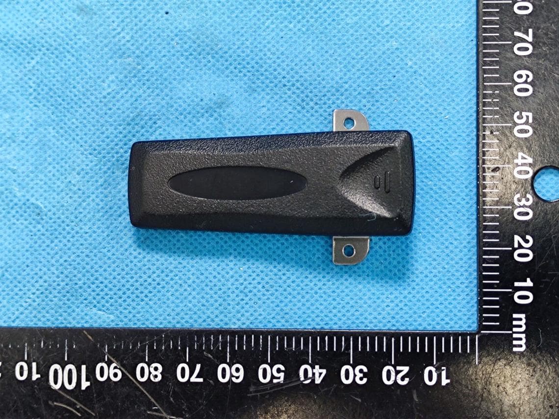
Y4GDR5810S-1
Jul 17, 2022Two Way Radio
Equipment Class
TNF - Licensed Non-Broadcast Transmitter Held to Face
Y4GDR5810-1
Mar 01, 2020Two Way Radio
Equipment Class
TNF - Licensed Non-Broadcast Transmitter Held to Face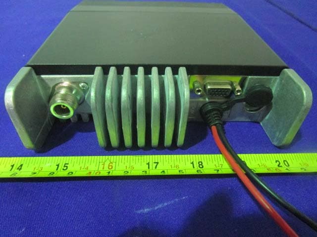
Y4GDM6000-1
Aug 20, 2015Mobile Radio
Equipment Class
TNB - Licensed Non-Broadcast Station Transmitter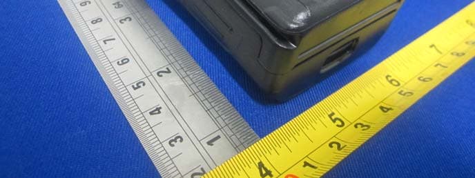
Y4GDR6000-1
Jul 30, 2014Two Way Radio
Equipment Class
TNF - Licensed Non-Broadcast Transmitter Held to Face