Y6MNCOM10Bluetooth hands-free kit
Nolangroup S.p.A.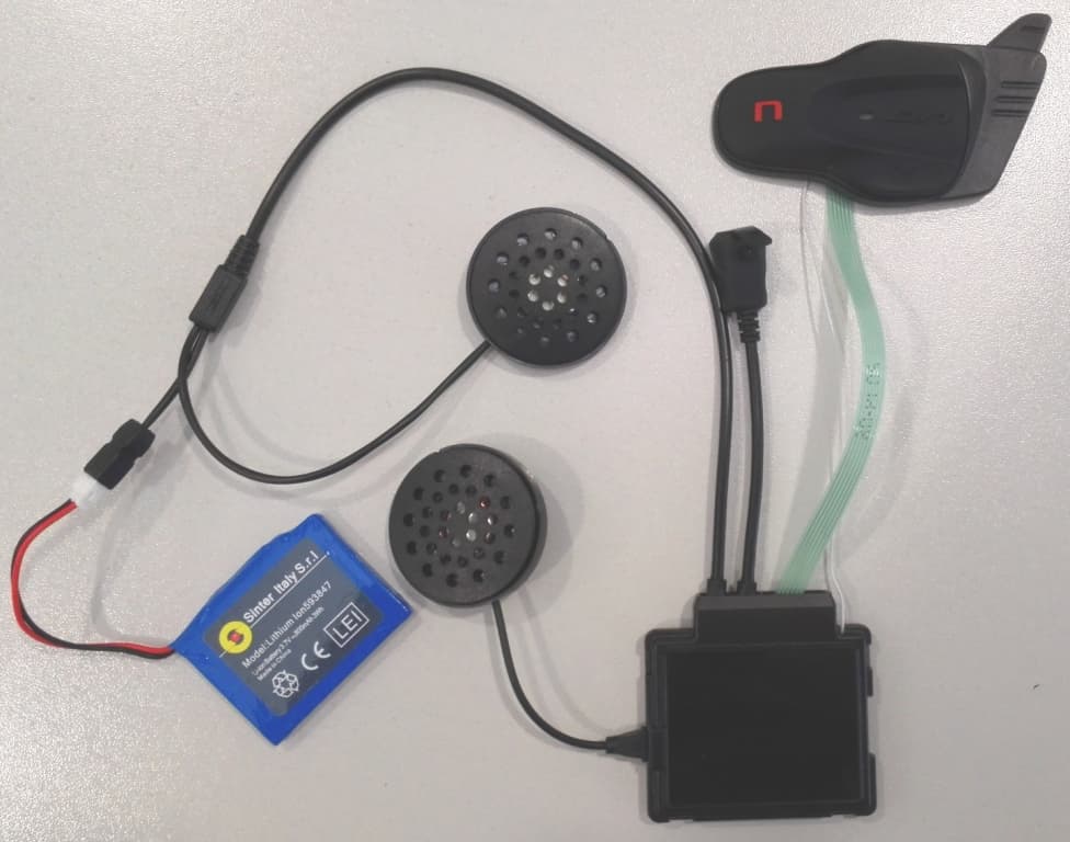
Click to zoom
Application Details
- Equipment Class
- DTS - Digital Transmission System
- Date of Grant
- Apr 22, 2015
- Application Purpose
- Original Equipment
- Date of Application
- Apr 21, 2015
- Equipment Note
- Bluetooth hands-free kit
- Frequency Range
- 2402.00000000 - 2480.00000000
- Company
- Nolangroup S.p.A.
- Country
- Italy
Documents & Files
Document Text
Text extracted from the exhibit documents filed with the FCC. Open a document above to read the original.
Users Manual
BX5 Used Accessories and cables 1) Used Accessories (Model, Type, S/N) N-COM USB BATTERY CHARGER (CARICABAT0006) Supplier: Shell Electronic Limited Model: S-TR-009L Type: Input:100~240V AC 50/60Hz Output:5VDC 0.5A N-COM BX4 / B1 v03 (BATTERIA00006) Supplier: Sinter Italy S.r.l. Model: Lithium Ion 593847 Rechargeable Type: 3,7V – 800mAh 2) Used Cables (Type, Length, Shield, Ferrites) LEFT AND RIGHT SPEAKER CABLE CABLASISX0002/ CABLASIDX0002 Supplier: P&H Tech Type: Left and right cables to connect the speaker and battery to the Bluetooth system. Lenght: mm 100 (CABLASISX0002) / mm 190 (CABLASIDX0002) CABLASISX0002: connected to the PCB using 14 pin connector mod. A0800HI-14P CABLASIDX0002: connected to the PCB using 14 pin connector mod. A0800HI-14P USB CABLE CAVUSB0000002 Supplier: LBT Technologies Shenzen Type: USB cable for connecting the battery charger to the micro USB plug. Lenght: mm 1500 Connection: micro USB plug (M) – to standard USB plug (M) MULTIMEDIA WIRE cod. R CAVAU00000012 (not provided on the packaging, available as accessory) Supplier: TPI Tripower Italia Type: Multimedia Wire for connecting audio devices to the X4 Bluetooth system. Lenght: 300 mm aprox Connection: micro USB (M) – to 3,5 mm 3 poles standard audio exit of Multimedia devices Other Multimedia Wires and Mobile Wires are available for the connection of additional Multimedia devices to the N-Com Basic Kit. Full list of compatible Mobile phones here: http://www.n- com.it/site/index.php?option=com_content&view=article&id=72&Itemid=108&lang=en&brandi d=1 Full list of compatible Multimedia devices here: http://www.n- com.it/site/index.php?option=com_content&view=article&id=74&Itemid=112&lang=en&brandi d=1
Users Manual
Firmware Version: 1.00 EN USER INSTRUCTIONS AND SAFETY Congratulations on your purchase of an N-Com product. N-Com BX5 was made using the most advanced technologies and the best materials. Long-running tests and thorough system development have allowed the highest audio quality to be achieved. For additional information about BX5, and to download high-definition instructions as well as the latest Firmware version, visit the website www.n-com.it REFERENCE STANDARDS The products of the N-Com line are in compliance with standards as per the table below: BX5 The Bluetooth system complies with the main safety requirements and other applicable provisions of Directive 99/5/CE, Directive 2002/95/CE, Directive 2011/65/CE, Directive 2002/96/CE Battery charger Directive 2006/95, 2004/108, 2002/95/CE, 2011/65/CE, 2002/96/CE, 2009/125/CE Battery Directive 2006/66 The Declarations of Compliance can be downloaded from the website www.n- com.it (Download section). FccID: XXXXX XXXXX Bluetooth is a registered trademark property of Bluetooth SIG, Inc Contents 1. WARNINGS AND SAFETY...................................................................................................................4 1.1.Road safety................................................................................................................................................................4 1.2.Switching on the system in safe environments.........................................................................................4 1.3.Interferences..............................................................................................................................................................4 1.4.Appropriate use.......................................................................................................................................................4 1.5.Qualified personnel................................................................................................................................................5 1.6.Accessories and batteries....................................................................................................................................5 1.7. Disposal.....................................................................................................................................................................6 2. CONTENT OF THE PACKAGING........................................................................................................7 3. INSTALLATION......................................................................................................................................8 3.1.Preliminary operations – Jet helmets or Flip-up helmets.....................................................................8 3.2.Preliminary operations – Full-face helmets.................................................................................................8 3.3.Installing the microphone – jet helmets or flip-up helmets..............................................................10 3.4.Installing the microphone – full-face helmets.........................................................................................10 3.5.Installing the battery and the right-hand side speaker.......................................................................11 3.6.Positioning the e-box..........................................................................................................................................12 3.7.Installing the adhesive keyboard...................................................................................................................13 4. REMOVING THE SYSTEM..................................................................................................................15 5. BASIC FUNCTIONS.............................................................................................................................16 5.1.N-Com Wizard and N-Com App....................................................................................................................16 5.1.Pairing up with Bluetooth devices.................................................................................................................16 6. MOBILE PHONE..................................................................................................................................17 6.1.Friend Number.......................................................................................................................................................17 6.2.Managing two mobile phones (or Bluetooth devices).........................................................................17 7. MUSIC VIA BLUETOOTH – A2DP BLUETOOTH PROTOCOLL....................................................18 8. MUSIC VIA CABLE..............................................................................................................................18 9. SATELLITE NAVIGATOR FOR MOTORCYCLES..............................................................................18 9.1.Navigators on Smartphone (Smart Navi System)...................................................................................19 10. FM RADIO............................................................................................................................................19 11. AUTO ON / OFF FUNCTION.............................................................................................................19 12. RIDER-PASSENGER INTERCOM.......................................................................................................19 12.1.Rider-Passenger intercom pairing up.......................................................................................................19 12.2.Rider-Passenger intercom function............................................................................................................19 13. BIKE TO BIKE INTERCOM.............................................................…
Text truncated - open the document above for the full version.
Users Manual
Firmware Version: 1.00 EN USER INSTRUCTIONS AND SAFETY Congratulations on your purchase of an N-Com product. N-Com BX5 was made using the most advanced technologies and the best materials. Long-running tests and thorough system development have allowed the highest audio quality to be achieved. For additional information about BX5, and to download high-definition instructions as well as the latest Firmware version, visit the website www.n-com.it REFERENCE STANDARDS The products of the N-Com line are in compliance with standards as per the table below: BX5 The Bluetooth system complies with the main safety requirements and other applicable provisions of Directive 99/5/CE, Directive 2009/65/EC, Directive 2011/65/CE, Directive 2012/19/EU Battery charger Directive 2006/95, 2004/108, 2009/65/EC, 2011/65/CE, 2012/19/EU, 2009/125/CE Battery Directive 2006/66/CE The Declarations of Compliance can be downloaded from the website www.n- com.it (Download section). FccID: Y6MNCOM10 N21550 Bluetooth is a registered trademark property of Bluetooth SIG, Inc. FOR USA AND CANADA MARKET ONLY: SPECIAL WARNING This device complies with part 15 of the FCC and Industry Canada Rules. Operation is subject to the following two conditions: (1) This device may not cause harmful interference, and (2) this device must accept any interference received, including interference that may cause undesired operation. Changes or modifications not expressly approved by the party responsible for compliance could void the user’s authority to operate the equipment. NOTE: The manufacturer is not responsible for any radio or TV interference caused by unauthorized modifications to this equipment. Such modifications could void the user’s authority to operate the equipment. This product has been tested and complies with the specifications for a Class B digital device, pursuant to Part 15 of the FCC Rules. These limits are designed to provide reasonable protection against harmful interference in a residential installation. This equipment generates, uses and can radiate radio frequency energy and, if not installed and used according to the instructions, may cause harmful interference to radio communications. However, there is no guarantee that interference will not occur in a particular installation. If this equipment does cause harmful interference to radio or television reception, which is found by turning the equipment off and on, the user is encouraged to try to correct the interference by one or more of the following measures: Reorient or relocate the receiving antenna Increase the separation between the equipment or devices Connect the equipment to an outlet other than the receiver’s Consult a dealer or an experienced radio/TV technician for assistance This model meets the government’s requirements for exposure to radio waves. Your wireless device is a radio transmitter and receiver. It is designed and manufactured not to exceed limits for exposure to radio frequency (RF) energy set by the Federal Communications Commission (FCC) of the U.S. Government and by the Canadian regulatory authorities. The exposure standard for wireless mobile devices employs a unit of measurement known as the Specific Absorption Rate, or SAR. The SAR limit set by the FCC and by the Canadian regulatory authorities is 1.6 W/kg.1 Tests for SAR are conducted using standard operating positions accepted by the FCC and by Industry Canada with the device transmitting at its highest certified power level in all tested frequency bands. The highest SAR value for this model device when tested for use at the ear is 0.099 W/kg. For Canada market only: This EUT is compliant with SAR for general population/uncontrolled exposure limits in IC RSS-102 and had been tested in accordance with the measurement methods and procedures specified in IEEE 1528. FccID: Y6MNCOM10 21550 Bluetooth is a registered trademark property of Bluetooth SIG, Inc.
Cover Letter(s)
BX5_antenna_information ---------- Antenna B X5 ---------- ANTENNA GAIN: 0.0 dBi Page 1
Cover Letter(s)
FCC, Request for non-disclosure Date: 16-Jul-10 RF_501, Issue 6 Page 1 of 1 Company Name: Nolangroup s.p.a. Address : via Terzi di S.Agata 2 City: Brembate di sopra, Italy Country: 24030 To: Telefication B.V., Dept. FCC TCB Edisonstraat 12A 6902 PK ZEVENAAR The Netherlands Subject: Request for confidentiality FCC ID: Y6MNCOM10 Reference number: ###### Dear FCC TCB, 1. Long-Term Confidentiality Pursuant to 47 CFR Section 0.459(a) & (b), we hereby requests non-disclosure and confidential treatment of the following materials submitted in support of FCC certification application: Bill(s) of Material Block Diagrams Operational Description Schematic Diagrams Tune-up Procedure Above materials contain secrets, proprietary and technical information, which would customarily be guarded from competitors under 47 CFR, section 0.457(d)(2). Disclosure or publication or any portion of this company confidential material to other parties could cause substantial competitive harm and provide unjustified benefits for competitors. 2. Short-Term Confidentiality (STC) Pursuant to Public Notice DA 04-1705 of the Commission’s policy, in order to comply with the marketing regulations in 47 CFR §2.803 and the importation rules in 47 CFR §2.1204, a pplicant hereby requests Short-Term Confidential treatment of the following materials (note 1): Internal Photos User’s Manual Test Set-up Photos External Photos Justification: Release of this information prior the availability of the product could cause substantial competitive harm and provide unjustified benefits to competitors. Planned Release Date STC: 180 Days from filing (notes 2, 3, 4, 5) Date: 03/23/2015 Name and signature of applicant: Imad Hjije Notes: 1) A document or type of document can only have ONE type of confidentiality! 2) Short-Term confidentiality is in principle for 45 days from date of grant; it can be extended max 3 times (total time 180 days max.)! 3) FCC must be informed when marketing begins earlier. 4) Release takes place automatically thus extension must be requested in time. Telefication does not remind you of this! 5) Request for extension or for release must be received by Telefication at least 7 days before date of actual marketing or before expiration of the STC period
ID Label/Location Info
N-Com BX5 – Label - Labels on the product Located on the external surface of the plastic Box containing the Bluetooth PCB. Labels on the packaging Located on the external pack of the Bluetooth device Labels on the instruction leaflet See page no.3 of instructions leaflet
Parts List/Tune Up Info
Redox S.r.l. SEMILAV. SMD SCHEDA NCOM EVO (MOD. BX5) NOLAN V.1.0 Description Qt y Note Reference Cod. Redox 10nF 0402 X7R ±10% 25 V COND. CER. SMD 1 C60 CC10n25S041 10pF 0402 C0G ±5% 50V COND. CER. SMD 1 C34 CC10p50S041 10uF 0603 X5R ±20% 6,3V COND. CER. SMD 4 C9,C10,C14,C74 CC10u6V3S061 15pF 0402 C0G ±5% 50V COND. CER. SMD 1 C54 CC15p50S041 1nF 0402 C0G ±5% 50V COND. CER. SMD 8 C3,C6,C31,C35,C36,C37,C38,C77 CC1n050S041 1uF 0402 X5R ±10% 6,3V COND. CER. SMD 18 C2,C4,C5,C15,C16,C21,C22,C24,C25,C26,C27,C32,C58,C59,C63,C65,C68,C70 CC1u06V3S041 22pF 0402 C0G ±5% 50V COND. CER. SMD 7 C33,C62,C64,C66,C67,C69,C71 CC22p50S041 2,2uF 0402 X5R ±20% 6,3V COND. CER. SMD 9 C39,C40,C41,C42,C44,C45,C47,C61,C83 CC2u26V3S041 47nF 0402 X7R ±10% 10V COND. CER. SMD 1 C13 CC47n10S041 4,7uF 0603 X5R ±10% 6,3V COND. CER. SMD 1 C82 CC4u76V3S061 100pF 0402 C0G 5% 50V COND. CER. SMD 3 C12,C55,C87 CCn1050S041 100nF 0402 X7R ±10% 16V COND. CER. SMD 16 C1,C11,C23,C28,C29,C30,C43,C48,C49,C51,C52,C53,C72,C73,C75,C84 CCu1016S041 470nF 0402 X5R ±10% 10V COND. CER. SMD 2 C46,C50 CCu4710S041 BAV70W SOT323 DIODO SWITCHING DOPPIO SMD 70V 200mA 1 D3 DFBAV70WS1 BAT60A SOD323 DIODO SCHOTTKY SMD 10V 3A 1,35W 1 D4 DHBAT60AS1 BZX585-B5V1 SC79 DIODO ZENER SMD 5,1V 0,3W 1 D2 DZBZX585B5S1 BZX84C6V2LT1 SOT23 DIODO ZENER SMD 6,2 V 0,3W 1 D1 DZBZX84C6VS1 LIS331DLH LGA-16 3-AXIS ACCELEROMETER SMD 1 U9 IALIS331DLS1 TPA6020A2 20-VQFN-EP AMPL. AUDIO STEREO SMD CL. AB 1 U2 IATPA6020AS1 74HC4066BQ DHVQFN14 QUAD BILATERAL SWITCH SMD 2 U1,U3 ID74HC4066S2 NC7WZU04P6X SC70-6 DUAL UNBUFFERED INVERTER SMD 1 U4 IDNC7WZU04S1 CSR8670C-IBBH-R VFBGA BT RADIO IC+AUDIO SYSTEM SMD 1 U6 IRCSR8670S1 TEA5991UK WLCSP FM STEREO RADIO IC CON RDS SMD 1 U5 IRTEA5991S2 MFI337S3959 USON8 iPOD AUTHENT. COPROCES. 2.0C SMD 1 U8 ISMFI337S3S1 LP2985IM5-3.3 SOT23-5 REG LDO SMD LOW NOISE V.NOTE 1 U7 IWLP2985IMS2 CONN. 14 PIN 0.8mm PITCH 90° WAFER-SMT MAS. SMD 3 J2,J4,J6 JC0V80M14S91 CONN. RF RECEPTACLE 0° SMD I-PEX MHF SERIES 1 J5 JRMHFM02S01 180nH 0603 ±5% INDUTT SMD 140mA Q25 LQW18ANR18J00D 1 L1 LAu18S061 4 x 600 OHM A 100 MHZ 1206 SMD ARRAY BEAD 2 L2,L3 LS600RS121 4.7uH ±20% 800mA 1008 MURATA LQM2HPN4R7MGCL 1 L5 LX4U7S105 BCX51 SOT89 TRANSISTOR PNP SMD 45V 1A 1 Q1 QBBCX51PS1 100 OHM 4x0402 DIL 5% RES SMD 63mW 50V SER. CRA04S 1 RR3 RD100RS041 10K 4x0402 DIL 5% RES. SMD 63mW 50V SERIE CRA04S 2 RR2,RR4 RD10K0S041 3,9K 4x0603 3,2x1,6mm DIL 5% RES. SMD 62,5mW 1 RR1 RD3K90S061 0 OHM 0402 RES. SMD 3 R29,R30,R39 RE0R00S041 100K 0402 5% RES. SMD 1 R26 RE100KS041 100 OHM 0402 5% RES. SMD 4 R12,R14,R17,R28 RE100RS041 10K 0402 5% RES. SMD 4 R2,R3,R5,R8 RE10K0S041 120 OHM 0402 5% RES. SMD 1 R21 RE120RS041 1K 0402 5% RES. SMD 2 R4,R7 RE1K00S041 22M 0402 5% RES. SMD 1 R19 RE22M0S041 22 OHM 0402 5% RES. SMD 1 R18 RE22R0S041 2,2K 0402 5% RES. SMD 2 R9,R11 RE2K20S041 330K 0402 5% RES. SMD 1 R20 RE330KS041 Page 1 of 2 Redox S.r.l. 33K 0402 5% RES. SMD 2 R1,R6 RE33K0S041 470K 0402 5% RES. SMD 1 R38 RE470KS041 0,22 OHM 0603 5% 1/10W RES. SMD 1 R40 RER220S061 0,39 OHM 1210 1% RES. SMD 1 R41 RER390S141 LFB182G45SG9A246 FILTRO PASSA-BANDA 2,45 GHz SMD 1 BP1 XF248S2 QUARZO 26MHz GSX-333/X 3.2x2.5x0.7mm SMD 10pF 1 Y2 XQ266S2 CM7V QUARZO 32,768KHz 3.3x1.6mm SMD ±20ppm 12,5pF 1 Y1 XQ323S4 C.S. SCHEDA NCOM EVO NOLAN VER. 1.0 Q. 3x4 1 PCS358V1P0 Page 2 of 2
RF Exposure Info
ANNEX for SAR Exemption Model: BX5 FCC ID: Y6MNCOM10 IC: 9455A- NCOM10 The N-COM BX5 device has a maximum output power of 9.75 dBm (9.4 mW) and is therefore exempted from SAR as per KDB 447498 D01 General RF Exposure Guidance v05r02. Yous sincerely, Imad Hjije
Test Report
Final Report on Internal PCB FCC ID Y6MNCOM10 IC: 9455A-NCOM10 MDE_REDOX_1404_FCCc acc. Title 47 CFR chapter I part 15 subpart C Report Reference: March 19, 2015Date: Test Laboratory: 7 layers AG Borsigstrasse 11 40880 Ratingen Germany Note: The following test results relate only to the devices specified in this document. This report shall not be reproduced in parts without the written approval of the test laboratory. 7 layers AG Aufsichtsratsvorsitzender Registergericht registered in: Borsigstrasse 11 Chairman of the Supervisory Board: Düsseldorf, HRB 44096 40880 Ratingen, Germany Peter Mertel USt-IdNr VAT No.: Phone: +49 (0) 2102 749 0 Vorstand Board: DE 203159652 Fax: +49 (0) 2102 749 350 Dr. H. Ansorge TAX No. 147/5869/0385 www.7Layers.com A Bureau Veritas Group Company Reference: MDE_REDOX_1404_FCCc acc. Title 47 CFR chapter I part 15 subpart C 2.3 OUT Features Features for OUT: Internal PCB FCC ID Y6MNCOM10 IC: 9455A-NCOM10 Allowed ValuesDesignationDescriptionSupported Value(s) Features for scope: FCC_v2 ACThe OUT is powered by or connected to AC Mains BTEUT supports Bluetooth data rate of 1 Mbps with GFSK modulation in the band 2400 MHz - 2483.5 MHz BTLESupport of Bluetooth Low Energy DCThe OUT is powered by or connected to DC EDR2EUT supports Bluetooth using data rate of 2 Mbps with PI/4 DQPSK modulation in the band 2400 MHz - 2483.5 MHz EDR3EUT supports Bluetooth using data rate of 3 Mbps with 8DPSK modulation in the band 2400 MHz - 2483.5 MHz TantCtemporary antenna connector, which may be only built-in for testing, designed as an example part of the equipment 2.4 Setups used for Testing For each setup a relation is given to determine if and which samples and auxiliary equipment is used. The left side list all OUT samples and the right side lists all auxiliary equipment for the given setup. Sample No.Sample DescriptionAE No.AE Description Setup No. List of OUT samplesList of auxiliary equipment Setup_AC01 (Setup for conducted measurments) ac01Conducted sampleSample: Page 4 of 23 Reference: MDE_REDOX_1404_FCCc acc. Title 47 CFR chapter I part 15 subpart C 3Results 3.1 General Available at the test laboratory. The results of the inspection are described on the following pages, where 'Conformity' or 'Passed' means that the certification criteria were verified and that the tested device is conform to the applied standard. In cases where 'Declaration' is printed, the required documents are available in the manufacturers product documentation. In cases where 'not applicable' is printed, the test case requirements are not relevant to the specific equipment implementation. Documentation of tested devices: Interpretation of the test results: 1. All tests are performed under environmental conditions within the requirements of the specifications. Environmental conditions are available at the laboratory. 2. The device is an internal PCB inside a hands-free kit containing a BT and BTLE Transceiver operating in the 2.4 GHz ISM band. 3. This report focuses only on the BTLE part. Results of "radiated spurious emissions" and "Conducted emissions (AC power line)" are included in the report "MDE_REDOX_1404_FCCb". Note: 3.2 List of the Applicable Body (Body for Scope: FCC_v2) DesignationDescription Subpart C - Intentional Radiators; 15.247 Operation within the bands 902-928 MHz, 2400-2483.5 MHz, and 5725-5850 MHz. FCC47CFRChIPART15c247RADIO FREQUENCY DEVICES 3.3 List of Test Specification Test Specification:FCC part 2 and 15 Version10-1-13 Edition Title:PART 2 - GENERAL RULES AND REGULATIONS PART 15 - RADIO FREQUENCY DEVICES Page 5 of 23 Reference: MDE_REDOX_1404_FCCc acc. Title 47 CFR chapter I part 15 subpart C 3.4 Summary Test Case Identifier / Name SetupDate of TestResultTest (condition)Ref. Lab 15c.10 Power density §15.247 (e) 15c.10; Frequency = Low/Mid/High2014/10/02Setup_AC01Lab 1Passed 15c.11 6dB Bandwidth §15.247 (a) (2) 15c.11; Frequency = Low/Mid/High2014/10/02Setup_AC01Lab 1Passed 15c.4 Peak power output §15.247 (b) (1) 15c.4; Mode = Bluetooth Low Energy2014/10/02Setup_AC01Lab 1Passed 15c.5 Spurious RF conducted emissions §15.247 (d) 15c.5; Mode = Bluetooth Low Energy2014/10/02Setup_AC01Lab 1Passed 15c.6 Band edge compliance §15.247 (d) 15c.6; Band edge compliance Summary2014/10/02Setup_AC01Lab 1Passed Page 6 of 23 Reference: MDE_REDOX_1404_FCCc acc. Title 47 CFR chapter I part 15 subpart C 3.5 Detailed Results 3.5.1 15c.10 Power density §15.247 (e) Test: 15c.10; Frequency = Low/Mid/High Result:Passed Setup No.:Setup_AC01 Date of Test:2014/10/02 16:38 Body:FCC47CFRChIPART15c247RADIO FREQUENCY DEVICES Test Specification:FCC part 2 and 15 Detailed Results: lowest frequency mid frequency highest frequency 2402 MHz2441 MHz2480 MHz -8.54-7.54-7.42 per 1 MHzper 1 MHzper 1 MHz TEST CONDITIONSMaximum Spectral Power Density (RMS) (including antenna gain and correction factor) Bluetooth Low Energy (GFSK) 3.5.2 15c.11 6dB Bandwidth §15.247 (a) (2) Test: 15c.11; Frequency = Low/Mid/High Result:Passed Setup No.:Setup_AC01 Date of Test:2014/10/02 16:27 Body:FCC47CFRChIPART15c247RADIO FREQUENCY DEVICES Test Specification:FCC part 2 and 15 Detailed Results: ModulationFrequency6dB Bandwidth KHz 2402 MHz 707.7 2426 MHz 2440 MHz 712 2480 MHz 716.4 GFSK Page 7 of 23 Reference: MDE_REDOX_1404_FCCc acc. Title 47 CFR chapter I part 15 subpart C 3.5.3 15c.4 Peak power output §15.247 (b) (1) Test: 15c.4; Mode = Bluetooth Low Energy Result:Passed Setup No.:Setup_AC01 Date of Test:2014/10/02 16:45 Body:FCC47CFRChIPART15c247RADIO FREQUENCY DEVICES Test Specification:FCC part 2 and 15 Detailed Results: Modulation Conditions Output Power (dBm) Output Power (mW) Output Power (dBm) Output Power (mW) Output Power (dBm) Output Power (mW) GFSK TN, VN7.445.558.346.828.356.84 mW EIRP Conducted8.35dBm6.84mW 0 Antena Gain (dBi) 2440 MHz2480 MHz Conducted Transmitter Power 2402 MHz Max Conducted Output Power (FSK Modulation) 8.35dBm6.84 Page 8 of 23 Reference: MDE_REDOX_1404_FCCc acc. Title 47 CFR chapter I part 15 subpart C…
Text truncated - open the document above for the full version.
Test Setup Photos
Test Laboratory: 7Layers AG Borsigstrasse 11 40880 Ratingen Germany Note: The following test results relate only to the devices specified in this document. This report shall not be reproduced in parts without the written approval of the test laboratory. 7 layers AG Aufsichtsratsvorsitzender h Registergerichth registered in: Borsigstrasse 11 Chairman of the Supervisory Board: Düsseldorf, HRB 44096 40880 Ratingen, Germany Peter Mertel USt-IdNr h VAT No.: Phone: +49 (0) 2102 749 0 Vorstandh Board: DE 203159652 Fax: +49 (0) 2102 749 350 Dr. H. Ansorge TAX No. 147/5869/0385 www.7Layers.com A Bureau Veritas Group Company Photo Report on Test Setups Report Reference: MDE_REDOX_1404_FCC_Photo_Setups Test report Reference: MDE_REDOX_1404_FCC_Photo_Setups Page 2 of 7 Photo 1: Test setup for radiated measurements (Enclosure, below 30 MHz, intentional radiator §15) Test report Reference: MDE_REDOX_1404_FCC_Photo_Setups Page 3 of 7 Photo 2: Test setup for radiated measurements (Enclosure, semi-anechoic chamber, 30 MHz to 1 GHz, intentional radiator §15) Test report Reference: MDE_REDOX_1404_FCC_Photo_Setups Page 4 of 7 Photo 3: Test setup for radiated measurements (Enclosure, fully-anechoic chamber, 1-18 (15) GHz intentional radiator §15 Test report Reference: MDE_REDOX_1404_FCC_Photo_Setups Page 5 of 7 Photo 4: Test setup for radiated measurements (Enclosure, fully-anechoic chamber, 18-25 GHz, intentional radiator § 15.247) Test report Reference: MDE_REDOX_1404_FCC_Photo_Setups Page 6 of 7 Photo 5: Test setup for conducted measurements (computer peripheral setup, EUT supplied by USB-cable from computer, charging mode, unintentional radiator §15) Test report Reference: MDE_REDOX_1404_FCC_Photo_Setups Page 7 of 7 Photo 6: Test setup for radiated measurements (computer peripheral setup, EUT supplied by external DC power to enable USB data transfer to computer, unintentional radiator §15)
Contact Information
Applicant
Claudio Corollo
Technical Contact
Non-Technical Contact
Nolangroup s.p.a.Claudio Corollo
[email protected]39 035602285
Test Firm
7layers AGRobert Machulec
Technical Specifications
| # | Rule Parts | Frequency Range | Power Output |
|---|---|---|---|
| 1 | 15C | 2.40 GHz - 2.48 GHz | 7.00 mW |
Other Applications from Nolangroup S.p.A.
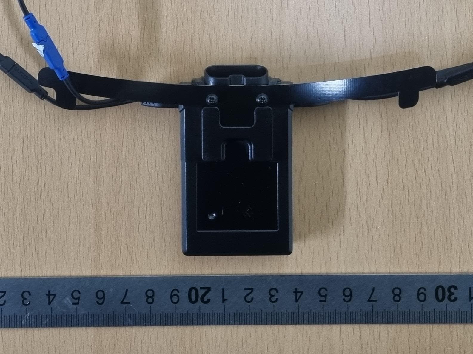
Y6MNCOM26
Jan 16, 2024N-Com M951 R
Equipment Class
DTS - Digital Transmission System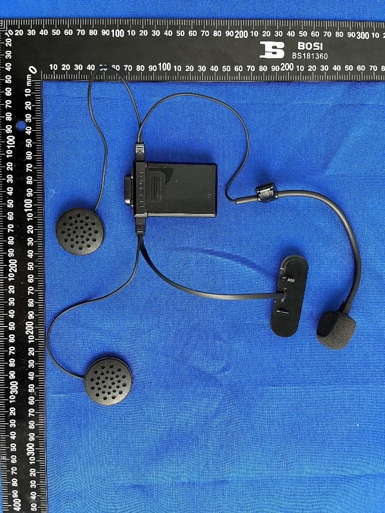
Y6MNCOM25
Jan 01, 2023N-Com B101 R
Equipment Class
DSS - Part 15 Spread Spectrum Transmitter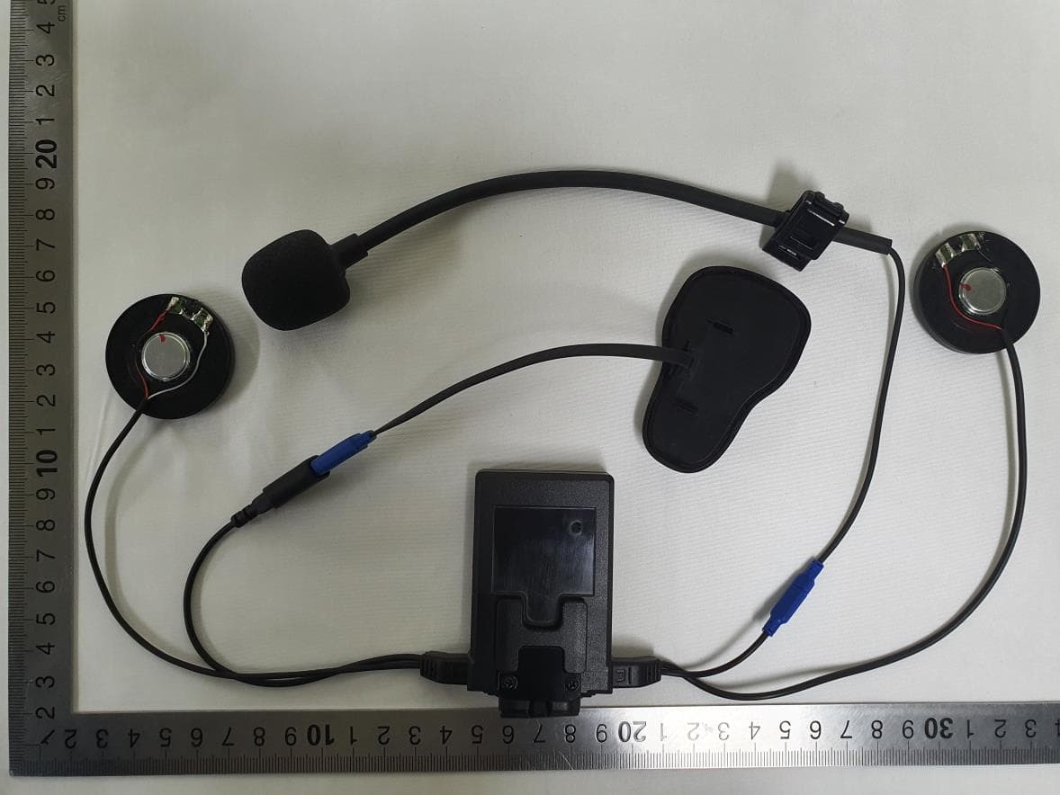
Y6MNCOM23
Nov 08, 2022N-Com B602 R
Equipment Class
DSS - Part 15 Spread Spectrum Transmitter
Y6MNCOM24
Nov 07, 2022N-Com B602 X
Equipment Class
DTS - Digital Transmission System
Y6MNCOM22
Oct 14, 2020N-Com B902 X
Equipment Class
DSS - Part 15 Spread Spectrum Transmitter