Y6MNCOM3Motorcycle helmet communication system with Bluetooth transceiver
Nolangroup S.p.A.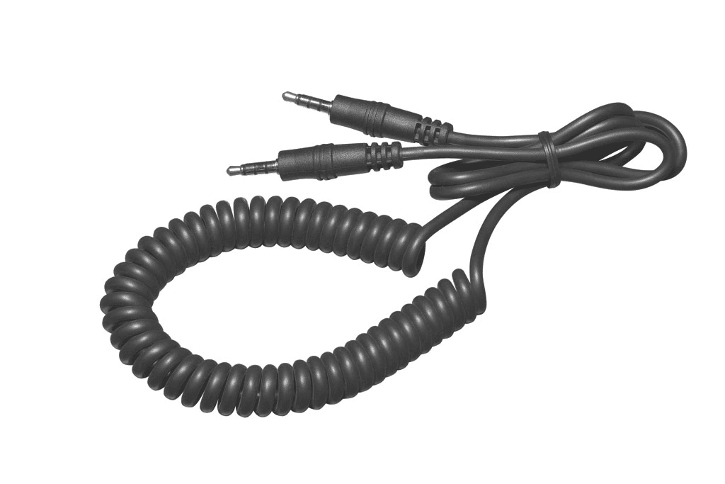
Click to zoom
Application Details
- Equipment Class
- DSS - Part 15 Spread Spectrum Transmitter
- Date of Grant
- Aug 01, 2011
- Application Purpose
- Original Equipment
- Date of Application
- Aug 01, 2011
- Equipment Note
- Motorcycle helmet communication system with Bluetooth transceiver
- Frequency Range
- 2402.00000000 - 2480.00000000
- Company
- Nolangroup S.p.A.
- Country
- Italy
Documents & Files
Document Text
Text extracted from the exhibit documents filed with the FCC. Open a document above to read the original.
Users Manual
EN USER INSTRUCTIONS AND SAFETY Congratulations on your purc hase of an N-Com product. N-Com Bluetooth Kit3 was made using the most advanced technologies and the best materials. Long-running tests and thorough system development ha ve allowed the highest audio quality to be achieved. For additional information about Bluetooth Kit3, and to download high-definition instructions as well as the latest Firmware version, visit the website www.n-com.it 3 Contents 1. WARNINGS AND SAFETY _______ 5 1.1.Reference standards _________ 5 1.2.Road safety ________________ 5 1.3.Switching on the system in safe environments____________________ 6 1.4.Interferences _______________ 6 1.5.Appropriate use _____________ 6 1.6.Qualified personnel __________ 7 1.7.Accessories and batteries______ 7 1.8.Disposal ___________________ 8 2. CONTENT OF THE PACKAGING __ 9 3. INSTALLATION _____________ 10 4. SYSTEM CHARACTERISTICS ___ 11 4.1.Basic functions _____________ 12 4.2.System menu ______________ 12 4.3.N-Com Wizard _____________ 13 5. PAIRING UP BLUETOOTH DEVICES__________________ 14 5.1.Affiliation reset function ______ 15 6. MOBILE PHONE FUNCTIONS ___ 15 7. GPS SATELLITE NAVIGATOR FUNCTIONS _______________ 16 8. STEREO FM RADIO __________ 17 9. BLUETOOTH A2DP MUSIC PLAYER ___________________ 18 10. AUDIO DEVICES WITH CABLE CONNECTION_______________19 11. INTERCOM MODE BETWEEN TWO HELMETS __________________20 11.1. Intercom affiliation ______20 11.2. Intercom function _______21 11.3. Bike-to-Bike intercom ____21 12. INTERCOM VIA CABLE ________22 13. BATTERY ___________________23 13.1. Battery discharged signal _23 14. SUMMARY TABLE OF CONTROLS_24 15. LIMITED WARRANTY __________27 15.1. Warranty coverage ______27 15.2. Exclusions and limitations of the coverage __________________27 15.3. Validity of this limited warranty _____________________28 15.4. Procedure for the forwarding of claims ______________28 15.5. Product identification _____30 16. WARRANTY REGISTRATION FORM _____________________35 4 FOR USA MARKET ONLY: SPECIAL WARNING This device complies with part 15 of the FCC Rules. Operation is subject to the following two conditions: (1) This device may not cause harmful interference, and (2) this device must accept any interference received, including interference that may cause undesired operation. Changes or modifications no t expressly approved by the party responsible for compliance could void the user’s authority to operate the equipment. NOTE: The manufacturer is not responsible fo r any radio or TV interference caused by unauthorized modifications to this equipm ent. Such modifications could void the user’s authority to operate the equipment. This product has been tested and complies wi th the specifications for a Class B digital device, pursuant to Part 15 of the FCC Rule s. These limits are designed to provide reasonable protection against harmful interference in a residential installation. This equipment generates, uses and can radiat e radio frequency energy and, if not installed and used according to the instructions, may cause harmful interference to radio communications. However, there is no guarantee that interference will not occur in a particular installation. If this equipment does cause harmful interfe rence to radio or television reception, which is found by turning the equipment off and on, the user is encouraged to try to correct the interference by one or more of the following measures: • Reorient or relocate the receiving antenna • Increase the separation between the equipment or devices • Connect the equipment to an outlet other than the receiver’s • Consult a dealer or an experienced radio/TV technician for assistance FccID: Y6MNCOM3 N21550 5 1. WARNINGS AND SAFETY Read this User Manual carefully, as well as the User Manuals for other N-Com kits that you will be using with the N-Com Bluetooth kit3. Read the simple rules listed below. Failure to comply with these rules may lead to dangerous situations. Caution : The product cannot be used in offi cial or non-official competitions, motordromes, circuits, raci ng tracks and the like. Caution : Installation of the N-Com Bluetooth kit3 system results in a weight increase of approximately 60g, which is added to the weight of the helmet and of the other accessories. Warning : The electronic components of the N-Com system mounted inside the helmet are not waterproof. Consequently, make sure the inside of the helmet, including the comfort padding, does not ge t wet in order to avoid damage to the system. If it does, remove the N-Com system and the helmet comfort padding and let it air dry. Discon nect the battery connector and let it dry as well. 1.1. Reference standards The products of the N-Com line are in compliance with standards as per the table below: Bluetooth kit3 The Bluetooth system complies with the main safety requirements and other applicab le provisions of Directive 99/5/CE. FccID: Y6MNCOM3 N21550 Bluetooth is a registered trademark property of Bluetooth SIG, Inc. 1.2. Road safety Always obey all Traffic Regulations in forc e. While riding the motorcycle, your hands should always be engaged in actually ridi ng the vehicle. Any operation to the N-Com system must be carried out with the vehicle stopped. Specifically: 6 • Set your cell phone on automatic answer (see the cell phone instructions to do this). • If your cell phone is not equipped with this function, first stop your vehicle in a safe area, in compliance with Traffic Regulations and then answer the call. • Do not make any calls while riding. St op your vehicle in a safe place in compliance with Traffic Regulations, and then make the call. • Adjust the volume so that it does not cause a disturbance or distraction while riding and at the same time allows you to distinctively hear background noises. • Do not operate your cell phone or other devices connected to N-Com while riding your motorcycle. • In all cases, obey the Traffic Regulations and remember that riding the mot…
Text truncated - open the document above for the full version.
Cover Letter(s)
7 layers AG Borsigstr.11 40880 Ratingen Germany Attn: Reviewing Engineer Federal Communications Commission 7435 Oakland Mills Road Columbia, MD 21046 CONFIDENTIALITY REQUEST FOR “NCOM3” FCC-ID: Y6MNCOM3 Sirs, In accordance with FCC Rule Section 0.457 and 0.459 of CFR 47, 7 layers AG (authorized by Opticos srl) hereby requests the following documentation as Long-term confidential: - Schematic diagrams - Block diagrams - Operational Description Short-term confidential (until 01. August 2011): - Internal Photos - Test Setup Photos - User Manual These documents contain detailed system and equipment description and related information about the product, which Opticos srl considers to be proprietary. This information should never get into the possession of competitors, which would be harmful for our business. Do not hesitate to contact me if you have any additional questions. Carsten Steinroeder Ratingen, 11/05/2011
External Photos
1) Used Accessories (Model, Type, S/N) N-COM BATTERY CHARGER Model: FY0901000 Type: 110/240v – 50/60 Hz N-COM BATTERY Model: Lithium Ion593847 Type: 3,7V – 800mAh 2) Used Cables (Type, Length, Shield, Ferrites) USB CABLE Type: USB cable for connecting the helmet Basic Kit with the PC Lenght: 300 mm Connection: 3,5 mm 4 poles – to standard USB plug MULTIMEDIA WIRE cod. X (not provided on the packaging, available as accessory) Type: Multimedia Wire for connecting audio devices to the N-Com Basic Kit on the helmet Lenght: 300 mm aprox Connection: 3,5 mm 4 poles – to 3,5 mm 3 poles standard audio exit of Multimedia devices INTERCOM WIRE (not provided on the packaging, available as accessory) Type: intercom Wire for connecting two N-Com Basic Kit placed on two different helmets (pilot and passenger) Lenght: 300 mm aprox Connection: 3,5 mm 4 poles – to 2,5 mm 4 poles output jack of the pilot’ Basic Kit on the helmet. Other Multimedia Wires and Mobile Wires are available for the connection of additional Multimedia devices to the N-Com Basic Kit. Full list of compatible Mobile phones here: http://www.n- com.it/site/index.php?option=com_content&view=article&id=72&Itemid=108&lang=en&brandi d=1 Full list of compatible Multimedia devices here: http://www.n- com.it/site/index.php?option=com_content&view=article&id=74&Itemid=112&lang=en&brandi d=1
External Photos
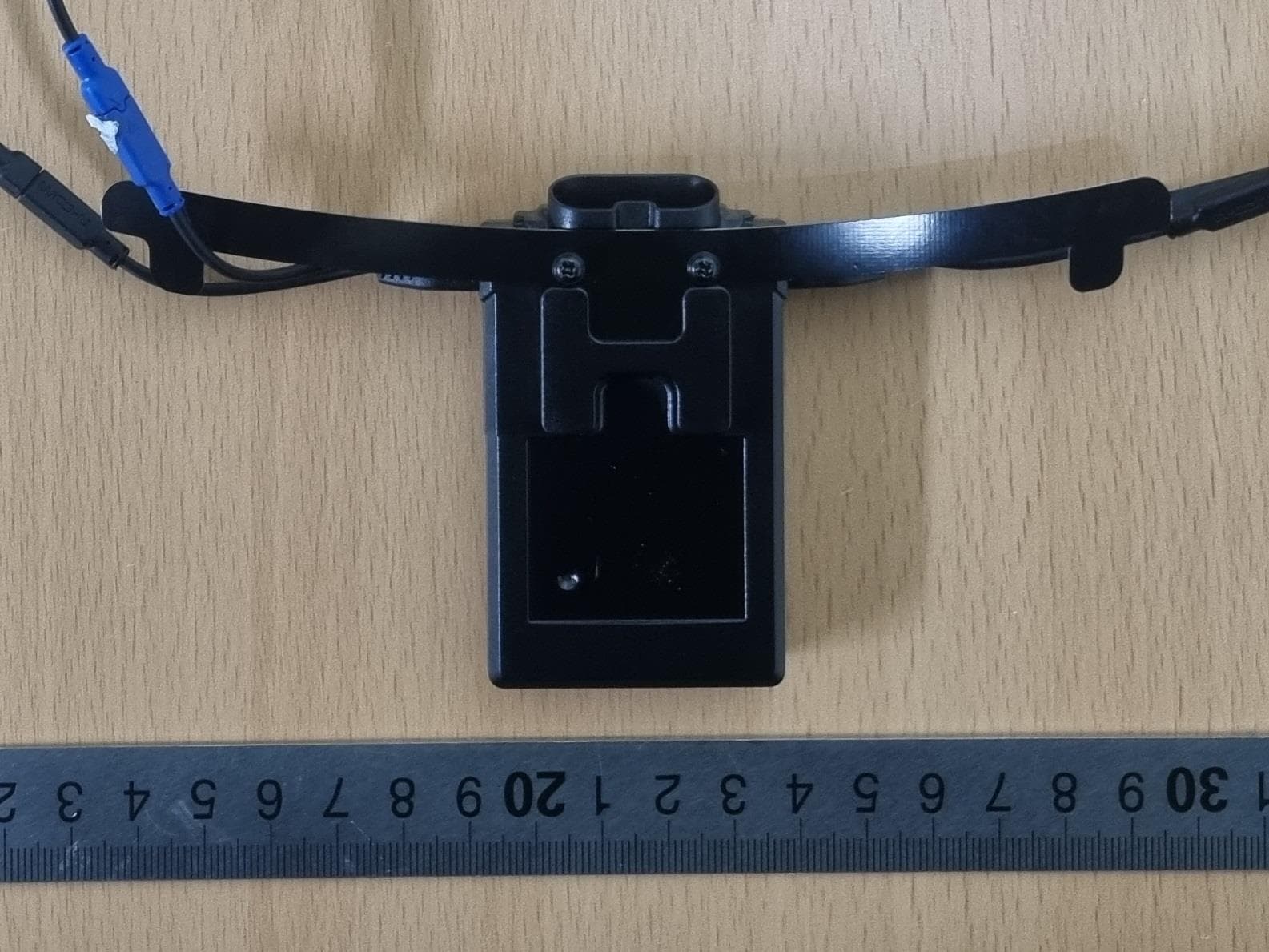
EXTERNAL PHOTOS NCOM3 – Bluetooth module NCOM3 with Nolan N90
Internal Photos
INTERNAL PHOTOS
RF Exposure Info
DAT-P-152/98-01 SAR_Report_7layers_6620_838_FCC_BT_CalData_ncom3 Appendix for the Report Dosimetric Assessment of the Portable Device Redox ncom3 (FCC ID: Y6MNCOM3) According to the FCC Requirements Calibration Data February 21, 2011 IMST GmbH Carl-Friedrich-Gauß-Str. 2 D-47475 Kamp-Lintfort Customer 7layers AG Borsigstrasse 11 D-40880 Ratingen Dasy_Report_FCC_DECT_1900_1.1.doc/22.05.2006/CH DAT-P-152/98-01 Cal_D2450V2_SN709_1209 Page 1 of 8 _ Calibration_Certificate_Dipole_V1.0/01.08.2009/ABo Calibration Certificate Certificate No: Cal_D2450V2_SN709_1209 Object: D2450V2 SN: 709 Date of Calibration: December 09, 2009 Next Calibration: December 2011 Object Condition: In Tolerance Calibration Equipment used: Test Equipment Serial Number Last calibration Calibrated by Next calibration Powermeter E4416A GB41050414 Dec 08 Agilent Techn. (ISO/IEC 17025, 1-1784162174-1) Dec 10 Power Sensor E9301H US40010212 Dec 08 Agilent Techn. (ISO/IEC 17025, 1-1784041195-1) Dec 10 Powermeter E4417A GB41050441 Dec 08 Agilent Techn. (ISO/IEC 17025, 1-1674038198-1) Dec 10 Power Sensor E9301A MY41495584 Dec 08 Agilent Techn. (ISO/IEC 17025, 1-1784041307-1) Dec 10 Network Analyzer E5071C MY46103220 Aug 09 Rohde& Schwarz (14967-DKD-00201- 2009-08) Aug 10 Reference Probe EX3DV4 SN 3536 Sep 09 SPEAG, No EX- 3536_Sep09 Sep 10 DAE4 SN 661 Sep 09 SPEAG, No DAE4- 661_Sep09 Sep 10 Cal_D2450V2_SN709_1209 Page 2 of 8 Calibration is performed according the following standards: IEEE 1528-2003 "IEEE Recommended Practice for Determining the Peak Spatial - Averaged Specific Absorption Rate (SAR) in the Human Head from Wireless Communication Devices: Measurement Technique", December 2003 IEC 62209-1 "Procedure to measure the Specific Absorption Rate (SAR) for hand - held devices used in close proximity to the ear (frequency range of 300 MHz to 3GHz)", February 2005 Federal Communications Commission Office of Engineering & Technologies (FCCOET) "Evaluating Compliance wit FCC Guidelines for Human Exposure to Radiofrequency Electromagnetic Fields; Additional Information for Evaluating Compliance of Mobile and Portable Devices with FCC Limits for Human Exposure to Radiofrequency Emissions", Supplement C (Edition 01-01) to Bulletin 65 Additional Documentation: DASY 4 System Handbook prepared by: reviewed by: Alexander Rahn André van den Bosch test engineer quality assurance engineer 08/ABo Cal_D2450V2_SN709_1209 Page 3 of 8 Measurement Conditions DASY Version: Dasy 4; V4.7 Phantom: SAM Phantom 1341 Distance Dipole Center – TSL: 10mm With spacer Zoom Scan res. dx, dy, dz = 5mm Frequency: 2450 MHz ± 1MHz Head TSL Parameters Temperature Permittivity Conductivity Nominal Head TSL Parameters 22.0 39.20 1.80 Measured Head TSL Parameters 22.0 40.2 ± 6% 1.84 S/m ± 6% SAR result with Head TSL Averaged over 1g SAR measured 250mW input power 13.60 mW/g SAR normalized normalized to 1W 54.40 mW/g SAR for nominal Head TSL parameters normalized to 1W 54.58 mW/g ± 16.5 % k=2) Averaged over 10g SAR measured 250mW input power 6.16 mW/g SAR normalized normalized to 1W 24.64 mW/g SAR for nominal Head TSL parameters normalized to 1W 24.78 mW/g ± 16.5 % (k=2) Cal_D2450V2_SN709_1209 Page 4 of 8 Body TSL Parameters Temperature Permittivity Conductivity Nominal Body TSL Parameters 22.0 52.70 1.95 Measured Body TSL Parameters 22.0 51.70 ± 6% 2.00 S/m ± 6% SAR result with Body TSL Averaged over 1g SAR measured 250mW input power 13.20 mW/g SAR normalized normalized to 1W 52.80 mW/g SAR for nominal Body TSL parameters normalized to 1W 51.76 mW/g ± 16.5 % (k=2) Averaged over 10g SAR measured 250mW input power 6.01 mW/ g SAR normalized normalized to 1W 24.04 mW/g SAR for nominal Body TSL parameters normalized to 1W 23.81 mW/g ± 16.5 % (k=2) General Antenna Parmeters Antenna Parameters with Head TSL Impedance, transformed to feed point 49.7 jΩ - 1.23 jΩ Return Loss -37.97 dB Antenna Parameter with Body TSL Impedance, transformed to feed point 50.8 jΩ - 1.27 jΩ Return Loss -36.55 dB After long term use with 100W radiated power, only a slight warming of the dipole near the feedpoint can be measured. The dipole is made of standard semigrid coaxial cable. The center conductor of the feeding line is directly connected to the second arm of the dipole. The antenna is therefore short-circuited for DC signals. Additional EUT Data Manufactured by: SPEAG Manufactured on: July 5, 2002 Cal_D2450V2_SN709_1209 Page 5 of 8 SAR result with Head TSL Test Laboratory: Imst GmbH, DASY Yellow (II); File Name: 091209_y_3536.da4 DUT: Dipole 2450 MHz SN: 709; Type: D2450V2; Serial: D2450V2 - SN:709 Program Name: System Performance Check at 2450 MHz Communication System: CW; Frequency: 2450 MHz;Duty Cycle: 1:1 Medium parameters used: f = 2450 MHz; σ = 1.84 mho/m; ε r = 40.2; ρ = 1000 kg/m 3 Phantom section: Flat Section DASY4 Configuration: - Probe: EX3DV4 - SN3536; ConvF(7.59, 7.59, 7.59); Calibrated: 18.09.2009 - Sensor-Surface: 4mm (Mechanical Surface Detection) - Electronics: DAE4 Sn631; Calibrated: 14.09.2009 - Phantom: SAM Glycol 1340; Type: QD 000 P40 CB; Serial: TP-1340 - Measurement SW: DASY4, V4.7 Build 80; Postprocessing SW: SEMCAD, V1.8 Build 186 d=10mm, Pin=250mW/Area Scan (7x7x1): Measurement grid: dx=10mm, dy=10mm Maximum value of SAR (measured) = 15.3 mW/g d=10mm, Pin=250mW/Zoom Scan (7x7x7)/Cube 0: Measurement grid: dx=5mm, dy=5mm, dz=5mm Reference Value = 91.4 V/m; Power Drift = 0.016 dB Peak SAR (extrapolated) = 29.6 W/kg SAR(1 g) = 13.6 mW/g; SAR(10 g) = 6.16 mW/g Maximum value of SAR (measured) = 15.2 mW/g Cal_D2450V2_SN709_1209 Page 6 of 8 SAR result with Body TSL Test Laboratory: Imst GmbH, DASY Yellow (II); File Name: 081209_y_3536.da4 DUT: Dipole 2450 MHz SN: 709; Type: D2450V2; Serial: D2450V2 - SN:709 Program Name: System Performance Check at 2450 MHz Communication System: CW; Frequency: 2450 MHz;Duty Cycle: 1:1 Medium parameters used: f = 2450 MHz; σ = 2 mho/m; ε r = 51.7; ρ = 1000 kg/m 3 Phantom section: Flat Section DASY4 Configuration: - Probe: EX3DV4 - SN3536…
Text truncated - open the document above for the full version.
RF Exposure Info
DAT-P-152/98-01 SAR_Report_7layers_6620_838_FCC_BT_ncom3_1 Page 1 of 27 Report Dosimetric Assessment of the Portable Device Redox ncom3 (FCC ID: Y6MNCOM3) (IC 9455A-NCOM3) According to the FCC Requirements February 21, 2011 IMST GmbH Carl-Friedrich-Gauß-Str. 2 D-47475 Kamp-Lintfort Dasy_Report_FCC_DECT_1900_1.1.doc/22.05.2006/CH Customer 7layers AG Borsigstrasse 11 D-40880 Ratingen The test results only relate to the items tested. This report shall not be reproduced except in full without the written approval of the testing laboratory. SAR_Report_7layers_6620_838_FCC_BT_ncom3_1 Page 2 of 27 Executive Summary The ncom3 is a new cordless Bluetooth headset (Portable Device) from Redox operating in the 2450 MHz frequency range. The device is designed to be used in a motorcycle helmet and operates with an integrated antenna. The objective of the measurements done by IMST was the dosimetric assessment of one headset, ncom3. For the test a special test software was used to set the device to one specific channel at maximum output power. The positioning of the equipment during the tests was similar to the position of the equipment in the motorcycle helmet, relative to the human head. The examinations have been carried out with the dosimetric assessment system „DASY4“. The measurements were made according to the Supplement C to OET Bulletin 65 of the Federal Communications Commission (FCC) Guidelines [OET 65] for evaluating compliance of mobile and portable devices with FCC limits for human exposure (general population) to radiofrequency emissions. All measurements have been performed in accordance to the recommendations given by SPEAG. The Redox ncom3 cordless Bluetooth headset (FCC ID: Y6MNCOM3) is in compliance with the Federal Communications Commission (FCC) Guidelines [OET 65] for uncontrolled exposure. Since the intended use position is head configuration, body worn assessment was not conducted. Maximum SAR 1g = 0.190 W/kg (cheek left, Channel 39) prepared by: ........................................... reviewed by: ..................................... Alexander Rahn André van den Bosch Dasy_Report_FCC_DECT_1900_1.1.doc/22.05.2006/CH test engineer quality assurance engineer SAR_Report_7layers_6620_838_FCC_BT_ncom3_1 Page 3 of 27 Dasy_Report_FCC_DECT_1900_1.1.doc/22.05.2006/CH Table of Contents 1 SUBJECT OF INVESTIGATION .................................................................................................................... 4 2 THE IEEE STANDARD C95.1-1999 AND THE FCC EXPOSURE CRITERIA ....................................... 4 2.1 DISTINCTION BETWEEN EXPOSED POPULATION, DURATION OF EXPOSURE AND FREQUENCIES ........... 4 2.2 DISTINCTION BETWEEN MAXIMUM PERMISSIBLE EXPOSURE AND SAR LIMITS ....................................... 5 2.3 SAR LIMIT .................................................................................................................................................. 5 3 THE FCC MEASUREMENT PROCEDURE ................................................................................................. 6 3.1 GENERAL REQUIREMENTS......................................................................................................................... 6 3.2 DEVICE OPERATING NEXT TO A PERSON’S EAR ....................................................................................... 6 4 BODY-WORN CONFIGURATIONS .............................................................................................................. 9 4.1 POC (PTT) POSITION .............................................................................................................................. 10 4.2 PHANTOM REQUIREMENTS ...................................................................................................................... 10 4.3 TEST TO BE PERFORMED ......................................................................................................................... 10 5 THE MEASUREMENT SYSTEM ................................................................................................................. 10 5.1 PHANTOM ................................................................................................................................................. 12 5.2 PROBE ...................................................................................................................................................... 12 5.3 MEASUREMENT PROCEDURE .................................................................................................................. 13 5.4 UNCERTAINTY ASSESSMENT ................................................................................................................... 14 6 SAR RESULTS ............................................................................................................................................... 15 7 EVALUATION ................................................................................................................................................. 15 8 APPENDIX ....................................................................................................................................................... 16 8.1 ADMINISTRATIVE DATA ............................................................................................................................ 16 8.2 DEVICE UNDER TEST AND TEST CONDITIONS ......................................................................................... 16 8.3 TISSUE RECIPES ...................................................................................................................................... 16 8.4 MATERIAL PARAMETERS ......................................................................................................................... 17 8.5 SIMPLIFIED PERFORMANCE CHECKING ................................................................................................... 17 8.6 ENVIRONMENT .....................................................…
Text truncated - open the document above for the full version.
RF Exposure Info
DAT-P-152/98-01 SAR_Report_7layers_6620_838_FCC_BT_SAR Plots_ncom3_1 Page 1 of 5 Appendix for the Report Dosimetric Assessment of the Portable Device Redox ncom3 (FCC ID: Y6MNCOM3) (IC 9455A-NCOM3) According to the FCC Requirements SAR Distribution Plots February 21, 2011 IMST GmbH Carl-Friedrich-Gauß-Str. 2 D-47475 Kamp-Lintfort Dasy_Report_FCC_DECT_1900_1.1.doc/22.05.2006/CH Customer 7layers AG Borsigstrasse 11 D-40880 Ratingen The test results only relate to the items tested. This report shall not be reproduced except in full without the written approval of the testing laboratory. SAR_Report_7layers_6620_838_FCC_BT_SAR Plots_ncom3_1 Page 2 of 5 dasy_report_fcc_DECT_1900_plots_1.0.doc/110.05.2006/ABo Table of Contents 1 SAR DISTRIBUTION PLOTS, HEAD MEASUREMENTS ......................................................................... 3 2 SAR Z-AXIS SCANS (VALIDATION) ........................................................................................................... 5 3 SAR Z-AXIS SCANS (MEASUREMENTS) .................................................................................................. 5 SAR_Report_7layers_6620_838_FCC_BT_SAR Plots_ncom3_1 Page 3 of 5 1 SAR Distribution Plots, Head Measurements Test Laboratory: Imst GmbH, DASY Yellow (II); File Name: ncom_yblm_1.da4 DUT: mcom; Type: mcom3; Program Name: left side Communication System: Bluetooth; Frequency: 2441 MHz;Duty Cycle: 1:1 Medium parameters used: f = 2441 MHz; σ = 1.86 mho/m; ε r = 37.4; ρ = 1000 kg/m 3 Phantom section: Left Section DASY4 Configuration: - Probe: EX3DV4 - SN3536; ConvF(7.26, 7.26, 7.26); Calibrated: 16.09.2010 - Sensor-Surface: 4mm (Mechanical Surface Detection) - Electronics: DAE4 Sn631; Calibrated: 17.09.2010 - Phantom: SAM Glycol 1340; Type: QD 000 P40 CB; Serial: TP-1340 - Measurement SW: DASY4, V4.7 Build 80; Postprocessing SW: SEMCAD, V1.8 Build 186 Left/Area Scan (16x21x1): Measurement grid: dx=10mm, dy=10mm Maximum value of SAR (measured) = 0.205 mW/g Left/Zoom Scan (7x7x7)/Cube 0: Measurement grid: dx=5mm, dy=5mm, dz=5mm Reference Value = 1.62 V/m; Power Drift = -0.136 dB Peak SAR (extrapolated) = 0.387 W/kg SAR(1 g) = 0.190 mW/g; SAR(10 g) = 0.091 mW/g Maximum value of SAR (measured) = 0.211 mW/g dasy_report_fcc_DECT_1900_plots_1.0.doc/110.05.2006/ABo Fig. 1: SAR distribution for Bluetooth, channel 39, cheek position, left side of head (February 18, 2011; Ambient Temperature: 22.3°C; Liquid Temperature: 22.0°C). SAR_Report_7layers_6620_838_FCC_BT_SAR Plots_ncom3_1 Page 4 of 5 Test Laboratory: Imst GmbH, DASY Yellow (II); File Name: ncom_ybrm_1.da4 DUT: mcom; Type: mcom3; Program Name: right side Communication System: Bluetooth; Frequency: 2441 MHz;Duty Cycle: 1:1 Medium parameters used: f = 2441 MHz; σ = 1.86 mho/m; ε r = 37.4; ρ = 1000 kg/m 3 Phantom section: Right Section DASY4 Configuration: - Probe: EX3DV4 - SN3536; ConvF(7.26, 7.26, 7.26); Calibrated: 16.09.2010 - Sensor-Surface: 4mm (Mechanical Surface Detection) - Electronics: DAE4 Sn631; Calibrated: 17.09.2010 - Phantom: SAM Glycol 1340; Type: QD 000 P40 CB; Serial: TP-1340 - Measurement SW: DASY4, V4.7 Build 80; Postprocessing SW: SEMCAD, V1.8 Build 186 right/Area Scan (9x13x1): Measurement grid: dx=10mm, dy=10mm Maximum value of SAR (measured) = 0.002 mW/g right/Zoom Scan (7x7x7)/Cube 0: Measurement grid: dx=5mm, dy=5mm, dz=5mm Reference Value = 1.00 V/m; Power Drift = 0.159 dB Peak SAR (extrapolated) = 0.002 W/kg SAR(1 g) = NA mW/g; SAR(10 g) = NA mW/g dasy_report_fcc_DECT_1900_plots_1.0.doc/110.05.2006/ABo Fig. 2: SAR distribution for Bluetooth, channel 39, cheek position, right side of head (February 18, 2011; Ambient Temperature: 22.3°C; Liquid Temperature: 22.0°C). SAR_Report_7layers_6620_838_FCC_BT_SAR Plots_ncom3_1 Page 5 of 5 2 SAR Z-axis Scans (Validation) Fig. 3: SAR versus liquid depth, 2450 MHz, head (February 18, 2011; Ambient Temperature: 22.3° C; Liquid Temperature : 22.0° C). 3 SAR Z-axis Scans (Measurements) The following picture shows the plot of SAR versus liquid depth for the worst case values. dasy_report_fcc_DECT_1900_plots_1.0.doc/110.05.2006/ABo Fig. 4: SAR versus liquid depth, head: Bluetooth, channel 39, cheek position, left side of head (February 18, 2011; Ambient Temperature: 22.3° C; Liquid Temperature : 22.0° C).
Test Report
REDOX S.R.L. VIA MANODORI 7. 42124 REGGIO EMILIA. ITALY TEL. 0522 512099 FAX 0522 921967 P.I. 01499110359 e.mail: [email protected] BLUETOOTH ANTENNA COD. MEAN008 Manufacturer: Redox s.r.l. Type: Dipole Nominal Gain: 0dBi Max Gain: 1.2dBi Cable: 0.4D Single shield PFA cable – lenght 10mm
Test Report
7Layers AGAufsichtsratsvorsitzenderhRegistergerichth registered in: Borsigstrasse 11Chairman of the Supervisory Board:Düsseldorf, HRB 44096 40880 Ratingen, GermanyMarkus BeckerUSt-IdNr h VAT No.: Phone: +49 (0) 2102 749 0Vorstandh Board:DE 203159652 Fax: +49 (0) 2102 749 350Dr. H.-J. MeckelburgTAX No. 147/5869/0385 www.7Layers.comWilfried Klassmann InterLab is a registered trademark of 7 layers AG FCC Measurement/Technical Report on Bluetooth transceiver N-COM Bluetooth Kit 3 including NCOM3 Bluetooth Module Report Reference:MDE_REDOX_1001_FCCc Test Laboratory: 7 layers AG Borsigstrasse 11 40880 Ratingen Germany email: [email protected] DGA-PL-192/99-02 Note: The following test results relate only to the devices specified in this document. This report shall not be reproduced in parts without the written approval of the testing laboratory. Test report Reference: MDE_REDOX_1001_FCCcPage 2 of 91 Table of Contents 0Summary3 0.1Technical Report Summary3 0.2Measurement Summary4 1Administrative Data7 1.1Testing Laboratory7 1.2Project Data7 1.3Applicant Data7 1.4Manufacturer Data7 2Test object Data8 2.1General EUT Description8 2.2EUT Main components9 2.3Ancillary Equipment9 2.4Auxiliary Equipment9 2.5EUT Setups10 2.6Operating Modes11 2.7Product labelling11 3Test Results12 3.1Conducted emissions (AC power line)12 3.2Occupied bandwidth14 3.3Peak power output17 3.4Spurious RF conducted emissions20 3.5Spurious radiated emissions23 3.6Band edge compliance29 3.7Dwell time33 3.8Channel separation35 3.9Number of hopping frequencies37 4Test Equipment38 5Photo Report45 6Setup Drawings45 7FCC and IC Correlation of measurement requirements46 8Annex measurement plots47 8.1AC Mains conducted47 8.2Occupied bandwidth48 8.3Peak power output57 8.4Band edge compliance conducted and Spurious RF conducted emissions66 8.5Band edge compliance radiated84 8.6Radiated emissions (f < 30 MHz)87 8.7Dwell time89 8.8Channel separation90 8.9Number of hopping frequencies91 Test report Reference: MDE_REDOX_1001_FCCcPage 3 of 91 0 Summary 0.1 Technical Report Summary Type of Authorization Certification for an Intentional Radiator (Frequency Hopping Spread Spectrum). Applicable FCC Rules Prepared in accordance with the requirements of FCC Rules and Regulations as listed in 47 CFR Ch.1 Parts 2 (10-1-10 Edition) and 15 (10-1-10 Edition). The following subparts are applicable to the results in this test report. Part 2, Subpart J - Equipment Authorization Procedures, Certification Part 15, Subpart C – Intentional Radiators § 15.201 Equipment authorization requirement § 15.207 Conducted limits § 15.209 Radiated emission limits; general requirements § 15.247 Operation within the bands 902-928 MHz, 2400-2483.5 MHz and 5725-5850 MHz Note: The tests were selected and performed with reference to the FCC Public Notice DA 00- 705, released March 30, 2000. Instead of applying ANSI C63.4-1992 which is referenced in the FCC Public Note, the newer ANSI C63.4-2009 is applied. Summary Test Results: The EUT complied with all performed tests as listed in chapter 0.2 Measurement Summary. Test report Reference: MDE_REDOX_1001_FCCcPage 4 of 91 0.2 Measurement Summary FCC Part 15, Subpart C§ 15.207 Conducted emissions (AC power line) The measurement was performed according to ANSI C63.42009 OP-ModeSetupPortFinal Result op-mode 2Setup_a02AC Port (power line)passed 1) FCC Part 15, Subpart C§ 15.247 (a) (1) Occupied bandwidth The measurement was performed according to FCC § 15.3110-1-10 Edition OP-ModeSetupPortFinal Result op-mode 1Setup_b01Temp ant.connectorpassed op-mode 2Setup_b01Temp ant.connectorpassed op-mode 3Setup_b01Temp ant.connectorpassed op-mode 6Setup_b01Temp ant.connectorpassed op-mode 7Setup_b01Temp ant.connectorpassed op-mode 8Setup_b01Temp ant.connectorpassed op-mode 10Setup_b01Temp ant.connectorpassed op-mode 11Setup_b01Temp ant.connectorpassed op-mode 12Setup_b01Temp ant.connectorpassed FCC Part 15, Subpart C§ 15.247 (b) (1) Peak power output The measurement was performed according to FCC § 15.3110-1-10 Edition OP-ModeSetupPortFinal Result op-mode 1Setup_b01Temp ant.connectorpassed op-mode 2Setup_b01Temp ant.connectorpassed op-mode 3Setup_b01Temp ant.connectorpassed op-mode 6Setup_b01Temp ant.connectorpassed op-mode 7Setup_b01Temp ant.connectorpassed op-mode 8Setup_b01Temp ant.connectorpassed op-mode 10Setup_b01Temp ant.connectorpassed op-mode 11Setup_b01Temp ant.connectorpassed op-mode 12Setup_b01Temp ant.connectorpassed FCC Part 15, Subpart C§ 15.247 (d) Spurious RF conducted emissions The measurement was performed according to FCC § 15.3110-1-10 Edition OP-ModeSetupPortFinal Result op-mode 1Setup_b01Temp ant.connectorpassed op-mode 2Setup_b01Temp ant.connectorpassed op-mode 3Setup_b01Temp ant.connectorpassed op-mode 6Setup_b01Temp ant.connectorpassed op-mode 7Setup_b01Temp ant.connectorpassed op-mode 8Setup_b01Temp ant.connectorpassed op-mode 10Setup_b01Temp ant.connectorpassed op-mode 11Setup_b01Temp ant.connectorpassed op-mode 12Setup_b01Temp ant.connectorpassed Test report Reference: MDE_REDOX_1001_FCCcPage 5 of 91 FCC…
Text truncated - open the document above for the full version.
Contact Information
Applicant
Claudio Corollo
Test Firm
7layers AGRobert Machulec
Technical Specifications
| # | Rule Parts | Frequency Range | Power Output |
|---|---|---|---|
| 1 | 15C | 2.40 GHz - 2.48 GHz | 59.00 mW |
Other Applications from Nolangroup S.p.A.
Y6MNCOM26
Jan 16, 2024N-Com M951 R
Equipment Class
DTS - Digital Transmission System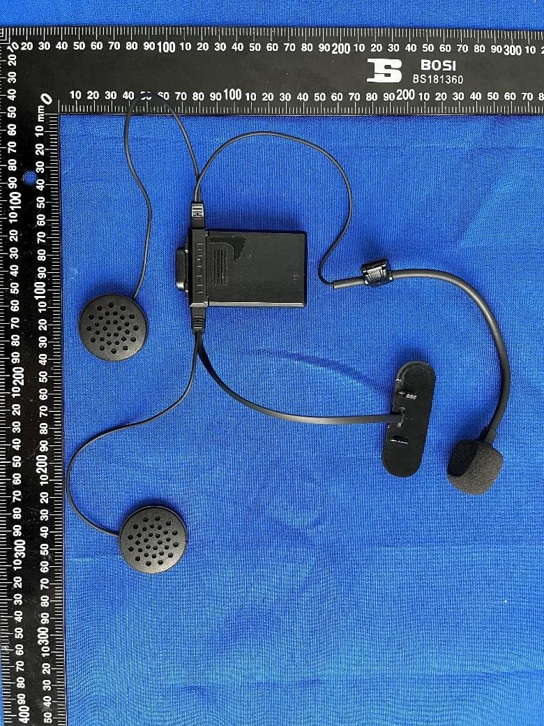
Y6MNCOM25
Jan 01, 2023N-Com B101 R
Equipment Class
DSS - Part 15 Spread Spectrum Transmitter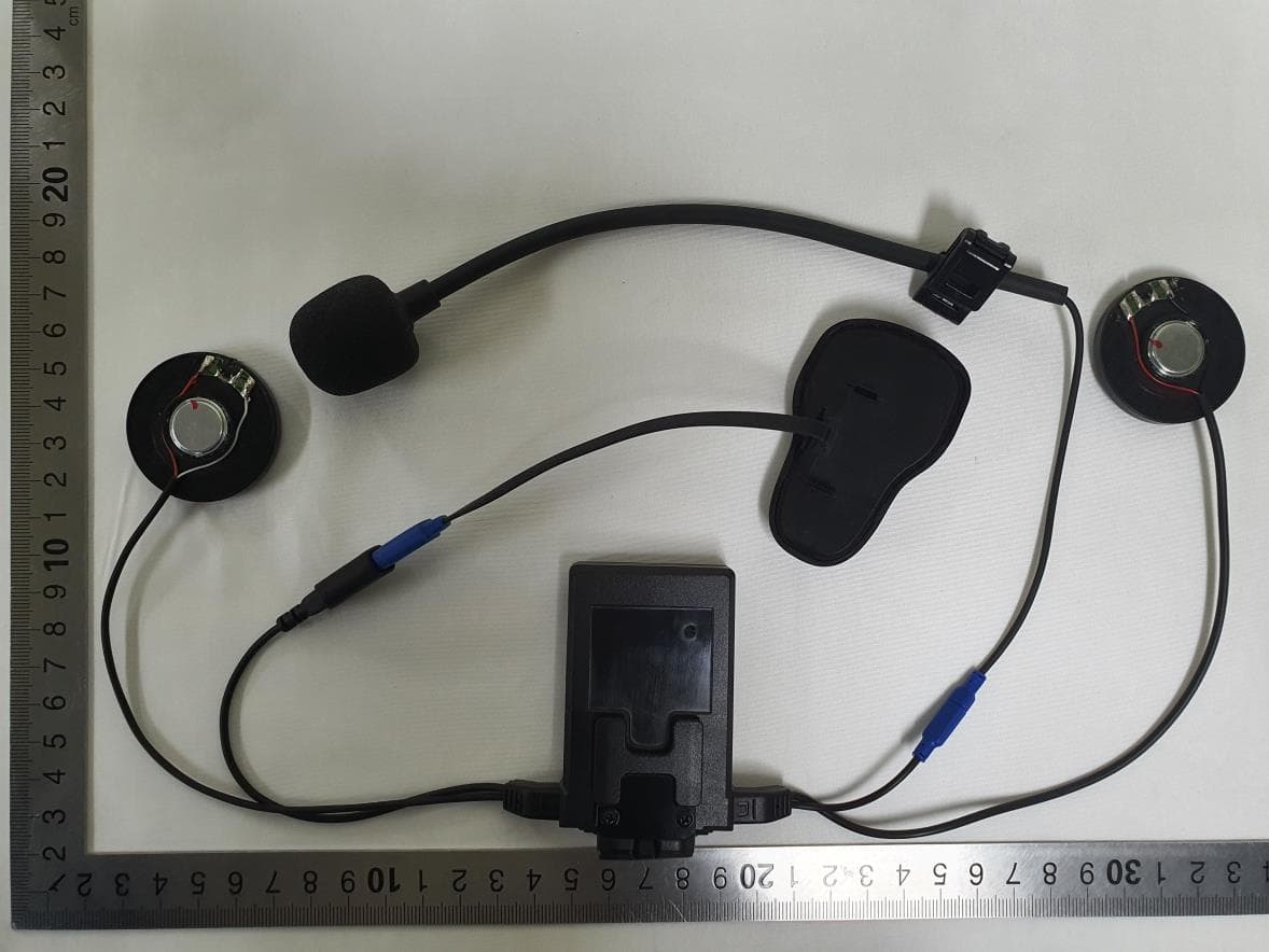
Y6MNCOM23
Nov 08, 2022N-Com B602 R
Equipment Class
DSS - Part 15 Spread Spectrum Transmitter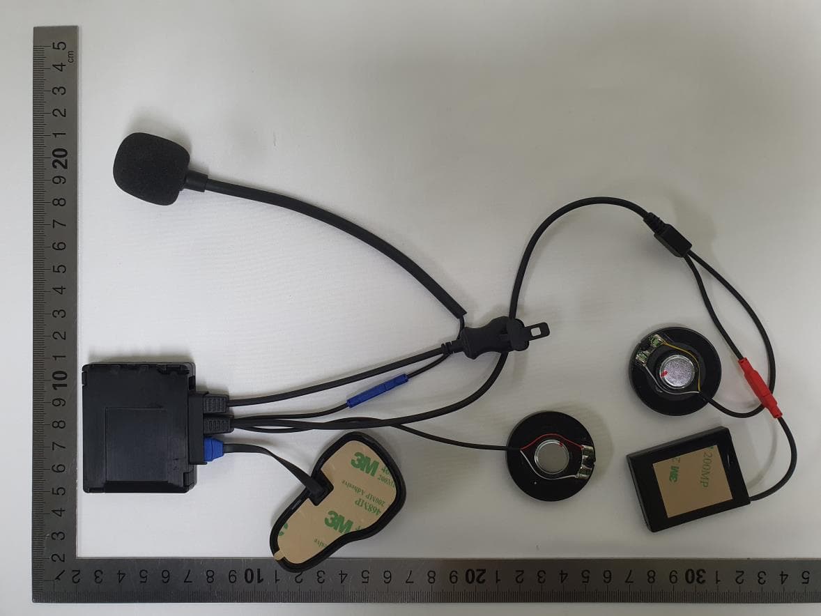
Y6MNCOM24
Nov 07, 2022N-Com B602 X
Equipment Class
DTS - Digital Transmission System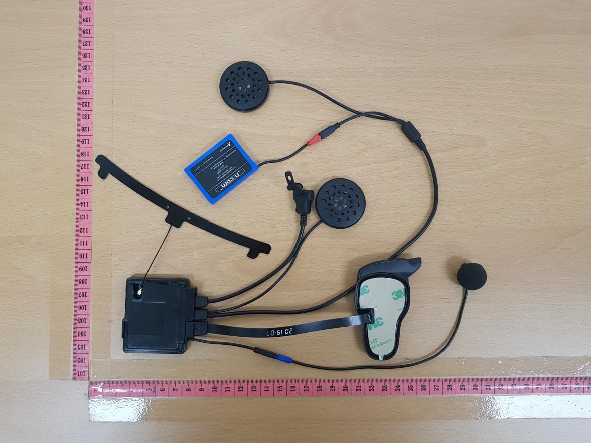
Y6MNCOM22
Oct 14, 2020N-Com B902 X
Equipment Class
DSS - Part 15 Spread Spectrum Transmitter