FCCID.CO- FCC ID Database
HomeCompaniesEquipment ClassesSearch

© 2026 FCC ID Database. All rights reserved.

AboutContactData sourced from FCC public records
  1. Home/
  2. Arnold & Richter Cine Technik GmbH & Co. Betriebs KG/
  3. Y7N-EMIP100

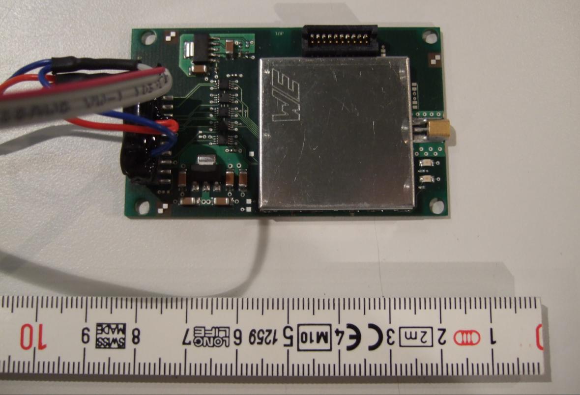
Y7N-EMIP100Wireless Remote Control for Lens and Cameracontrol
Arnold & Richter Cine Technik GmbH & Co. Betriebs KG
Wireless Remote Control for Lens and Cameracontrol - FCC ID Y7N-EMIP100 - Arnold & Richter Cine Technik GmbH & Co. Betriebs KG
Click to zoom

Application Details

Equipment Class
DTS - Digital Transmission System
Date of Grant
Mar 20, 2011
Application Purpose
Original Equipment
Date of Application
Mar 20, 2011
Equipment Note
Wireless Remote Control for Lens and Cameracontrol
Frequency Range
2405.00000000 - 2480.00000000
Company
Arnold & Richter Cine Technik GmbH & Co. Betriebs KG
Country
Germany

Documents & Files

Select a file to view
Users Manual

↗

Cover Letter(s)

↗
↗
↗

External Photos

↗

ID Label/Location Info

↗

Internal Photos

↗

Test Report

↗
↗

Test Setup Photos

↗

Document Text

Text extracted from the exhibit documents filed with the FCC. Open a document above to read the original.

Users Manual

Implementor’s Manual ARRI Document Number Ident Number Name Date Page WRS A-A 21.02.11 1 of 6 ARNOLD & RICHTER Tuerkenstrasse 89, 80799 Munich http://www.arri.de Information for “White” Radio Upgrade 1. Introduction/Description This document gives information regarding upgrade und labelling of ARRI Wireless Remote System units (WRS) with radio transceiver module FCC ID: Y7N-EMIP100 / IC: 9482A-EMIP100. 2. Devices Affected ARRICAM LDB ST/LT ARRI 416 Plus ARRI 435 Extreme/URM-3 ARRI Alexa Plus WCU-3 WMU-3 UMC-3 WZE-3 WMU-1/2 is not supported 3. Material and Parts list/Tools This will be stated in appropriate upgrade kit descriptions. 4. Service Information Status: o mandatory (material and labour free of charge) o recommended (material free of charge, labour to be paid by customer) x optional (material and labour to be paid by customer) 5. Detailed Description PRECAUTION: This Implementor’s Manual requires special skills and knowledge of the WRS Units. Please read this instruction carefully and start working only if you feel safe about completing it. If not, please contact ARRI Austria Service: Phone: +43/1/8920107-65 Fax: +43/1/8920107-12 ATTENTION Static sensitive components inside Radio Units Implementor’s Manual ARRI Document Number Ident Number Name Date Page WRS A-A 21.02.11 2 of 6 ARNOLD & RICHTER Tuerkenstrasse 89, 80799 Munich http://www.arri.de 6. Radio EMIP 1.00 (EMIP100) 16 dedicated channels: 1 2.405 GHz : 16 2.480 GHz Radio with FCC/IC Label Implementor’s Manual ARRI Document Number Ident Number Name Date Page WRS A-A 21.02.11 3 of 6 ARNOLD & RICHTER Tuerkenstrasse 89, 80799 Munich http://www.arri.de 7. Exterior Label Position on WCU-3 Unit Exterior Label Position on WCU-3 8. Exterior Label Position on UMC-3(A) Unit Exterior Label Position on UMC-3, UMC-3A Implementor’s Manual ARRI Document Number Ident Number Name Date Page WRS A-A 21.02.11 4 of 6 ARNOLD & RICHTER Tuerkenstrasse 89, 80799 Munich http://www.arri.de 9. Exterior Label Position on ALEXA Plus Unit Implementor’s Manual ARRI Document Number Ident Number Name Date Page WRS A-A 21.02.11 5 of 6 ARNOLD & RICHTER Tuerkenstrasse 89, 80799 Munich http://www.arri.de 10. Radio Label Dimensions and Specifications Material: Polyester, self adhesive, 19mm x 19mm 11. Exterior Label Dimensions and Specifications Material: Foil, FTC-ultra, self adhesive, 30mm x 10mm ARRI Transceiver Model: EMIP 100 5V 250mA FCC ID: Y7N-EMIP100 IC: 9482A-EMIP100 Implementor’s Manual ARRI Document Number Ident Number Name Date Page WRS A-A 21.02.11 6 of 6 ARNOLD & RICHTER Tuerkenstrasse 89, 80799 Munich http://www.arri.de 12. FCC and IC statements The following phrases need to be included in the final users manual of the end product: Canadian Compliance Statement Complies with the Canadian ICES-003 Class A specifications. Cet appareil numérique de la Classe A est conforme à la norme NMB-003 du Canada. This device complies with RSS 210 of Industry Canada. This Class A device meets all the requirements of the Canadian interference-causing equipment regulations. Cet appareil numérique de la Classe A respecte toutes les exigences du Réglement sur le matériel brouilleur du Canada. FCC Compliance Statement Section 15.19 This device complies with part 15 of the FCC Rules. Operation is subject to the following two conditions: (1) This device may not cause harmful interference, and (2) this device must accept any interference received, including interference that may cause undesired operation. Section 15.21 Information to user Changes or modifications not expressly approved by the party responsible for compliance could void the user's authority to operate the equipment Note: This device complies with part 15 of the FCC Rules. Operation is subject to the condition that this device does not cause harmful interference. Section 15.105(a) Note: This equipment has been tested and found to comply with the limits for a Class A digital device, pursuant to part 15 of the FCC Rules. These limits are designed to provide reasonable protection against harmful interference when the equipment is operated in a commercial environment. This equipment generates, uses, and can radiate radio frequency energy and, if not installed and used in accordance with the instruction manual, may cause harmful interference to radio communications. Operation of this equipment in a residential area is likely to cause harmful interference in which case the user will be required to correct the interference at his own expense. For any technical questions please call ARRI Austria +43 1 892 01 07-65 or send an e-mail to [email protected]

Cover Letter(s)

EMV Briefbogen 2008 ult 30.07.2008 10:39 Uhr Seite 1 Probedruck CMYCMMYCYCMYK Ersteller: U. Rodemeier Revision: 04 Erstelldatum: 03.08.01 Datum: 11.05.07 Seite 1 von 1 Request for Confidentiality PHOENIX TESTLAB GmbH Date: 2011-01-26 Product Certification Königswinkel 10 D 32825 Blomberg RE: Certification Application FCC ID: Y7N-EMIP100 Confidentiality Request Pursuant to Sections 0.457 and 0.459 of the Commission’s Rule, the applicant hereby requests confidential treatment of information accompanying this application as outlined below:  Block diagram  Schematics diagram  Functional description The above materials contain trade secrets and proprietary information not customarily released to the public. The public disclosure of these matters might be harmful to the applicant and provide unjustified benefits to its competitors. The applicant understands that pursuant to rule 0.457, disclosure of this application and all accompanying documentation will not be made before the date of the GRANT for this application. Thank you for your attention in this matter. Applicant’s Company address : Türkenstr. 89, 80799 Munich Signature : p.p. Job Title and Dept. : p.p. Marco Janker. EMV TESTHAUS GmbH

Cover Letter(s)

PART 15 UNLICENSED MODULAR TRANSMITTER APPROVAL For Wireless remote control EMIP100, 100409-AU01 1. The modular transmitter must have its own RF shielding. This is intended to ensure that the module does not have to rely upon the shielding provided by the device into which it is installed in order for all modular transmitter emissions to comply with Part 15 limits. It is also intended to prevent coupling between the RF circuitry of the module and any wires or circuits in the device into which the module is installed. Such coupling may result in noncompliant operation. Answer: The transmitter has its own shielding. 2. The modular transmitter must have buffered modulation/data inputs (if such inputs are provided) to ensure that the module will comply with Part 15 requirements under conditions of excessive data rates or over-modulation. Answer: Buffered data inputs are integrated in IC Freescale MC1322x PIP 3. The modular transmitter must have its own power supply regulation. This is intended to ensure that the module will comply with Part 15 requirements regardless of the design of the power supplying circuitry in the device into which the module is installed. Answer: The transmitter module is host powered but has its own power supply regulation. 4. The modular transmitter must comply with the antenna requirements of Section 15.203 and 15.204(c). The antenna must either be permanently attached or employ a “unique” antenna coupler (at all connections between the module and the antenna, including the cable). Any antenna used with the module must be approved with the module, either at the time of initial authorization or through a Class II permissive change. The “professional installation” provision of Section 15.203 may not be applied to modules. Answer: The modular approved transmitter is equipped with an external antenna connector of MMCX-type. This connector is not commonly available to end users. 5. The modular transmitter must be tested in a stand-alone configuration, i.e., the module must not be inside another device during testing. This is intended to demonstrate that the module is capable of complying with Part 15 emission limits regardless of the device into which it is eventually installed. Unless the transmitter module will be battery powered, it must comply with the AC line conducted requirements found in Section 15.207. AC or DC power lines and data input/output lines connected to the module must not contain ferrites, unless they will be marketed with the module (see Section 15.27(a)). The length of these lines shall be length typical of actual use or, if that length is unknown, at least 10 centimeters to insure that there is no coupling between the case of the module and supporting equipment. Any accessories, peripherals, or support equipment connected to the module during testing shall be unmodified or commercially available (see Section 15.31(i)). Answer: The RF module is tested in stand-alone configuration as documented in the test report and on the test setup photos. 6. The modular transmitter must be labeled with its own FCC ID number, and, if the FCC ID is not visible when the module is installed inside another device, then the outside of the device into which the module is installed must also display a label referring to the enclosed module. This exterior label can use wording such as the following: “Contains Transmitter Module FCC ID: XYZMODEL1” or “Contains FCC ID: XYZMODEL1.” Any similar wording that expresses the same meaning may be used. The Grantee may either provide such a label, an example of which must be included in the application for equipment authorization, or, must provide adequate instructions along with the module which explain this requirement. In the latter case, a copy of these instructions must be included in the application for equipment authorization. Answer: The modular approved transmitter is labeled with it’s own FCC ID. The final host product, into which this modular approved transmitter is finally integrated, will be labelled with an auxiliary label, such as: 7. The modular transmitter must comply with any specific rule or operating requirements applicable to the transmitter and the manufacturer must provide adequate instructions along with the module to explain any such requirements. A copy of these instructions must be included in the application for equipment authorization. For example, there are very strict operational and timing requirements that must be met before a transmitter is authorized for operation under Section 15.231. For instance, data transmission is prohibited, except for operation under Section 15.231(e), in which case there are separate field strength level and timing requirements. Compliance with these requirements must be assured. Answer: No requirements for devices subject to Section 15.247 6. The modular transmitter must be labeled with its own FCC ID number, and, if the FCC ID is not visible when the module is installed inside another device, then the outside of the device into which the module is installed must also display a label referring to the enclosed module. This exterior label can use wording such as the following: “Contains Transmitter Module FCC ID: XYZMODEL1” or “Contains FCC ID: XYZMODEL1.” Any similar wording that expresses the same meaning may be used. The Grantee may either provide such a label, an example of which must be included in the application for equipment authorization, or, must provide adequate instructions along with the module which explain this requirement. In the latter case, a copy of these instructions must be included in the application for equipment authorization. Answer: The modular approved transmitter is labeled with it’s own FCC ID. The final host product, into which this modular approved transmitter is finally integrated, will be labelled with an auxiliary label, such as: 7. The modular transmitter must comply with any specific rule or operating requirements applicable to the trans…

Text truncated - open the document above for the full version.

External Photos

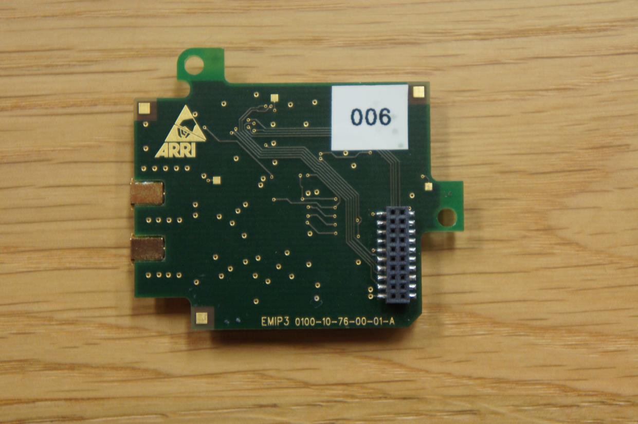
EMV TESTHAUS GmbH Gustav-Hertz-Straße 35 94315 Straubing Germany Revision: 1.01 Arnold & Richter Cine Technik GmbH & Co. Betriebs KG Funkmodul 100409-AU01+E02 Annex B Page 1 of 3 1 Annex B – EUT pictures 1.1 List of Pictures Picture 1: EUT front side.................................................................................................... 2 Picture 2: EUT back side ................................................................................................... 2 Picture 4: EUT antenna connector ..................................................................................... 3 Picture 5: EUT (shielding removed) ................................................................................... 3 EMV TESTHAUS GmbH Gustav-Hertz-Straße 35 94315 Straubing Germany Revision: 1.01 Arnold & Richter Cine Technik GmbH & Co. Betriebs KG Funkmodul 100409-AU01+E02 Annex B Page 2 of 3 Picture 1: EUT front side Picture 2: EUT back side EMV TESTHAUS GmbH Gustav-Hertz-Straße 35 94315 Straubing Germany Revision: 1.01 Arnold & Richter Cine Technik GmbH & Co. Betriebs KG Funkmodul 100409-AU01+E02 Annex B Page 3 of 3 Picture 3: EUT antenna connector Picture 4: EUT (shielding removed)

ID Label/Location Info

AR R I Tra nsce ive r Model: EMIP 100 5V 250mA FCC ID: Y7N-EMIP100 IC: 9482A-EMIP100 Lable Location Info Lable

Internal Photos

EMV TESTHAUS GmbH Gustav-Hertz-Straße 35 94315 Straubing Germany Revision: 1.01 Arnold & Richter Cine Technik GmbH & Co. Betriebs KG Funkmodul 100409-AU01+E02 Annex B Page 1 of 3 1 Annex B – EUT pictures 1.1 List of Pictures Picture 1: EUT front side.................................................................................................... 2 Picture 2: EUT back side ................................................................................................... 2 Picture 4: EUT antenna connector ..................................................................................... 3 Picture 5: EUT (shielding removed) ................................................................................... 3 EMV TESTHAUS GmbH Gustav-Hertz-Straße 35 94315 Straubing Germany Revision: 1.01 Arnold & Richter Cine Technik GmbH & Co. Betriebs KG Funkmodul 100409-AU01+E02 Annex B Page 2 of 3 Picture 1: EUT front side Picture 2: EUT back side EMV TESTHAUS GmbH Gustav-Hertz-Straße 35 94315 Straubing Germany Revision: 1.01 Arnold & Richter Cine Technik GmbH & Co. Betriebs KG Funkmodul 100409-AU01+E02 Annex B Page 3 of 3 Picture 3: EUT antenna connector Picture 4: EUT (shielding removed)

Test Report

The test result refers exclusively to the model tested. This report must not be copied without the written authorization by the lab. Revision: 1.0 DGA-PL-224/95-03 / BNetzA-CAB-02/21-02/2 Customer: Arnold & Richter Cine Technik GmbH & Co. Betriebs KG Türkenstr. 89 D-80799 Munich Tel.: +49 89 3809-1205 Fax: +49 89 3809-111205 RF test report 100409-AU01+E02 Arnold & Richter Cine Technik GmbH & Co. Betriebs KG RF module EMIP100 EMV TESTHAUS GmbH Gustav-Hertz-Straße 35 94315 Straubing Germany Revision: 1.0 Arnold & Richter Cine Technik GmbH & Co. Betriebs KG RF module EMIP100 100409-AU01+E02 Page 2 of 59 EMV TESTHAUS GmbH Gustav-Hertz-Straße 35 94315 Straubing Tel.: +49 9421 56868-0 Fax: +49 9421 56868-100 Email: [email protected] Accreditation: Registration number: DGA-PL-224/95-03 CAB (EMC) registration number: BNetzA-CAB-02/21-02/3 FCC facility registration number: 221458 MRA US-EU, FCC designation number: DE0010 Location of Testing: EMV TESTHAUS GmbH Gustav-Hertz-Straße 35 94315 Straubing Germany The technical accuracy is guaranteed through the quality management of the EMV TESTHAUS GmbH EMV TESTHAUS GmbH Gustav-Hertz-Straße 35 94315 Straubing Germany Revision: 1.0 Arnold & Richter Cine Technik GmbH & Co. Betriebs KG RF module EMIP100 100409-AU01+E02 Page 3 of 59 Table of contents 1 Test regulations ........................................................................................................................ 6 2 Equipment under Test (EUT) .................................................................................................... 7 3 AC power line conducted emissions ....................................................................................... 10 4 Duty cycle / Averaging factor .................................................................................................. 16 5 Maximum conducted output power ......................................................................................... 18 6 Power spectral density measurement ..................................................................................... 22 7 6dB spectrum bandwidth measurement .................................................................................. 26 8 Radiated emission measurement (<1 GHz) ............................................................................ 30 9 Radiated emission measurement (>1 GHz) ............................................................................ 43 10 Exposure of humans to RF fields ............................................................................................ 56 11 Equipment calibration status ................................................................................................... 57 12 Measurement uncertainty ....................................................................................................... 58 13 Summary ................................................................................................................................ 59 EMV TESTHAUS GmbH Gustav-Hertz-Straße 35 94315 Straubing Germany Revision: 1.0 Arnold & Richter Cine Technik GmbH & Co. Betriebs KG RF module EMIP100 100409-AU01+E02 Page 4 of 59 List of pictures Picture 1: Outline of conducted emission test setup ................................................................. 11 Picture 2: Conducted emission on mains, phase 1 (Chart) ....................................................... 12 Picture 3: Conducted emission on mains, phase 1 (Table) ....................................................... 13 Picture 4: Conducted emission on mains, neutral (Chart) ......................................................... 14 Picture 5: Conducted emission on mains, neutral (Table) ......................................................... 15 Picture 6: Duty cycle (T on ) ......................................................................................................... 16 Picture 7: Duty cycle ................................................................................................................. 17 Picture 8: Test setup for conducted output power measurement .............................................. 19 Picture 9: Conducted output power channel 11 ........................................................................ 20 Picture 10: Conducted output power channel 18 ...................................................................... 20 Picture 11: Conducted output power channel 26 ...................................................................... 21 Picture 12: Test setup for power spectral density measurement ............................................... 23 Picture 13: Power spectral density channel 11 ......................................................................... 24 Picture 14: Power spectral density channel 18 ......................................................................... 24 Picture 15: Power spectral density channel 26 ......................................................................... 25 Picture 16: Test setup for 6dB spectrum bandwidth measurement ........................................... 27 Picture 17: 6dB spectrum bandwidth channel 11 ...................................................................... 28 Picture 18: 6dB spectrum bandwidth channel 18 ...................................................................... 28 Picture 19: 6dB spectrum bandwidth channel 26 ...................................................................... 29 Picture 20: Test setup for radiated emission measurement (< 30 MHz) .................................... 31 Picture 21: Test setup for radiated emission measurement (< 1 GHz) ...................................... 32 Picture 22: Radiated emission 9 kHz – 30 MHz ........................................................................ 33 Picture 23: Radiated emission 30 MHz – 1000MHz (Channel 11) ............................................ 34 Picture 24: Radiated emission 30 MHz – 1000MHz (Table, channel 11) .…

Text truncated - open the document above for the full version.

Test Report

EMV TESTHAUS GmbH Gustav-Hertz-Straße 35 94315 Straubing Germany Revision: 1.01 Arnold & Richter Cine Technik GmbH & Co. Betriebs KG RF module EMIP100 100409-AU01+E02 Annex C Page 1 of 3 1 Annex C – documentation 1.1 List of Pictures Picture 1: Antenna specification (S131AH-2450S) ............................................................ 2 Picture 2: Antenna specification (MMSO2300) .................................................................. 3 EMV TESTHAUS GmbH Gustav-Hertz-Straße 35 94315 Straubing Germany Revision: 1.01 Arnold & Richter Cine Technik GmbH & Co. Betriebs KG RF module EMIP100 100409-AU01+E02 Annex C Page 2 of 3 Picture 1: Antenna specification (S131AH-2450S) EMV TESTHAUS GmbH Gustav-Hertz-Straße 35 94315 Straubing Germany Revision: 1.01 Arnold & Richter Cine Technik GmbH & Co. Betriebs KG RF module EMIP100 100409-AU01+E02 Annex C Page 3 of 3 Picture 2: Antenna specification (MMSO2300)

Test Setup Photos

EMV TESTHAUS GmbH Gustav-Hertz-Straße 35 94315 Straubing Germany Revision: 1.01 Arnold & Richter Cine Technik GmbH & Co. Betriebs KG Funkmodul 100409-AU01+E02 Annex A Page 1 of 5 1 Annex A – Test setup 1.1 List of Pictures Picture 1: Test setup radiated emission (front view) .......................................................... 2 Picture 2: Test setup radiated emission (rear view) ........................................................... 2 Picture 3: Test setup conducted emission (front view) ...................................................... 3 Picture 4: Test setup conducted emission (rear view) ....................................................... 4 Picture 5: Test setup conducted measurement ................................................................. 5 EMV TESTHAUS GmbH Gustav-Hertz-Straße 35 94315 Straubing Germany Revision: 1.01 Arnold & Richter Cine Technik GmbH & Co. Betriebs KG Funkmodul 100409-AU01+E02 Annex A Page 2 of 5 Picture 1: Test setup radiated emission (front view) Picture 2: Test setup radiated emission (rear view) EMV TESTHAUS GmbH Gustav-Hertz-Straße 35 94315 Straubing Germany Revision: 1.01 Arnold & Richter Cine Technik GmbH & Co. Betriebs KG Funkmodul 100409-AU01+E02 Annex A Page 3 of 5 Picture 3: Test setup conducted emission (front view) EMV TESTHAUS GmbH Gustav-Hertz-Straße 35 94315 Straubing Germany Revision: 1.01 Arnold & Richter Cine Technik GmbH & Co. Betriebs KG Funkmodul 100409-AU01+E02 Annex A Page 4 of 5 Picture 4: Test setup conducted emission (rear view) EMV TESTHAUS GmbH Gustav-Hertz-Straße 35 94315 Straubing Germany Revision: 1.01 Arnold & Richter Cine Technik GmbH & Co. Betriebs KG Funkmodul 100409-AU01+E02 Annex A Page 5 of 5 Picture 5: Test setup conducted measurement

Contact Information

Applicant

Juergen Althammer(QMR)
[email protected]0049-89-3809Fax: 0049-89-3809-111205

Test Firm

EMV Testhaus GmbHMr. Rainer Heller
[email protected]49-9421-56868-0Fax: 49-9421-56868-100

Technical Specifications

#Rule PartsFrequency RangePower Output
115C2.40 GHz - 2.48 GHz2.00 mW
Modular Type
Single Modular Approval
Confidentiality
Long Term
Grant Notes
Output power listed is conducted. This OEM module is approved for use in products operating as portable transmitting device. The only antennas approved for use with this module are those documented in the filing, and must be installed in the manner specified therein. End users may not be provided with the module installation instructions.

Other Applications from Arnold & Richter Cine Technik GmbH & Co. Betriebs KG

Radio Module - FCC ID Y7N-EMIP300 - Arnold & Richter Cine Technik GmbH & Co. Betriebs KG
Y7N-EMIP300

Radio Module

May 12, 2015

Equipment Class

DTS - Digital Transmission System