FCCID.CO- FCC ID Database
HomeCompaniesEquipment ClassesSearch

© 2026 FCC ID Database. All rights reserved.

AboutContactData sourced from FCC public records
  1. Home/
  2. Cooper Power Systems/
  3. Y86-50760X31

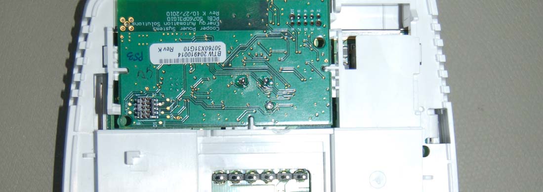
Y86-50760X31Zigbee communication board for Honeywell UtilityPRO thermostat

Cooper Power Systems
Zigbee communication board for Honeywell UtilityPRO thermostat - FCC ID Y86-50760X31 - Cooper Power Systems
Click to zoom

Application Details

Equipment Class
DTS - Digital Transmission System
Date of Grant
Apr 27, 2011
Application Purpose
Original Equipment
Date of Application
Apr 27, 2011
Equipment Note
Zigbee communication board for Honeywell UtilityPRO thermostat
Frequency Range
2400.00000000 - 2483.50000000
Company
Cooper Power Systems
Country
United States

Documents & Files

Select a file to view

Users Manual

↗

Cover Letter(s)

↗

External Photos

↗

ID Label/Location Info

↗

Internal Photos

↗

Test Report

↗

Test Setup Photos

↗

Document Text

Text extracted from the exhibit documents filed with the FCC. Open a document above to read the original.

Users Manual

Fri SAVINGS Operating Manual UtilityPRO TM Series Touchscreen Programmable Demand Control Thermostat 85-3126-2 Read and save these instructions. Need Help? For assistance or warranty information please call your local Utility at the number found on the front of the thermostat. ® U.S. Registered Trademark. US Patents pending. Copyright © 2009 Honeywell International Inc. All rights reserved. BE CAREFUL! Never use sharp instruments, such as a pencil or pen, to press touchscreen keys. To prevent damage to the thermostat, always press keys with your fingertip. This thermostat contains a Lithium battery which may contain Perchlorate material.Perchlorate Material—special handling may apply, See www.dtsc.ca.gov/hazardouswaste/perchlorate Battery Replacement The UtilityPRO is shipped from the factory with the coin cell installed. To keep the battery from discharging during shipment and storage, the UtilityPRO is shipped from the factory with a plastic tab inserted in the battery holder. This tab must be removed before the thermostat is mounted on the wall. Simply pull the plastic tab out of the thermostat. To replace the battery, remove the battery tray using a screw driver. Place a new coin cell (type CR2032 or equivalent) observing the correct polarity and push the battery tray into the battery cover assembly. The UtilityPRO has a coin cell battery that retains the time and date during a power failure. Under normal circumstances the coin cell should last five years. Should the time and date need to be reset after a power failure, this is an indication that the coin cell needs to be replaced. You should replace the battery every five years, or before leaving home for an extended period. Coin cell battery tray Battery Cover Assembly Insert the coin cell battery in the coin cell battery tray and push it inside the battery cover assembly This equipment has been tested and found to comply with the limits for a Class B digital device, pursuant to part 15 of the FCC Rules. Operation is subject to the following two conditions:1) This device may not cause harmful interference. 2) This device must accept any interference received, including interference that may cause undesired operation.Class B limits are designed to provide reasonable protection against harmful interference in a residential installation. This equipment generates, uses, and can radiate radio frequency energy, and, if not installed and used in accordance with the instructions, may cause harmful interference to radio communications. However, there is no guarantee that interference will not occur in a particular installation. If this equipment does cause harmful interference to radio or television reception, which c an be determined by turning the equipment off and on, the user is encouraged to try to correct the interference by one or more of the following measures: • Reorient the receiving antenna.• Increase the distance between the equipment and the receiver.• Connect the equipment into an outlet on a circuit different from that to which the receiver is connected.• Consult the installer or an experienced radio/TV technician for help. Industry Canada Requirements Operation of this device is subject to the following two conditions: 1) This device may not cause interference.2) This device must accept any interference, including interference that may cause undesired operation of the device. FCC Part 15 Notice 1 About your new thermostat Thermostat Features .................................. 2 Getting Started Quick Reference to Controls ..................... 3Quick Reference to Status Display ........... 4 Subscription Services Demand Control ......................................... 5Utility Usages ............................................. 6Utility Messages ......................................... 6View Message ............................................ 7Usage & Billing ........................................... 8 Settings Fan Settings ............................................... 9System Settings ....................................... 10Schedule Settings .................................... 11Program Schedule Override (Temp) ........ 12Schedule Override (Permanent) .............. 13Clock Settings .......................................... 14 Programming & Operation Program Schedules ............................15-16 Special Features ...................................... 17Screen Lock ............................................. 18Screen Cleaning ....................................... 19Advanced Functions ...........................20-23Troubleshooting ..................................24-25 This thermostat is ready to go! Your new thermostat is pre-programmed and ready to go. See page 15 to check settings. Table of contents CAUTION: EQUIPMENT DAMAGE HAZARD. To pr event pos sible compressor damage, do not operate cooling system when outdoor temperature is below 50 ̊ F (10 ̊ C). UtilityPRO TM Series Operating Manual 2 UtilityPro TM Features Congratulations! You’ve just purchased the world’s most advanced, easy-to-use thermostat. It has been designed to give you many years of reliable service and touchscreen climate control.Features • Provides Utility information messages.• Provides Utility billing information.• 5/1/1 and 5/2-day program schedules maximize comfort and economy.• Demand response thermostat programmed to aid you in your savings.• One-touch temp control overrides program schedule at any time.• Precise comfort control keeps temperature within 1°F of the level you set.• Provides demand control messages.• Large touchscreen display with backlight is easy to read—even in the dark. UtilityPRO TM Series 3 SUN TIER MEDIUM Press day(s) to set program schedule (see page 11) Displays the current tier ratePress to select fan operation Press to select system type Press to set program schedule Press to view messages Press to adjust temperature settingsPress to view the subscribed service messages Press to override program schedu…

Text truncated - open the document above for the full version.

Test Report

TEST REPORT Report Number: 100339494MIN-001 Project Number: G10033949 Testing performed on the 50760X31 FCC ID: Y86-50760X31 Industry Canada ID: 6766C-50760X31 to 47 CFR Part 15. 247:2009 RSS- 210, Issue 8, 2010 RSS-Gen, Issue 3, 2010 47 CFR, Part 15:2009, §15.107 and §15.109, Class B ICES-003, Issue 4:2004 For Cooper Power Systems Cannon Technologies Test Performed by: Test Authorized by: Intertek Testing Services NA, Inc. 7250 Hudson Blvd., Suite 100 Oakdale, MN 55128 USA Cooper Power Systems Cannon Technologies 505 Hwy 169 North Minneapolis, MN 55427, USA Prepared by: Date: March 30, 2011 Richard Blonigen Reviewed by: Date: March 30, 2011 Norman Shpilsher This report is for the exclusive use of Intertek's Client and is provided pursuant to the agreement between Intertek and its Client. Intertek's responsibility and liability are limited to the terms and conditions of the agreement. Intertek assumes no liability to any party, other than to the Client in accordance with the agreement, for any loss, expense or damage occasioned by the use of this report. Only the Client is authorized to copy or distribute this report and then only in its entirety. Any use of the Intertek name or one of its marks for the sale or advertisement of the tested material, product or service must first be approved in writing by Intertek. The observations and test results in this report are relevant only to the sample tested. This report by itself does not imply that the material, product, or service is or has ever been under an Intertek certification program. This report must not be used to claim product endorsement by A2LA, NIST nor any other agency of the U.S. Government. EMC Report No: 100339494MIN-001 FCC ID: Y86-50760X31 IC ID:6766C-50760X31 Page 2 of 48 TABLE OF CONTENTS 1.0 GENERAL DESCRIPTION................................ ................................................................ ................................................................ ................................................................ .............................................. ............................ .............. 3 33 3 1.1 Product Description; Test Facility ....................................................................................... 4 1.3 Environmental conditions.................................................................................................... 5 1.4 Measurement uncertainty ................................................................................................... 6 1.5 Field Strength Calculation................................................................................................... 6 2.0 TEST SUMMARY................................ ................................................................ ................................................................ ................................................................ .......................................................... .................................................... .......................... 7 77 7 3.0 TEST CONDITIONS AND RESULTS................................ ................................................................ ................................................................ ................................................................ ................................. .. . 8 88 8 3.1 Maximum peak output power.............................................................................................. 8 3.2 6dB bandwidth of the digital modulation........................................................................... 12 3.3 Power spectral density ...................................................................................................... 16 3.4 Antenna conducted spurious emissions ........................................................................... 20 3.5 Radiated spurious emissions............................................................................................ 32 3.6 RF Exposure Compliance ................................................................................................. 37 3.7 Transmitter power line conducted emissions ................................................................... 38 3.8 Receiver/digital device radiated emissions....................................................................... 41 3.9 Digital device conducted emissions.................................................................................. 45 4.0 TEST EQUIPMENT................................ ................................................................ ................................................................ ................................................................ ....................................................... .............................................. .......................48 4848 48 EMC Report No: 100339494MIN-001 FCC ID: Y86-50760X31 IC ID:6766C-50760X31 Page 3 of 48 1.0 GENERAL DESCRIPTION Model: 50760X31 Type of EUT: Thermostat Communication Module FCC ID: Y86-50760X31 Industry Canada ID: 6766C-50760X31 Related Submittal(s) Grants: None Company: Cooper Power Systems Cannon Technologies Customer: Mr. Nathan Brandt Address: 505 Hwy 169 North Minneapolis, MN 55427, USA Phone: (763) 543-7770 Fax: (763) 595-7776 e-mail: [email protected] Test Standards: 47 CFR, Part 15:2009, §15.247 RSS–210, Issue 8, 20010 RSS-Gen, Issue 3, 2010 47 CFR, Part 15:2009, §15.107 and §15.109, Class B ICES-003, Issue 4:2004 Other Type of radio: Stand -alone Module Hybrid Date Sample Submitted: February 23, 2011 Test Work Started: February 23, 2011 Test Work Completed: February 28, 2011 Test Sample Conditions: Damaged Poor (Usable) Good EMC Report No: 100339494MIN-001 FCC ID: Y86-50760X31 IC ID:6766C-50760X31 Page 4 of 48 1.1 Product Description; Test Facility Product Description: 2.4 – 2.4835GHz Transceiver Transmitter Type: FHSS Digital Modulation WiFi Blue Tooth Operating Frequency Range(s): 2400-2483.5MHz Number of…

Text truncated - open the document above for the full version.

Test Setup Photos

Test Setup Photos

Contact Information

Applicant

Nathan Allen Brandt(Design Engineer)
[email protected]763-543-7770Fax: 763-543-7777

Test Firm

Intertek Testing ServicesUri Spector
[email protected]651-730-1188Fax: 651-730-1282

Technical Specifications

#Rule PartsFrequency RangePower Output
115C2.40 GHz - 2.48 GHz25.00 mW
Confidentiality
Long Term

Other Applications from Cooper Power Systems

Y86-62020X31

ZigBee Radio Installed in Load Controlled Receiver

Dec 12, 2011

Equipment Class

DTS - Digital Transmission System