FCCID.CO- FCC ID Database
HomeCompaniesEquipment ClassesSearch

© 2026 FCC ID Database. All rights reserved.

AboutContactData sourced from FCC public records
  1. Home/
  2. Cooper Power Systems/
  3. Y86-62020X31

Y86-62020X31ZigBee Radio Installed in Load Controlled Receiver

Cooper Power Systems

Application Details

Equipment Class
DTS - Digital Transmission System
Date of Grant
Dec 12, 2011
Application Purpose
Original Equipment
Date of Application
Dec 12, 2011
Equipment Note
ZigBee Radio Installed in Load Controlled Receiver
Frequency Range
2405.00000000 - 2480.00000000
Company
Cooper Power Systems
Country
United States

Documents & Files

Select a file to view

Users Manual

↗

Cover Letter(s)

↗

External Photos

ID Label/Location Info

Internal Photos

Test Report

↗

Test Setup Photos

↗

Document Text

Text extracted from the exhibit documents filed with the FCC. Open a document above to read the original.

Users Manual

Instructional Leaflet Customer Service: 1-800-815-2258 This instructional leaflet contains general installation information for the LCR 6200 Load Control Receiver. The LCR 6200 is used to control remote electric loads and is activated by commands sent through the SelectComm™ and ZigBee communication modules. No special test equipment or programming is required to install the LCR 6200 in the field. The LCR 6200 addressing must be configured for your demand response system prior to operation. CAUTION:Observe precautions for handling electrostatic sensitive devices. MISE EN GARDE:Respectez les précautions de manipulation des dispositifs à décharge électrostatique. LCR 6200 Load Control Receiver SAFETY FOR LIFE Cooper Power Systems™ products meet or exceed all applicable industry standards relating to product safety. We actively promote safe practices in the use and maintenance of our products through our service literature, instructional training programs, and the continuous efforts of all Cooper Power Systems employees involved in product design, manufacture, marketing, and service. We strongly urge that you always follow all locally approved safety procedures and safety instructions when working around high voltage lines and equipment and support our “Safety For Life” mission. SAFETY INFORMATION The instructions in this document are not intended as a substitute for proper training or adequate experience in the safe operation of the equipment described. Only competent technicians, who are familiar with this equipment should install, operate, and service it. A competent technician has these qualifications: • Is thoroughly familiar with these instructions. • Is trained in industry-accepted high and low- voltage safe operating practices and procedures. • Is trained and authorized to energize, de-energize, clear, and ground power distribution equipment. • Is trained in the care and use of protective equipment such as flash clothing, safety glasses, face shield, hard hat, rubber gloves, hot stick, etc. Following is important safety information. For safe installation and operation of this equipment, be sure to read and understand all cautions and warnings. Safety Instructions Following are general danger and warning statements that apply to PLC equipment. Additional statements, related to specific tasks and procedures, are located throughout the document. ! SAFETY FOR LIFE ! SAFETY FOR LIFE Hazard Statement Definitions This document may contain four types of hazard statements: DANGER:Indicates a hazardous situation which, if not avoided, will result in death or serious injury. WARNING:Indicates a hazardous situation which, if not avoided, could result in death or serious injury. CAUTION:Indicates a hazardous situation which, if not avoided, could result in minor or moderate injury or equipment damage. CAUTION:Indicates a potentially hazardous situation which, if not avoided, may result in equipment damage only. DANGER:Hazardous voltage. Contact with hazardous voltage will cause death or severe personal injury. Follow all locally approved safety procedures when working around high and low-voltage lines and equipment. G103.3 DANGER:Before installing, operating, maintaining, or testing this equipment, carefully read and understand the contents of this document. Improper operation, handling, or maintenance can result in death, severe personal injury, and equipment damage. G101.0 DANGER:This equipment is not intended to protect human life. Follow all locally approved procedures and safety practices when installing or operating this equipment. Failure to comply may result in death, severe personal injury, and equipment damage. G102.1 DANGER:Power distribution and transmission equipment must be properly selected for the intended application. It must be installed and serviced by competent personnel who have been trained and understand proper safety procedures. These instructions are written for such personnel and are not a substitute for adequate training and experience in safety procedures. Failure to properly select, install, or maintain power distribution and transmission equipment can result in death, severe personal injury, and equipment damage. G102.1 Cooper Power Systems3 CT-Y0-0398 ! SAFETY FOR LIFE Installing the LCR 6200 Complete the following steps to install an LCR 6200: 1. Mount the LCR 6200 at the desired location, which is preferably a flat, non-vibrating surface. The LCR enclosure has two pre-drilled mounting tabs. Cooper Power Systems recommends pan head screws up to 1/4” in size for mounting the LCR. The distance between the mounting holes is 8.25 inches, and the diameter of the mounting holes is 0.3125 inches. For a rain-tight rating, mount the LCR so that the “This Way Up” arrow on the label points up. 2. Remove electrical power from the AC circuits that are to supply power to the LCR and the load to be controlled. 3. Wire the LCR 6200 according to the wiring diagram located on the LCR cover. Install the wiring within a 1/2” liquid-tight, non- metallic, flexible conduit or make sure the wiring is close nippled into an approved junction box or wiring compartment. All wiring connections are made to factory- installed leads that are rated for 600 VAC, 105° C. No polarity requirements apply to the output leads. 4. Locate and record the LCR address, Install Code, EUI-64 address, and any other necessary information. 5. Apply electrical power to the LCR. 6. Commission the ZigBee module by performing the steps described in “Commissioning the ZigBee Module” on page 4. 7. If desired, perform a test shed as described in the section “Test Button” on page 5. 8. Close the LCR door, secure the latch, and install a utility seal. WARNING:Dangerous voltages are present. Multiple disconnects may be required to de-energize all circuits. AVERTISSEMENT:Présence de tensions dangereuses. Il pourrait être nécessaire de procéder à des débranchements multiples pour mettre tous les circuits hors tension. 4Instr…

Text truncated - open the document above for the full version.

Test Report

TEST REPORT Report Number: 100525686MIN-001 Project Number: G100525686 Testing performed on the LCR 6200 FCC ID: Y86-62020X31 Industry Canada ID: 6766C-62020X31 to 47 CFR Part 15. 247:2010 RSS- 210, Issue 8, 2010 RSS-Gen, Issue 3, 2010 47 CFR, Part 15:2010, §15.107 and §15.109, Class B ICES-003, Issue 4:2004 For Cooper Power Systems Cannon Technologies Test Performed by: Test Authorized by: Intertek Testing Services NA, Inc. 7250 Hudson Blvd., Suite 100 Oakdale, MN 55128 USA Cooper Power Systems Cannon Technologies 505 Hwy 169 North Minneapolis, MN 55427, USA Prepared by: Date: October 26, 2011 Uri Spector Reviewed by: Date: October 26, 2011 Norman Shpilsher This report is for the exclusive use of Intertek's Client and is provided pursuant to the agreement between Intertek and its Client. Intertek's responsibility and liability are limited to the terms and conditions of the agreement. Intertek assumes no liability to any party, other than to the Client in accordance with the agreement, for any loss, expense or damage occasioned by the use of this report. Only the Client is authorized to copy or distribute this report and then only in its entirety. Any use of the Intertek name or one of its marks for the sale or advertisement of the tested material, product or service must first be approved in writing by Intertek. The observations and test results in this report are relevant only to the sample tested. This report by itself does not imply that the material, product, or service is or has ever been under an Intertek certification program. This report must not be used to claim product endorsement by A2LA, NIST nor any other agency of the U.S. Government. EMC Report No: 100525686MIN-001 FCC ID: Y86-62020X31 IC ID:6766C-62020X31 Page 2 of 61 TABLE OF CONTENTS 1.0 GENERAL DESCRIPTION.......................................................................................................... 3 1.1 Product Description; Test Facility ....................................................................................... 4 1.3 Environmental conditions.................................................................................................... 5 1.4 Measurement uncertainty ................................................................................................... 6 1.5 Field Strength Calculation................................................................................................... 6 2.0 TEST SUMMARY.......................................................................................................................... 7 3.0 TEST CONDITIONS AND RESULTS........................................................................................ 8 3.1 Maximum peak output power.............................................................................................. 8 3.2 6dB bandwidth of the digital modulation........................................................................... 12 3.3 Power spectral density ...................................................................................................... 16 3.4 Antenna conducted spurious emissions ........................................................................... 20 3.5 Radiated spurious emissions............................................................................................ 29 3.5.1 Average correction factor calculation ................................................................................... 32 3.6 RF Exposure Compliance ................................................................................................. 50 3.7 Transmitter power line conducted emissions ................................................................... 51 3.8 Receiver/digital device radiated emissions....................................................................... 54 3.9 Digital device conducted emissions.................................................................................. 58 4.0 TEST EQUIPMENT..................................................................................................................... 61 EMC Report No: 100525686MIN-001 FCC ID: Y86-62020X31 IC ID:6766C-62020X31 Page 3 of 61 1.0 GENERAL DESCRIPTION Model: 62020X31 Type of EUT: Load Control Switch FCC ID: Y86-62020X31 Industry Canada ID: 6766C-62020X31 Related Submittal(s) Grants: None Company: Cooper Power Systems Cannon Technologies Customer: Mr. Nathan Brandt Address: 505 Hwy 169 North Minneapolis, MN 55427, USA Phone: (763) 543-7770 Fax: (763) 595-7776 e-mail: [email protected] Test Standards: 47 CFR, Part 15:2010, §15.247 RSS–210, Issue 8, 2010 RSS-Gen, Issue 3, 2010 47 CFR, Part 15:2009, §15.107 and §15.109, Class B ICES-003, Issue 4:2004 Other Type of radio: Stand -alone Module Hybrid Date Sample Submitted: October 17, 2011 Test Work Started: October 17, 2011 Test Work Completed: October 26, 2011 Test Sample Conditions: Damaged Poor (Usable) Good EMC Report No: 100525686MIN-001 FCC ID: Y86-62020X31 IC ID:6766C-62020X31 Page 4 of 61 1.1 Product Description; Test Facility Product Description: 2.4 – 2.4835GHz Transceiver Transmitter Type: FHSS Digital Modulation WiFi Blue Tooth Operating Frequency Range(s): 2400-2483.5MHz Number of Channels: 16 Modulation: O-QPSK Emission Designator: 952KG1D Antenna(s) Info: Integral Antenna, Antenna gain: -2.0dBi Antenna Installation: User Professional Factory Transmitter power configuration: Internal battery External power source 120VAC 240VAC 400VAC 20mA. 50Hz 60Hz Special Test Arrangement: None Test Facility Accreditation: A2LA (Certificate No. 1427.01) Test Methodology: Measurements performed according to the procedures in ANSI C63.10-2009 and FCC DTS Measurement Guide EMC Report No: 100525686MIN-001 FCC ID: Y86-62020X31 IC ID:6766C-62020X31 Page 5 of 61 1.2 EUT Configuration The equipment under test was operated during the measurement under the following conditions: - Standby - Continuous transmissions (modulated signal) - Continuous transmissions (un-mod…

Text truncated - open the document above for the full version.

Contact Information

Applicant

Nathan Allen Brandt(Design Engineer)
[email protected]763-543-7770Fax: 763-543-7777

Technical Contact

Cooper Power SystemsNathan Allen Brandt
[email protected]7635437770

505 Highway 169 N · MINNEAPOLIS, Minnesota · United States

Non-Technical Contact

Cooper Power SystemsNathan Allen Brandt
[email protected]7635437770

Test Firm

Intertek Testing Services NA, Inc.Andrew Waytulonis
[email protected]651-730-1188Fax: 651 702 9132

Technical Specifications

#Rule PartsFrequency RangePower Output
115C2.40 GHz - 2.48 GHz100.00 mW
Confidentiality
Long Term
Grant Notes
Power listed is conducted. This device must not be co-located or operating in conjunction with any other antenna or transmitter.

Other Applications from Cooper Power Systems
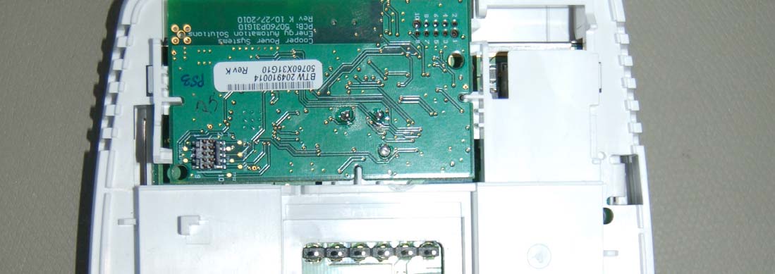
Zigbee communication board for Honeywell UtilityPRO thermostat - FCC ID Y86-50760X31 - Cooper Power Systems
Y86-50760X31

Zigbee communication board for Honeywell UtilityPRO thermostat

Apr 27, 2011

Equipment Class

DTS - Digital Transmission System